


SEMINAR 1. Fundamentals of radiologic PHYSICS.pptx
- 1. Fundamentals of Radiological Physics
- 2. Introduction • Radiology: Medical speciality using imaging (X-rays, CT, MRI) to diagnose and treat diseases. • Importance of fundamentals: • Understanding device functionality (e.g., X-ray tubes, detectors). • Digital logic in modern imaging systems. • For achieving Safe use of radiation
- 3. Electricit y • It is a form of energy resulting from the existence of charged particles (such as electrons or protons), either statically as an accumulation of charge or dynamically as a current . • The flow of charge in a conductor is defined as electricity. There are two branches of electrical physics: • Electrostatics : It is a branch of physics that deal with the study of charge at rest. Electrostatics deal with the study of forces, fields and potential arise from static charge. • Electrodynamic : Electrodynamics is the study of electric charges in motion.
- 4. Electrostatic Charge Definition: Electrostatic charge is a buildup of electric charge that occurs when electrons are transferred from one material to another. Coulomb’s Law: The force between two charges is proportional to their product and inversely proportional to the square of the distance between them. Applications in Radiology: Electrostatic principles are used in image intensifiers and digital detectors to manipulate electron flow.
- 5. ELECTRICAL CURRENT • The flow of electric charge in a conductor is called an electric current. • It is equal to the quantity of charge passing a given point in one second. • Charge may flow through solid, liquid and gas or vacuum. • The unit of current is called ampere (A). The electric current through a wire is called one ampere, if one coulomb of charge flows through the wire in one second. • It is found that one ampere current consists of 6.281 × 10¹⁸ electrons/sec. • In practice, milliampere (mA) and microampere (µA) are used as units, 1 mA = 10–3 A, and 1 µA = 10–6 A. 5
- 6. Types of Electric Current • There are two kind of electrical current- 1. Direct current 2. Alternating current • Direct current- DC current is defined as a uni- directional flow of electric charge. In DC current, the electrons move from an area of negative charge to an area of positive charge without changing direction. This is unlike alternating current (AC) circuits, where current can flow in both directions. • Alternating current- An alternating current (AC) is defined as an electric current that changes direction and magnitude periodically. Unlike direct current (DC), which flows in one direction,
- 7. Types of Alternating Current Single phase A.C- Only one coil rotating between two magnetic poles and giving rise to one sine wave is called single phase alternating current. Polyphase A.C- Three coil rotating between two magnetic poles and giving rise to three sine wave is called polyphase or three phase alternating current. These three coil are displaced equally from each other within 360. 7
- 8. Capacitors • A capacitor is an electrical component that stores and releases electrical energy in the form of an electric field. It consists of two conductive plates separated by an insulating material called a dielectric. When a voltage is applied, one plate accumulates positive charge while the other accumulates negative charge, creating an electric field between them. • Dielectric Material: Increases capacitance. • Applications: • Used in X-ray machine circuits to store and release charge rapidly. • Smoothing circuits in rectifiers.
- 9. •The capacitance (C) of a capacitor is given by: : where: • C = Capacitance (in Farads, F) • ε = Permittivity of the dielectric material • A = Area of the capacitor plates (m²) • d = Distance between the plates (m) •Another important formula is the charge- voltage relationship: Q=CV where: • Q = Charge stored (Coulombs, C) • V = Voltage applied (Volts, V)
- 10. Electrical Energy • Definition: The ability to do work due to electric potential. • Formula: W=VQ (Work = Voltage × Charge). • UNITS :Joule (J) / Kilowatt-hour(kWh) / Electron-Volt(eV) • ELECTRIC Power (P): It is the rate at which work is done or energy is transformed in an electrical circuit. Simply put, it is a measure of how much energy is used in a span of time. • P=VI (Power = Voltage × Current). S.I. UNIT :Watt, joule per second • Applications: • X-ray production relies on converting electrical energy into electromagnetic radiation. • Efficient power management in radiology equipment enhances performance and safety.
- 11. Magnetic Field and Electric Charge Magnetic Field (B): Region around a magnet where magnetic forces act. •Relation to Electricity: Moving electric charges generate a magnetic field. •Right-Hand Rule: Determines the direction of the magnetic field around a current-carrying conductor. •Applications in Radiology: •MRI scanners use strong magnetic fields to align protons in the body. •Magnetic fields influence electron movement in cathode-ray tube.
- 12. Electromagnet ic Induction (EMI) Faraday’s Law: A changing magnetic field induces an electric current in a conductor. Lenz’s Law: The induced current opposes the change that caused it. Mutual Induction: When a changing current in one coil induces voltage in another. Self-Induction: When a changing current in a coil induces voltage within the same coil. Applications in Radiology: Transformers in X-ray machines use mutual induction to step up/down voltage. MRI uses electromagnetic induction to generate signals from tissues
- 13. Electromagnetic Induction (EMI) • Electromagnetic induction is the process of generating an electric current in a conductor by changing the magnetic field around it. This phenomenon is the basis for many electrical devices used in radiology, including X-ray transformers, generators, and MRI systems.
- 14. Faraday’s Law of Electromagnetic Induction Michael Faraday discovered that a changing magnetic field induces an electromotive force (EMF) in a conductor. • Faraday’s First Law : An EMF (Voltage) is induced in a conductor whenever there is a change in the magnetic field surrounding it. • Faraday’s Second Law : The magnitude of the induced EMF is directly proportional to the rate of change of the magnetic flux. • More flux change = Higher induced voltage. • Application in Radiology • X-ray generators use electromagnetic induction to transform voltage for the X-ray tube. • MRI scanners rely on changing magnetic fields to induce signals from hydrogen nuclei.
- 15. Faraday’s Laws of Electromagnetic Induction • First Law: A changing magnetic field in a coil induces an electromotive force (EMF) in it or a nearby coil. • Second Law: The magnitude of induced EMF is proportional to the rate of change of magnetic flux: E = N*d − Φ/dt; where: • E = Induced EMF (volts) • N = Number of turns in the coil • dΦ = Rate of change of magnetic flux • In transformers, AC voltage applied to the primary coil creates a varying magnetic flux in the core, which induces a voltage in the secondary coil.
- 16. Lenz’s Law Lenz’s Law states that the induced EMF opposes the change that caused it. • In a transformer, this means that the induced current in the secondary coil opposes the magnetic flux change in the primary coil. • This opposition ensures efficient energy transfer but also leads to losses like eddy currents and hysteresis losses.
- 17. Mutual Induction Definition: When a changing current in one coil induces a voltage in a nearby coil. • Requires two coils: • Primary Coil: The one connected to the power source. • Secondary Coil: The one where EMF is induced. • Applications in Radiology A. Step-up and step-down transformers in X-ray machines use mutual induction to modify voltage. B. Autotransformers adjust kV settings in radiographic equipment.
- 18. Self-Induction • Definition: When a changing current in a coil induces an EMF in the same coil. Occurs due to the coil’s own changing magnetic field.
- 19. Vacuum Tubes • Vacuum tubes (also called electron tubes or thermionic valves) are electronic devices that control the flow of electrons in a vacuum. I. Vacuum Diodes II. Triodes III. Tetrodes and Pentodes
- 20. Gas-Filled Thermionic Tubes •Structure: Contains a small amount of gas (e.g., Argon, Mercury). •Working: •The presence of gas increases conduction efficiency and reduces power loss. •Used where higher current handling is needed. •Application: •Thyratrons (gas-filled tubes) were used in early X-ray generators for high-voltage switching. •Some fluoroscopy circuits used them before semiconductor advancements.
- 21. •Cold-cathode gas-filled diode, also known as glow tube, is shown schematically in Fig. (a). The dot within the circle indicates the presence of gas in the tube envelope. Most of the cold-cathode gas-filled tubes are used as diodes. • Cold-cathode gas-filled triode, also known as grid glow tube
- 22. Semiconductor Devices Semiconductors replaced vacuum tubes due to their compact size, efficiency, and reliability. • Junction Diodes • Barrier-Layer Rectifiers • Transistors
- 23. Junction Diodes • Structure: A PN-junction (combination of p- type and n-type semiconductors). • Working: • Allows current only in one direction (forward bias). • Blocks current in reverse bias (acts as a rectifier). • Application: • Used in rectifiers of modern X-ray machines to convert AC to DC. • Found in power supply units of imaging systems.
- 24. Construction of Diode • There are two types of semiconductor material; • Intrinsic and Extrinsic semiconductor. • An intrinsic semiconductor is a pure semiconductor in which hole and electrons are available in equal numbers at room temperature. • In an extrinsic semiconductor, impurities are added to increase the number of holes or the number of electrons. • Impurities are tri-valent (boron, indium, aluminum) or • Pentavalent (phosphorous, Arsenic, Antimony).
- 25. • A semiconductor diode has two layers. One layer is made of a P-type semiconductor present, and the second layer is made of an N-type semiconductor layer. • If we add trivalent impurities in silicon or germanium, a greater number of holes are present, and it is a positive charge. Hence, this layer is known as the P-type layer. • If we add pentavalent impurities in silicon or germanium, a greater number of electrons are present, and it is a negative change. Hence, this layer is known as the N-type layer. • The diode is formed by joining both N-type and P-type semiconductors together. This device is a combination of P-type and N-type semiconductor material hence it is also known as PN Junction Diode.
- 26. • A junction is formed between the P-type and N-type layers. This junction is known as PN junction. • A diode has two terminals; one terminal is taken from the P-type material, and it is known as Anode. The second terminal is taken from the N-type material, and it is known as Cathode.
- 27. Barrier-Layer Rectifiers • Definition: Special diodes that efficiently rectify current using a metal-semiconductor junction. • Application: • High-frequency rectification in X-ray power supplies. • Used in detectors for signal processing in imaging equipment.
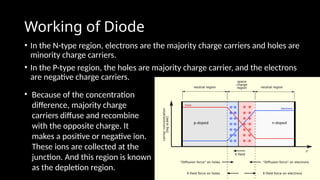
- 28. Working of Diode • In the N-type region, electrons are the majority charge carriers and holes are minority charge carriers. • In the P-type region, the holes are majority charge carrier, and the electrons are negative charge carriers. • Because of the concentration difference, majority charge carriers diffuse and recombine with the opposite charge. It makes a positive or negative ion. These ions are collected at the junction. And this region is known as the depletion region.
- 29. • When anode terminal (p-type) of diode is connected to a negative terminal and cathode(n-type) is connected to the positive terminal of a battery, the diode is said to be connected in reverse bias. • Similarly, when anode terminal (p- type) is connected with a positive terminal and cathode (n-type) is connected with the negative terminal of the battery, the diode is said to be connected in forward bias.
- 31. Transistors • Types: • Bipolar Junction Transistors (BJT) – Uses electron and hole movement for amplification. • Field-Effect Transistors (FET) – Voltage-controlled, used in switching applications. • Function: Used as amplifiers, switches, and oscillators in electronic circuits. • Application: • Used in digital control circuits of X-ray machines. • Found in MRI and CT scanners for signal amplification.
- 32. Photoelectric Devices • These devices convert light energy into electrical signals, essential in radiology detectors.
- 33. Vacuum Phototubes • Structure: Similar to a diode but with a light- sensitive cathode. • Working: When light falls on the photo-emissive surface, electrons are released, initiating the photoelectric effect. Electrons emitted from the cathode move toward the positively charged anode, generating an electric current. • Application: Used in older X-ray film readers for automatic exposure control.
- 34. Photomultipliers (PMT) • Working: • Light photons strike the photocathode, releasing electrons. • Electrons are amplified through a series of dynodes. • Application: Used in scintillation detectors for IITV, CT and PET imaging. •Structure: A vacuum tube with multiple electrodes (dynodes).
- 35. Semiconductor Photoelectric Devices • Types: • Photodiodes: Convert light into electrical current.(solar cells) • Phototransistors: Amplify the light signal.(similar to photodiodes with amplification capability) • CCD (Charge-Coupled Devices): Used in digital imaging sensors. • Application in Radiology: • Photodiodes are used in digital X-ray detectors. • CCDs are used in modern digital imaging systems.
- 36. Amplifiers •Definition: Devices that increase the strength of electrical signals. •Types: 1.Operational Amplifiers (Op-Amps) – Used in signal processing. 2.Power Amplifiers – Used in high-voltage control. •Application: •Used in MRI and CT systems to amplify weak signals. •Helps in boosting detector signals in fluoroscopy and digital radiography.
- 37. Oscillators • Definition: Circuits that generate continuous AC waveforms. It converts DC power into an AC signal of a specific frequency • Types: • Positive Feedback Oscillators – Sustain oscillations. • Negative Feedback Oscillators – Used for signal stability. • Application: • Used in timing circuits of medical imaging devices. • Found in radiofrequency (RF) systems of MRI.
- 38. TRANSFORMER DEFINITION – A transformer is a device that either increases or decreases the voltage and current in a circuit. • The transformer assembly is a grounded metal box filled with oil. • It contains a low-voltage transformer for the filament circuit and a high voltage transformer and a group of rectifiers for the high voltage circuit. 38
- 39. THE NEED OF TRANSFORMER FOR X- RAY TUBE The x-ray generator receives 220 V, 50 Hz Alternating current. Filament heating requires a potential difference of approximately 10 V, whereas electron acceleration requires a potential difference that can be varied between 40,000 and 150,000 V. Transformers are used to change the potential difference of the incoming electric energy to the appropriate level. 39
- 40. PRINCIPLE Transformer is based on the principle of Electromagnetic Induction i.e., when current flows through the primary coil, it creates a magnetic field within the core and this magnetic field induces a current in the secondary coil. 40
- 41. CONSTRUCTION OF TRANSFORMER CONSTRUCTION:- A transformer consists of two wire coils wrapped around a closed core. The core may be simple rectangle with the winding wound around opposite sides of the rectangle. It contains two circuits : 1. PRIMARY CIRCUIT: The circuit containing the first coil which is connected to the available electric energy source. 2. SECONDARY CIRCUIT: The circuit containing the second coil from which comes the modified electric energy. 41
- 42. WORKING OF A TRANSFORMER • STEP 1 – Primary coil of the transformer is supplied with Alternating Current. • STEP 2 – As the current flows through the primary coil, a changing magnetic field is set up around it in the iron core. • STEP 3 – As per the principle of Electromagnetic Induction, current is induced in the secondary coil. 42
- 43. The working of transformers is governed by the following laws: • Faraday’s Laws of Electromagnetic Induction • Lenz’s Law • Transformer Turns Ratio Law • Power Conservation Law (Ideal Transformer)
- 44. Transformer Turns Ratio Law • The voltage ratio between the primary and secondary coils is given by: Vs/Vp=Ns/Np ; where; • Vp= Primary voltage • Vs= Secondary voltage • Np= Number of turns in the primary winding • Ns= Number of turns in the secondary winding 44 Types Based on Turns Ratio: •Step-Up Transformer: Ns>Np , so Vs>Vp (increases voltage). •Step-Down Transformer: Ns<Np , so Vs<Vp(decreases voltage).
- 45. Power Conservation Law (Ideal Transformer) An ideal transformer has no losses, so power input equals power output: 𝑃𝑝=𝑃𝑠 OR 𝑉𝑝𝐼𝑝=𝑉𝑠𝐼𝑠 ;where: 𝑃𝑝 = Power in primary coil 𝑃𝑠 = Power in secondary coil 𝐼𝑝 = Primary current 𝐼𝑠 = Secondary current This means that if voltage is increased, current decreases, and vice versa.
- 46. • For example, the voltage across the primary coil was 100 V, and that across the secondary coil 30,000 V. If the current in the primary coil is 30 A, then the current in the secondary coil will be : 100 x 30 = 30,000 x Is Is = 0.1 A (100 mA) • In a step-up transformer, the current on the secondary side (Is) is smaller than the current on the primary side (Ip). • In a step-down transformer, the secondary current is larger than the primary current 46
- 47. TRANSFORMER RATING • Transformer rating is the statement described by the manufacturers in regard to the limits of useful output given by the transformer. • It is important to know the rating and maximum limit under which we can operate a transformer because if it is operated beyond that limit, it may become too hot leading to damage. 47
- 48. TYPES OF TRANSFORMER • There are two basic circuits in a diagnostic x-ray unit. • One circuit contains the step- up transformer and supplies the high voltage to the x-ray tube. • The other circuit contains a step-down transformer and supplies the power that heats the filament of the x-ray tube. • A transformer called the ‘Auto- transformer’ supplies the primary voltage for both these circuits. 48
- 49. 1. STEP-UP TRANSFORMER • A transformer with more turns in the secondary coils than in the primary coil increases the voltage of the secondary circuit and is called a Step-up transformer. • Step-up transformer increases the voltage and decreases the current. • Step-up transformer is connected between main supply and x-ray tube. • When electrons are produced, they need to be accelerated from cathode to anode for x-ray production. • A very high voltage in the range of 150 kVp is required which is provided by high voltage transformer. 49
- 50. •Purpose:- •1.To provide very high voltage(of the order of 40kV - 150 kV) to produce x– rays. •2. Primary connection from autotransformer •3. Secondary connection to rectifier circuit. •4. Provide attachment for mA meter. 50
- 51. 2. STEP-DOWN TRANSFORMER • A transformer with fewer turns in the secondary coil than in the primary coil decreases the voltage and is called a Step-down transformer. • It decreases the voltage and increases the current. • Step-down transformer is connected directly to the filament of the tube. 51
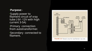
- 52. •Purpose:- •Supply power to filament circuit of xray tube ( 6V -12V with high current 3-5A) •Primary connection from autotransformer. •Secondary connected to filament. 52
- 53. 3. AUTO-TRANSFORMER • An auto-transformer is designed to supply the voltage of varying magnitude to several different circuits of the x-ray machine including both the filament circuit and high voltage circuit. • An auto-transformer consists of a single winding wound on a laminated closed core. 53
- 54. AUTO-TRANSFORMER cont. • Provides voltage for the x-ray tube filament circuit • Provides voltage for the primary of the high voltage transformer • Provides suitable voltage for subsidiary circuits • Provides a convenient location for the kVp meter that indicates the voltage to be applied across the x-ray tube. • The autotransformer works on the principle of SELF INDUCTION. • An Alternating current applied between the input points will induce a flow of magnetic flux around the core. • This magnetic flux will link with all the turns forming the coil, inducing a voltage into each turn of the winding. 54
- 55. EFFICIENCY OF TRANSFORMER It is the ratio of output power and input power in watts, expressed as percentage(%). EFFICIENCY= (OUTPUT POWER × 100) / INPUT POWER • Ideally it should be 1 i.e., output = Input, but actually it is less than 1 i.e., output < input. • So, efficiency of transformer is never 100% and this is due to the losses of transformer. 55
- 56. TRANSFORMER LOSSES • Copper loss due to resistance in the coils:- • when current flows through the wires, the material of wires resist the current. • Greater the current, greater is the resistance. So, some power is lost in overcoming resistance which is called copper loss. • Copper losses are highest at full load. • SOLUTION:- • Material as low resistance as possible is selected eg., pure 56
- 57. IRON LOSSES (Losses in core windings) 1. HYSTERESIS LOSS:- • Hysteresis loss is a heat loss caused by the magnetic properties of the core. • The continuous movement of the magnetic particles, as they try to align themselves with the magnetic field, produces molecular friction. • This, in turn, produces heat. This heat is transmitted to the windings. The heat causes windings resistances to increase. Minimized by: Using special alloys(SILICON STEEL) for the coil. 2. EDDY CURRENT LOSS:- • Eddy currents are also set up due to changing magnetic field and loss appears as heat in the core. Minimized by: Laminating the core. 57
- 58. LOCATION OF TRANSFORMERS IN CIRCUIT 58
- 59. • Mechanical auto-transformers are NOT PRESENT NOWADAYS AS IT IS REPLACED WITH NEWER TECHNOLOGIES such as solid state or electronic autotransformers
- 60. RECTIFICATION An x-ray tube to produce x-rays requires that its filament should satisfy two conditions:- 1. That it should be heated so that the electrons are given off. 2. That it should be connected to a voltage source which makes it negative in respect to anode so that electrons are attracted towards anode. • Current flows through the x-ray tube only in one direction i.e. from cathode to anode while the voltage from the transformer is alternating current. • This conversion from alternating current to direct current (unidirectional) is called RECTIFICATION. 60
- 61. RECTIFIER • A rectifier is a device that allows an electrical current to flow in one direction but doesn’t allow current to flow in other direction. • Rectifiers are incorporated in the x-ray circuit in series with x-ray tube. • Exactly the same current flows through the x-ray tube and the rectifier. • High voltage rectifiers can be of vacuum tube type or solid state composition. • X-ray tube is a sort of valve type rectifier or diode rectifier as it has two electrodes and allows the current to flow in one direction only. 61
- 62. TYPES OF RECTIFIER 62 THERMIONI C DIODE VALVES SOLID STATE DEVICES
- 63. THERMIONIC DIODE VALVES • An evacuated tube with two electrodes in it is called THERMIONIC DIODE VALVE. Hence it is like an x-ray tube having:- • A glass envelope enclosing a vacuum. • Two electrodes within the glass envelope, one of which is a heated filament. • The filament of a valve is heated by a step-down transformer and emits electrons which are drawn across to the anode. • When a potential difference is applied across both the electrodes and the 63
- 64. FUNCTIONING OF A DIODE VALVE:- •If the valve is connected in a complete circuit such that cathode is -ve with respect to anode electrons are drawn towards the anode and valve passes current. • If the cathode is +ve with respect to the anode, no electrons will be drawn across the valve and it blocks the current thus the supply of current to x- ray tube is unidirectional only. But these diode valves which were used earlier are replaced with solid state rectifiers. • Hence, its function is to pass current in one direction only and to block any reverse flow. 64
- 65. SOLID STATE RECTIFIER 65 • As the name solid state implies, conduction takes place by electron travel through solid materials. • The material used are semiconductors. Their characteristics come in between metals and non- metals. • Si(silicon) and Ge (germanium) are semiconductors generally used in these. • SELENIUM was the first material used for solid state rectifiers. • Today, most X-ray generators use silicon rectifiers which are 20-30cm in length and 2cm in diameter.
- 66. The Self Rectified HT Circuit •It is also known as single phase alternator, in which as alternating current electrical generator that produces a single, continuously alternating voltage. 66
- 67. • In self rectified HT circuit:- The X-ray tube acts itself as a rectifier. It is directly connected to secondary windings of transformer. • Cathode connected to secondary windings and anode to other. • Current only flows from cathode to anode. • Cathode is source of free electrons. 67
- 68. APPLICATIONS • PORTABLE AND LOW POWER MOBILE AND DENTAL UNIT. ADVANTAGES:- DISADVANTAGE • Small in size Hot anode can emit electrons • Simple design • Simple to operate • Light in weight • Less cost 68
- 69. Voltage applied to tube When the two rectifiers are connected in series with the x-ray tube and cathode is negative terminal and anode is positive terminal, the electrons will flow from cathode to anode. • When the voltage reverses during inverse half of the alternating cycle, the rectifiers stops current flow. • When rectifiers are used in this manner they produce half wave rectification. • The only advantage of rectifiers is that they protect the x-ray tube from full potential of inverse cycle. Half wave rectified circuit (Single Pulse)
- 70. - - R1 R2 R1 R2 70 Half wave rectified circuit First Half Cycle: Diodes closed Voltage applied to tube Tube current (mA) results Second Half Cycle: Diodes open No voltage applied to tube No tube current (mA)
- 71. LIMITATIONS • 60 pulses per second • Only positive half cycle of HT transformer used • Inefficient • Negative half cycle wasted 71 Blocked (not used) Applied to x-ray tube Output of High Tension Transformer Applied to X-ray Tube
- 72. Single phase full wave rectified circuits (Two Pulse) • In this circuit both half cycles of AC are used to produce X-rays by employing a bridge of four rectifiers. • Both halves of alternating voltage are used to produced X- rays so the x-ray output per unit time is twice as large as it is with half wave rectification. 72
- 73. First Half Cycle Second Half Cycle Voltage applied to tube (also mA waveform) R1 R2 R3 R4 R1 R2 R3 R4
- 74. 74 • Higher output than self or half wave rectified circuits. • Less strain on HT cables and less insulation cost. Tube Output of High Tension Transformer Applied to X-ray Tube
- 75. LIMITATIONS • COSTLY • MORE COMPLEX • HEAVIER, NOT EASY TO TRANSPORT • LARGE IN SIZE • RIPPLE FACTOR IS 100% AS IT IS PULSATING X-RAY BEAM WITH VOLTAGE VARIATION BETWEEN ZERO TO PEAK AND AGAIN ZERO 75
- 76. SEMICONDUCTORS • The heart of solid state rectifier is a semiconductor. • Semiconductors are material whose electrical properties lie between CONDUCTORS and INSULATOR. • Silicon and Germanium are the examples of semiconductors. • Pure semiconductor have little conduction towards electricity, so to enhance the conductivity impurities are added by a process called doping. According to addition of impurities it can be classified into two types:- P-type semiconductor N-type semiconductor 76
- 77. P-TYPES CONDUCTOR • It is an extrinsic semiconductor which is obtained by doping trivalent impurity atoms such as boron, gallium, indium to the pure germination or silicon semiconductor. • The impurity atoms added create vacancies of electrons(holes)in structure and are called “acceptor” atoms. • The holes are majority charge carries and electrons are minority carriers. 77
- 78. N-TYPE SEMICONDUCTOR • Materials with surplus free electrons can be produced by putting minute amounts of penta-valent impurities into semiconductors and these free electrons are able to move through the substance. • Such materials with many free electrons are called N-type materials. • Examples are:- silicon and germanium with a minute amount of phosphorous added impurity. • Impurity atoms added provide extra electrons in the structure and are called “donor” atoms. 78
- 79. P-N JUNCTION •It is formed by joining P-type and N-type semiconductors together called PN junction. •Thus, electron easily flow from the N-type layer(electron rich) towards P-type layer(hole rich) i.e. from “donor” towards “acceptor” but not in opposite direction from P towards N type. Hence unidirectional flow of current is obtained. •The block to the current in reverse direction occurs at the junctions between the two materials N type and P type i.e. the region where the barrier exists is very thin. 79
- 80. •Connection of diode to potential source is called BIASING. •When higher potential of sources is connected to P-side of diode then it is FORWARD BIASED. •When higher potential of sources is connected to N-side of diode then it is REVERSE BIASED. 80
- 81. ADVANTAGES OF SOLID STATE OVER DIODE VALVE RECTIFIER • Longer life • No filament heated • More Robust • Smaller in size • More compact that is occupy less space, better for mobile unit. • More reliable 81
- 82. • The core of a transformer is laminated. It is made up of thin sheets of special iron alloys separated from each other by thin insulating layers. • These sheets are clamped tightly together. The purpose of the laminations is to reduce eddy currents, which waste power and appear as heat in the transformer core. • Current only flows through the secondary coil when magnetic field changes(either increases or decreases) • No current flows during steady state of magnetic field. 82
- 83. EXPOSURE TIMERS There are many ways to control the length of x-ray exposure. The following are the types of the exposure timer:- 1) Mechanical timer (rarely used today) 2) Electronic timer 3) Automatic exposure control (photo-timer) 4) Ionization chamber autotimer 83
- 84. ELECTRONIC TIMER • Principle:-It works on the principle that the length of exposure is determine by the time required to charge a capacitor through a selected resistance. • When exposure button starts, it also starts charging the capacitor. The exposure is terminated when the capacitor is charged to a value necessary to turn on associate electronic circuit. • Time can be varied by varying the value of the resistance in charging the circuit. 84
- 85. AUTOMATIC EXPOSURE CONTROL (PHOTOTIMER) • Mechanical and electronic timer are subjected to human error. To overcome the human error the automatic phototimer is used to control the x-ray exposure. • It can detect radiation which passing through different density of tissue of human body and produce a small electric current which is used to charge the capacitor. • When the capacitor reaches the predetermined charge, it can used to bias the gate of SCR in the x-ray circuit and cause the exposure to terminate. 85
- 86. IONIZATION CHAMBER AUTOTIMER • An ionisation chamber consists of two thin parallel sheet of aluminium or lead foil. The gas usually room air present between the plates. • The gas become ionised when struck by the radiation and ionisation is directly proportional to the amount of radiation. • The capacitor starts charging, when gas ionised by radiation. • The electric circuit is activated and will terminate the exposure. 86
- 87. Conclusion • ELECTRICAL & Electronic components form the backbone of modern radiographic imaging systems. Basic knowledge of these electronic component (vacuum diodes, semiconductor diodes, generators, rectifiers, semiconductors, photodiodes, charge- coupled devices (CCDs)), and other semiconductor devices are crucial for comprehending how radiological equipments function efficiently and accurately. • The evolution from vacuum tubes to semiconductor devices has revolutionized medical imaging, leading to more compact, energy-efficient, and high-performance diagnostic tools. Rectifiers and generators play a vital role in supplying and regulating power, while photodiodes, CCDs with advanced FPD’s enhance image acquisition and processing. These advancements have significantly improved image quality, patient safety, and diagnostic precision. • Knowledge of fundamental concepts is also important in maintaining dose to patient , their attendants and staff to minimum levels . • By integrating fundamental physics with cutting-edge technology, radiology continues to progress, enabling faster and more accurate diagnoses. A solid grasp of these fundamental concepts empowers radiologic technologists and medical professionals to operate imaging systems effectively, troubleshoot technical issues, and contribute to further innovations in the field.