SlideShare a Scribd company logo
INTERNATIONAL SCHOOL OF TECHNOLOGY &
SCIENCES (FOR WOMEN)
DEPARTMENT OF ELECTRONICS &
COMMUNICATION ENGINEERING
Prepared By:
Mr. K V VENKATARAMANA,
Assistant Professor.
K V VENKATARAMANA‖ ECA ‖ Dept of ECE ‖ ISTS
II BTECH II SEMESTER
ELECTRONIC CIRCUIT ANALYSIS
UNIT VI
Contents:
Introduction to Tuned Amplifier
Q-Factor
Small signal tuned amplifier
Capacitance single tuned amplifier
Double Tuned Amplifier
Effect of Cascading single Tuned Amplifier
Staggered tuned Amplifiers
Stability of Tuned Amplifiers
K V VENKATARAMANA‖ ECA ‖ Dept of ECE ‖ ISTS
DEFINITION:-
An amplifier circuit in which the load circuit is a
tank circuit such that it can be tuned to pass or amplify
selection of a desired frequency or a narrow band of
frequencies, is known as Tuned Circuit Amplifier.
K V VENKATARAMANA‖ ECA ‖ Dept of ECE ‖ ISTS
CHARACTERISTICSOFTUNEDAMPLIFIER
Tuned amplifier selects and amplifies a single frequency
from a mixture of frequencies in any frequency range.
A Tuned amplifier employs a tuned circuit.
It uses the phenomena of resonance, the tank circuit which
is capable of selecting a particular or relative narrow band
of frequencies.
The centre of this frequency band is the resonant frequency
of the tuned circuit .
Both types consist of an inductance L and capacitance C
with two element connected in series and parallel.
K V VENKATARAMANA‖ ECA ‖ Dept of ECE ‖ ISTS
RESONANCECIRCUITS:
•When at particular frequency the inductive reactance
became equal to capacitive reactance and the circuit then
behaves as purely resistive circuit. This phenomenon is
called the resonance and the corresponding frequency is
called the resonant frequency.
C
L
Tu ned c ircuit
K V VENKATARAMANA‖ ECA ‖ Dept of ECE ‖ ISTS
Resonance
circuits
ParallelSeries
K V VENKATARAMANA‖ ECA ‖ Dept of ECE ‖ ISTS
Classification of
Tuned Circuits
Small signal
amplifier, low
power, radio
frequency
Class A
Single Tuned
circuit(one
parallel circuit
is employed)
Double tuned
circuit(two
tuned circuit
are employed)
Staggered
Tuned amplifier
Large signal
amplifier, low
power, radio
frequency
Class B&C
Shunt peaked
tuned with
higher band
width
K V VENKATARAMANA‖ ECA ‖ Dept of ECE ‖ ISTS
CLASSIFICATION OF TUNED AMPLIFIER
Tuned
amplifier
Small Signal
Amplifier
Single
Tuned
Amplifier
Double
Tuned
Amplifier
Stagger
Tuned
Amplifier
Large signal
Amplifier
K V VENKATARAMANA‖ ECA ‖ Dept of ECE ‖ ISTS
CLASSIFICATIONOFTUNED
AMPLIFIERS
Small Signal Tuned Amplifiers :- They are used to amplify
the RF signals of small magnitude.
They are further classified as:
(a)Single Tuned Amplifiers:- In this we use one
parallel tuned circuit in each stage.
(b)Double Tuned Amplifiers:- In this we use two
mutually coupled tuned circuits for every stage both of
tuned circuits are tuned at same freq.
(c)Stagger Tuned Amplifiers:- It is a multistage amplifier
which has one parallel tuned circuit for every stage but
tuned frequency for all stages
K V VENKATARAMANA‖ ECA ‖ Dept of ECE ‖ ISTS
(2) Large signal tuned amplifiers:-
They are meant for amplifying large signals in which
large RF power is involved & distortion level is also
higher. But tuned circuit itself eliminates most of the
harmonic distortion.
K V VENKATARAMANA‖ ECA ‖ Dept of ECE ‖ ISTS
SERIESRESONANT CIRCUIT
•It is the circuit in which all the resistive and
reactive components are in series.
K V VENKATARAMANA‖ ECA ‖ Dept of ECE ‖ ISTS
SERIESRESONANT LC
K V VENKATARAMANA‖ ECA ‖ Dept of ECE ‖ ISTS
SERIESRESONANTCIRCUIT:
Impedance Of The Circuit: - Z = { R2 + (XL – Xc)2}1/2
Z = { R2 + (ωL – 1/ ωC)2}1/2
For resonant frequency:-
(XL = XC )
XL = ωL =
XC = 1/ ωC =
2 π frL
1 / 2 π frC
K V VENKATARAMANA‖ ECA ‖ Dept of ECE ‖ ISTS
SERIESRESONANTCIRCUIT
Since at resonance,
XL = Xc
2 π frL = 1 / 2ПfrC
fr = 1 / 2 π √LC ωr
fr = 1 / √LC
K V VENKATARAMANA‖ ECA ‖ Dept of ECE ‖ ISTS
RESONANCECURVEOFSERIES
RESONANTCIRCUIT:
K V VENKATARAMANA‖ ECA ‖ Dept of ECE ‖ ISTS
QUALITYFACTOR:
• It is voltage magnification that circuit produces at
resonance is called the Q factor.
Imax XL
/ Imin R• Voltage Magnification =
= XL/ R
• At Resonance =
XL/R = XC/R
ωrL / R = 1 /
ωrRC
K V VENKATARAMANA‖ ECA ‖ Dept of ECE ‖ ISTS
THUS
Qr = ωrL / R = 1/ ωrC R
= 2 π fr L / R
= (2 π L / R) * (1 / 2 π √LC )
= √(L/C) / R
=
{ tan Ф = power factor of coil }
tanФ
K V VENKATARAMANA‖ ECA ‖ Dept of ECE ‖ ISTS
IMPORTANTPOINTS
(1) Net reactance , X = 0.
(2) Impedance Z = R .
(3) Power factor is unity.
(4) Power expended = 6 watt.
•
•
Current is so large & will produce large voltage
across inductance & capacitance will be equal in
magnitude but opposite in phase.
Series resonance is called an acceptor circuit
because such a circuit accepts current at one
particular frequency but rejects current at other
frequencies these circuit are used in Radio –
receivers .
K V VENKATARAMANA‖ ECA ‖ Dept of ECE ‖ ISTS
REACTANCECURVESERIESRESONANT
CIRCUIT
XL = 2ΠfL
X = XL - XC
XC = 1
2ΠfC
R
fr
K V VENKATARAMANA‖ ECA ‖ Dept of ECE ‖ ISTS
PARALLELORCURRENTRESONANCE
K V VENKATA RAMANA‖ ECA ‖ Dept of ECE ‖ ISTS
PARALLELORCURRENTRESONANCE
•When an inductive reactance and a capacitance are connected in
parallel condition may reach under which current resonance (also
known as parallel or anti- resonance ) will take palace.
•The frequency at which this happened is known as resonant
frequency. Current will be in resonance I reactive component of R -
L branch.
•IR-L sinФ R-L = Reactive component of capacitive branch,
neglecting leakage reactance of capacitor C.
K V VENKATA RAMANA‖ ECA ‖ Dept of ECE ‖ ISTS
FREQUENCY V/S IMPEDANCE CURVE FOR
LCR CIRCUIT
K V VENKATA RAMANA‖ ECA ‖ Dept of ECE ‖ ISTS
Inductance Quality factor (Q)
24
K V VENKATA RAMANA‖ ECA ‖ Dept of ECE ‖ ISTS
RESONANTRESONANCE CURVE OF PARALLEL
CIRCUIT :
With low resistance
With high resistance
current
fR
K V VENKATA RAMANA‖ ECA ‖ Dept of ECE ‖ ISTS
25
26 K V VENKATA RAMANA‖ ECA ‖ Dept of ECE ‖ ISTS
27
92
29
K V VENKATA RAMANA‖ ECA ‖ Dept of ECE ‖ ISTS
C o n d u c tan ce(R )
30
Q
t
eff
 Susp tan ce(L / C )
SINGLETUNEDAMPLIFIER USINGFET
K V VENKATA RAMANA‖ ECA ‖ Dept of ECE ‖ ISTS
LIMITATION:
• This tuned amplifier are required to be highly selective.
But high selectivity required a tuned circuit with a high Q-
factor .
• A high Q- factor circuit will give a high Av but at the
same time , it will give much reduced band with because
bandwidth is inversely proportional to the Q- factor .
• It means that tuned amplifier with reduce bandwidth may
not be able to amplify equally the complete band of
signals & result is poor reproduction . This is called
potential instability in tuned amplifier.
K V VENKATA RAMANA‖ ECA ‖ Dept of ECE ‖ ISTS
Double tuned Amplifier:
K V VENKATA RAMANA‖ ECA ‖ Dept of ECE ‖ ISTS
34
K V VENKATA RAMANA‖ ECA ‖ Dept of ECE ‖ ISTS
35
36
K V VENKATA RAMANA‖ ECA ‖ Dept of ECE ‖ ISTS
37
K V VENKATA RAMANA‖ ECA ‖ Dept of ECE ‖ ISTS
38
K V VENKATA RAMANA‖ ECA ‖ Dept of ECE ‖ ISTS
39
40
41
K V VENKATA RAMANA‖ ECA ‖ Dept of ECE ‖ ISTS
STAGGERTUNEDAMPLIFIERS:
K V VENKATA RAMANA‖ ECA ‖ Dept of ECE ‖ ISTS
43
44
K V VENKATA RAMANA‖ ECA ‖ Dept of ECE ‖ ISTS
Stability Considerations
45
Tuned amplifiers
Tuned amplifiers
Tuned amplifiers
K V VENKATA RAMANA‖ ECA ‖ Dept of ECE ‖ ISTS
Video Amplifiers (IC MC1550)
K V VENKATA RAMANA‖ ECA ‖ Dept of ECE ‖ ISTS
APPLICATIONS OF TUNED AMPLIFIER
Tuned amplifiers serve the best for two purposes:
a) Selection of desired frequency.
b) Amplifying the signal to a desired level.
USED IN:
Communication transmitters and receivers.
In filter design :--Band Pass, low pass, High pass and
band reject filter design.
K V VENKATA RAMANA‖ ECA ‖ Dept of ECE ‖ ISTS
ADVANTAGES
It provides high selectivity.
It has small collector voltage.
Power loss is also less.
Signal to noise ratio of O/P is good.
They are well suited for radio transmitters and
receivers .
K V VENKATA RAMANA‖ ECA ‖ Dept of ECE ‖ ISTS
DISADVANTAGES
They are not suitable to amplify audio
frequencies.
If the band of frequency is increase then design
becomes complex.
Since they use inductors and capacitors as tuning
elements, the circuit is bulky and costly.
K V VENKATA RAMANA‖ ECA ‖ Dept of ECE ‖ ISTS
Thank you
K V VENKATA RAMANA‖ ECA ‖ Dept of ECE ‖ ISTS

More Related Content

What's hot (20)

PDF
Class a power amplifiers
Adarsh Raj
 
PPTX
Power amplifiers
Sarah Krystelle
 
PPTX
Current mirror
Hossam Moghrabi
 
PPT
DAC-digital to analog converter
Shazid Reaj
 
PPT
Chapter-4 FET (1).ppt
JeelBhanderi4
 
PPTX
Phase Locked Loop (PLL)
Debayon Saha
 
PDF
EC6202 ELECTRONIC DEVICES AND CIRCUITS NOTES
RMK ENGINEERING COLLEGE, CHENNAI
 
PPT
Schmitt trigger circuit
taranjeet10
 
PPTX
Pass Transistor Logic
Sudhanshu Janwadkar
 
PPTX
Pll ppt
parassini
 
PPT
L07 dc and ac load line
Sarah Krystelle
 
PDF
Design of FIR filters
op205
 
PPTX
Transient analysis
Mohammed Waris Senan
 
PPT
transmission-lines
ATTO RATHORE
 
PPT
current mirrors
Mallavarapu Mounika
 
PPTX
Chebyshev filter
MOHAMMAD AKRAM
 
PPTX
Op amp application as Oscillator
veeravanithaD
 
PPTX
Tuned amplifiers
herald Rufus
 
PPTX
3673 mosfet
vidhya DS
 
Class a power amplifiers
Adarsh Raj
 
Power amplifiers
Sarah Krystelle
 
Current mirror
Hossam Moghrabi
 
DAC-digital to analog converter
Shazid Reaj
 
Chapter-4 FET (1).ppt
JeelBhanderi4
 
Phase Locked Loop (PLL)
Debayon Saha
 
EC6202 ELECTRONIC DEVICES AND CIRCUITS NOTES
RMK ENGINEERING COLLEGE, CHENNAI
 
Schmitt trigger circuit
taranjeet10
 
Pass Transistor Logic
Sudhanshu Janwadkar
 
Pll ppt
parassini
 
L07 dc and ac load line
Sarah Krystelle
 
Design of FIR filters
op205
 
Transient analysis
Mohammed Waris Senan
 
transmission-lines
ATTO RATHORE
 
current mirrors
Mallavarapu Mounika
 
Chebyshev filter
MOHAMMAD AKRAM
 
Op amp application as Oscillator
veeravanithaD
 
Tuned amplifiers
herald Rufus
 
3673 mosfet
vidhya DS
 

Similar to Tuned amplifiers (20)

PPT
Eca unit 6
Pavan Mukku
 
PDF
BJT Tuned amplifiers
CvSudhakar
 
PPTX
Tuned Amplifiers in Electronic Circuit Analysis
vaseemahmed33
 
PPT
EC2-NOTES-PPT.ppt
Mythilic4
 
PDF
A Class-C Power Amplifiers Type of Tuned Amplifiers
ShahbazQamar2
 
PPTX
TUNED AMPLIFIERS Simple presentation of Btech students
saivaibhavanuraj
 
DOCX
ELECTRONICS DEVICES AND CIRCUITS
Innovative Electronics Ideas
 
PPT
Ch2.ppt
Ong Gia
 
PPTX
Frequency Response of Amplifier Analog Electronics Engineering
JanviPanwar6
 
DOCX
Transisitor amplifier
HarshitParkar6677
 
PDF
1st year basic electronics
saifam
 
PPTX
Tuned amplifire
Abdulla Al jubayr
 
PPT
Schuler Electronics Instructor CH07 amplifiers part 2.ppt
SreejaSujith2
 
PDF
Review paper
Avani Patel
 
PPTX
ECA_Combined_Presentation_Units1to5.pptx
Urja Shah
 
PPT
ECA PPT.ppt
2305c40034
 
DOCX
Exam 387017RR - Resonant CircuitsWhen you have completed .docx
SANSKAR20
 
PPTX
Radio frequency circuit
pinky0687
 
PPTX
the RESONANCE IN AC CIRCUITS Quality Factor
Dsriniva
 
Eca unit 6
Pavan Mukku
 
BJT Tuned amplifiers
CvSudhakar
 
Tuned Amplifiers in Electronic Circuit Analysis
vaseemahmed33
 
EC2-NOTES-PPT.ppt
Mythilic4
 
A Class-C Power Amplifiers Type of Tuned Amplifiers
ShahbazQamar2
 
TUNED AMPLIFIERS Simple presentation of Btech students
saivaibhavanuraj
 
ELECTRONICS DEVICES AND CIRCUITS
Innovative Electronics Ideas
 
Ch2.ppt
Ong Gia
 
Frequency Response of Amplifier Analog Electronics Engineering
JanviPanwar6
 
Transisitor amplifier
HarshitParkar6677
 
1st year basic electronics
saifam
 
Tuned amplifire
Abdulla Al jubayr
 
Schuler Electronics Instructor CH07 amplifiers part 2.ppt
SreejaSujith2
 
Review paper
Avani Patel
 
ECA_Combined_Presentation_Units1to5.pptx
Urja Shah
 
ECA PPT.ppt
2305c40034
 
Exam 387017RR - Resonant CircuitsWhen you have completed .docx
SANSKAR20
 
Radio frequency circuit
pinky0687
 
the RESONANCE IN AC CIRCUITS Quality Factor
Dsriniva
 
Ad

Recently uploaded (20)

PDF
4 Tier Teamcenter Installation part1.pdf
VnyKumar1
 
PPTX
FUNDAMENTALS OF ELECTRIC VEHICLES UNIT-1
MikkiliSuresh
 
PPTX
quantum computing transition from classical mechanics.pptx
gvlbcy
 
PPTX
Basics of Auto Computer Aided Drafting .pptx
Krunal Thanki
 
PDF
AI-Driven IoT-Enabled UAV Inspection Framework for Predictive Maintenance and...
ijcncjournal019
 
PDF
Packaging Tips for Stainless Steel Tubes and Pipes
heavymetalsandtubes
 
PPTX
filteration _ pre.pptx 11111110001.pptx
awasthivaibhav825
 
PPTX
business incubation centre aaaaaaaaaaaaaa
hodeeesite4
 
PPTX
22PCOAM21 Session 1 Data Management.pptx
Guru Nanak Technical Institutions
 
PDF
CAD-CAM U-1 Combined Notes_57761226_2025_04_22_14_40.pdf
shailendrapratap2002
 
PPTX
Chapter_Seven_Construction_Reliability_Elective_III_Msc CM
SubashKumarBhattarai
 
PPTX
cybersecurityandthe importance of the that
JayachanduHNJc
 
PDF
settlement FOR FOUNDATION ENGINEERS.pdf
Endalkazene
 
PDF
Machine Learning All topics Covers In This Single Slides
AmritTiwari19
 
PDF
Zero Carbon Building Performance standard
BassemOsman1
 
PDF
67243-Cooling and Heating & Calculation.pdf
DHAKA POLYTECHNIC
 
PDF
SG1-ALM-MS-EL-30-0008 (00) MS - Isolators and disconnecting switches.pdf
djiceramil
 
PDF
Advanced LangChain & RAG: Building a Financial AI Assistant with Real-Time Data
Soufiane Sejjari
 
PDF
Introduction to Ship Engine Room Systems.pdf
Mahmoud Moghtaderi
 
PPTX
IoT_Smart_Agriculture_Presentations.pptx
poojakumari696707
 
4 Tier Teamcenter Installation part1.pdf
VnyKumar1
 
FUNDAMENTALS OF ELECTRIC VEHICLES UNIT-1
MikkiliSuresh
 
quantum computing transition from classical mechanics.pptx
gvlbcy
 
Basics of Auto Computer Aided Drafting .pptx
Krunal Thanki
 
AI-Driven IoT-Enabled UAV Inspection Framework for Predictive Maintenance and...
ijcncjournal019
 
Packaging Tips for Stainless Steel Tubes and Pipes
heavymetalsandtubes
 
filteration _ pre.pptx 11111110001.pptx
awasthivaibhav825
 
business incubation centre aaaaaaaaaaaaaa
hodeeesite4
 
22PCOAM21 Session 1 Data Management.pptx
Guru Nanak Technical Institutions
 
CAD-CAM U-1 Combined Notes_57761226_2025_04_22_14_40.pdf
shailendrapratap2002
 
Chapter_Seven_Construction_Reliability_Elective_III_Msc CM
SubashKumarBhattarai
 
cybersecurityandthe importance of the that
JayachanduHNJc
 
settlement FOR FOUNDATION ENGINEERS.pdf
Endalkazene
 
Machine Learning All topics Covers In This Single Slides
AmritTiwari19
 
Zero Carbon Building Performance standard
BassemOsman1
 
67243-Cooling and Heating & Calculation.pdf
DHAKA POLYTECHNIC
 
SG1-ALM-MS-EL-30-0008 (00) MS - Isolators and disconnecting switches.pdf
djiceramil
 
Advanced LangChain & RAG: Building a Financial AI Assistant with Real-Time Data
Soufiane Sejjari
 
Introduction to Ship Engine Room Systems.pdf
Mahmoud Moghtaderi
 
IoT_Smart_Agriculture_Presentations.pptx
poojakumari696707
 
Ad

Tuned amplifiers

  • 1. INTERNATIONAL SCHOOL OF TECHNOLOGY & SCIENCES (FOR WOMEN) DEPARTMENT OF ELECTRONICS & COMMUNICATION ENGINEERING Prepared By: Mr. K V VENKATARAMANA, Assistant Professor. K V VENKATARAMANA‖ ECA ‖ Dept of ECE ‖ ISTS II BTECH II SEMESTER ELECTRONIC CIRCUIT ANALYSIS UNIT VI
  • 2. Contents: Introduction to Tuned Amplifier Q-Factor Small signal tuned amplifier Capacitance single tuned amplifier Double Tuned Amplifier Effect of Cascading single Tuned Amplifier Staggered tuned Amplifiers Stability of Tuned Amplifiers K V VENKATARAMANA‖ ECA ‖ Dept of ECE ‖ ISTS
  • 3. DEFINITION:- An amplifier circuit in which the load circuit is a tank circuit such that it can be tuned to pass or amplify selection of a desired frequency or a narrow band of frequencies, is known as Tuned Circuit Amplifier. K V VENKATARAMANA‖ ECA ‖ Dept of ECE ‖ ISTS
  • 4. CHARACTERISTICSOFTUNEDAMPLIFIER Tuned amplifier selects and amplifies a single frequency from a mixture of frequencies in any frequency range. A Tuned amplifier employs a tuned circuit. It uses the phenomena of resonance, the tank circuit which is capable of selecting a particular or relative narrow band of frequencies. The centre of this frequency band is the resonant frequency of the tuned circuit . Both types consist of an inductance L and capacitance C with two element connected in series and parallel. K V VENKATARAMANA‖ ECA ‖ Dept of ECE ‖ ISTS
  • 5. RESONANCECIRCUITS: •When at particular frequency the inductive reactance became equal to capacitive reactance and the circuit then behaves as purely resistive circuit. This phenomenon is called the resonance and the corresponding frequency is called the resonant frequency. C L Tu ned c ircuit K V VENKATARAMANA‖ ECA ‖ Dept of ECE ‖ ISTS
  • 7. Classification of Tuned Circuits Small signal amplifier, low power, radio frequency Class A Single Tuned circuit(one parallel circuit is employed) Double tuned circuit(two tuned circuit are employed) Staggered Tuned amplifier Large signal amplifier, low power, radio frequency Class B&C Shunt peaked tuned with higher band width K V VENKATARAMANA‖ ECA ‖ Dept of ECE ‖ ISTS
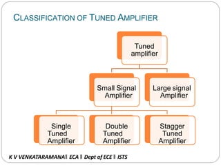
  • 8. CLASSIFICATION OF TUNED AMPLIFIER Tuned amplifier Small Signal Amplifier Single Tuned Amplifier Double Tuned Amplifier Stagger Tuned Amplifier Large signal Amplifier K V VENKATARAMANA‖ ECA ‖ Dept of ECE ‖ ISTS
  • 9. CLASSIFICATIONOFTUNED AMPLIFIERS Small Signal Tuned Amplifiers :- They are used to amplify the RF signals of small magnitude. They are further classified as: (a)Single Tuned Amplifiers:- In this we use one parallel tuned circuit in each stage. (b)Double Tuned Amplifiers:- In this we use two mutually coupled tuned circuits for every stage both of tuned circuits are tuned at same freq. (c)Stagger Tuned Amplifiers:- It is a multistage amplifier which has one parallel tuned circuit for every stage but tuned frequency for all stages K V VENKATARAMANA‖ ECA ‖ Dept of ECE ‖ ISTS
  • 10. (2) Large signal tuned amplifiers:- They are meant for amplifying large signals in which large RF power is involved & distortion level is also higher. But tuned circuit itself eliminates most of the harmonic distortion. K V VENKATARAMANA‖ ECA ‖ Dept of ECE ‖ ISTS
  • 11. SERIESRESONANT CIRCUIT •It is the circuit in which all the resistive and reactive components are in series. K V VENKATARAMANA‖ ECA ‖ Dept of ECE ‖ ISTS
  • 12. SERIESRESONANT LC K V VENKATARAMANA‖ ECA ‖ Dept of ECE ‖ ISTS
  • 13. SERIESRESONANTCIRCUIT: Impedance Of The Circuit: - Z = { R2 + (XL – Xc)2}1/2 Z = { R2 + (ωL – 1/ ωC)2}1/2 For resonant frequency:- (XL = XC ) XL = ωL = XC = 1/ ωC = 2 π frL 1 / 2 π frC K V VENKATARAMANA‖ ECA ‖ Dept of ECE ‖ ISTS
  • 14. SERIESRESONANTCIRCUIT Since at resonance, XL = Xc 2 π frL = 1 / 2ПfrC fr = 1 / 2 π √LC ωr fr = 1 / √LC K V VENKATARAMANA‖ ECA ‖ Dept of ECE ‖ ISTS
  • 16. QUALITYFACTOR: • It is voltage magnification that circuit produces at resonance is called the Q factor. Imax XL / Imin R• Voltage Magnification = = XL/ R • At Resonance = XL/R = XC/R ωrL / R = 1 / ωrRC K V VENKATARAMANA‖ ECA ‖ Dept of ECE ‖ ISTS
  • 17. THUS Qr = ωrL / R = 1/ ωrC R = 2 π fr L / R = (2 π L / R) * (1 / 2 π √LC ) = √(L/C) / R = { tan Ф = power factor of coil } tanФ K V VENKATARAMANA‖ ECA ‖ Dept of ECE ‖ ISTS
  • 18. IMPORTANTPOINTS (1) Net reactance , X = 0. (2) Impedance Z = R . (3) Power factor is unity. (4) Power expended = 6 watt. • • Current is so large & will produce large voltage across inductance & capacitance will be equal in magnitude but opposite in phase. Series resonance is called an acceptor circuit because such a circuit accepts current at one particular frequency but rejects current at other frequencies these circuit are used in Radio – receivers . K V VENKATARAMANA‖ ECA ‖ Dept of ECE ‖ ISTS
  • 19. REACTANCECURVESERIESRESONANT CIRCUIT XL = 2ΠfL X = XL - XC XC = 1 2ΠfC R fr K V VENKATARAMANA‖ ECA ‖ Dept of ECE ‖ ISTS
  • 20. PARALLELORCURRENTRESONANCE K V VENKATA RAMANA‖ ECA ‖ Dept of ECE ‖ ISTS
  • 21. PARALLELORCURRENTRESONANCE •When an inductive reactance and a capacitance are connected in parallel condition may reach under which current resonance (also known as parallel or anti- resonance ) will take palace. •The frequency at which this happened is known as resonant frequency. Current will be in resonance I reactive component of R - L branch. •IR-L sinФ R-L = Reactive component of capacitive branch, neglecting leakage reactance of capacitor C. K V VENKATA RAMANA‖ ECA ‖ Dept of ECE ‖ ISTS
  • 22. FREQUENCY V/S IMPEDANCE CURVE FOR LCR CIRCUIT K V VENKATA RAMANA‖ ECA ‖ Dept of ECE ‖ ISTS
  • 23. Inductance Quality factor (Q) 24 K V VENKATA RAMANA‖ ECA ‖ Dept of ECE ‖ ISTS
  • 24. RESONANTRESONANCE CURVE OF PARALLEL CIRCUIT : With low resistance With high resistance current fR K V VENKATA RAMANA‖ ECA ‖ Dept of ECE ‖ ISTS
  • 25. 25
  • 26. 26 K V VENKATA RAMANA‖ ECA ‖ Dept of ECE ‖ ISTS
  • 27. 27
  • 28. 92
  • 29. 29 K V VENKATA RAMANA‖ ECA ‖ Dept of ECE ‖ ISTS
  • 30. C o n d u c tan ce(R ) 30 Q t eff  Susp tan ce(L / C )
  • 31. SINGLETUNEDAMPLIFIER USINGFET K V VENKATA RAMANA‖ ECA ‖ Dept of ECE ‖ ISTS
  • 32. LIMITATION: • This tuned amplifier are required to be highly selective. But high selectivity required a tuned circuit with a high Q- factor . • A high Q- factor circuit will give a high Av but at the same time , it will give much reduced band with because bandwidth is inversely proportional to the Q- factor . • It means that tuned amplifier with reduce bandwidth may not be able to amplify equally the complete band of signals & result is poor reproduction . This is called potential instability in tuned amplifier. K V VENKATA RAMANA‖ ECA ‖ Dept of ECE ‖ ISTS
  • 33. Double tuned Amplifier: K V VENKATA RAMANA‖ ECA ‖ Dept of ECE ‖ ISTS
  • 34. 34 K V VENKATA RAMANA‖ ECA ‖ Dept of ECE ‖ ISTS
  • 35. 35
  • 36. 36 K V VENKATA RAMANA‖ ECA ‖ Dept of ECE ‖ ISTS
  • 37. 37 K V VENKATA RAMANA‖ ECA ‖ Dept of ECE ‖ ISTS
  • 38. 38 K V VENKATA RAMANA‖ ECA ‖ Dept of ECE ‖ ISTS
  • 39. 39
  • 40. 40
  • 41. 41 K V VENKATA RAMANA‖ ECA ‖ Dept of ECE ‖ ISTS
  • 42. STAGGERTUNEDAMPLIFIERS: K V VENKATA RAMANA‖ ECA ‖ Dept of ECE ‖ ISTS
  • 43. 43
  • 44. 44 K V VENKATA RAMANA‖ ECA ‖ Dept of ECE ‖ ISTS
  • 49. K V VENKATA RAMANA‖ ECA ‖ Dept of ECE ‖ ISTS
  • 50. K V VENKATA RAMANA‖ ECA ‖ Dept of ECE ‖ ISTS
  • 51. K V VENKATA RAMANA‖ ECA ‖ Dept of ECE ‖ ISTS
  • 52. K V VENKATA RAMANA‖ ECA ‖ Dept of ECE ‖ ISTS
  • 53. K V VENKATA RAMANA‖ ECA ‖ Dept of ECE ‖ ISTS
  • 54. Video Amplifiers (IC MC1550) K V VENKATA RAMANA‖ ECA ‖ Dept of ECE ‖ ISTS
  • 55. K V VENKATA RAMANA‖ ECA ‖ Dept of ECE ‖ ISTS
  • 56. APPLICATIONS OF TUNED AMPLIFIER Tuned amplifiers serve the best for two purposes: a) Selection of desired frequency. b) Amplifying the signal to a desired level. USED IN: Communication transmitters and receivers. In filter design :--Band Pass, low pass, High pass and band reject filter design. K V VENKATA RAMANA‖ ECA ‖ Dept of ECE ‖ ISTS
  • 57. ADVANTAGES It provides high selectivity. It has small collector voltage. Power loss is also less. Signal to noise ratio of O/P is good. They are well suited for radio transmitters and receivers . K V VENKATA RAMANA‖ ECA ‖ Dept of ECE ‖ ISTS
  • 58. DISADVANTAGES They are not suitable to amplify audio frequencies. If the band of frequency is increase then design becomes complex. Since they use inductors and capacitors as tuning elements, the circuit is bulky and costly. K V VENKATA RAMANA‖ ECA ‖ Dept of ECE ‖ ISTS
  • 59. Thank you K V VENKATA RAMANA‖ ECA ‖ Dept of ECE ‖ ISTS