SlideShare a Scribd company logo
UML U M L(Unified Modeling Language)BYCh. Vishwa MohanProject ManagerVision Krest Embedded Systems
Software Development Life Cycle (SDLC)Requirement Definition Requirement Analysis. System Design Prototyping ConstructionIntegration Testing Implementation Documentation Maintenance.
What is a Process?
What are the Life Cycle Types ? Structured MethodsCode and Fix (Traditional) WaterfallSpiralWard & Mellor (Real Time & Embedded Systems)Object Oriented MethodsOOA/OOD By Coad & YourdonOOD By BoochOMT By RambaughOOSE by Jacobson
Drawbacks of Traditional Methods ! Adaptability to change is very poor. Bugs. Person Dependency No way to communicate with team members. No way to model the system Limited user involvement. Persons involved in the analysis will required to go for coding and further phases.
Benefits of the Object Oriented Methodologies: New requirements can be added at later stage and their integration will be very easy. It’s possible to deal with more complex systems.Easy way to make communication between software developers and experts. Seen over the whole of their lifetime, OO models are more stable and thus easier to modify. OO abstraction allows increases reusability of work outcomes. Finally it’s more fun.
Steps involved in the OO  Software Development:Identify the objects and their attributes. Study operations associated with the objects. Design classes from objects having similar characteristics. Establish relationship between classes. Implement the classes and relationships between them.
UMLWhat is Model ? Representation in a certain medium of some thing in the same or other medium. A model represents the blueprint of the system. It is an abstract representation of a system. What is In a Model ? Semantics:It captures the classes, associations, states, use cases and messages. Visual Representation:How to represent model elements. Different tool vendors shows different representation for the same model.
What is UML ? UML is a general purpose visual modeling language that is used to specify, visualize, construct, and document the artifacts of a software intensive system. UML enables system builders to create blue prints that capture their vision in a standard easy-to understand way and communication them to others.UML can be used with all processes, throughout the development life cycle, and across different implementation technologies.UML captures the static and dynamic behavior of systems.
What is a Visual Modeling ?Basically, the modeling captures the essential parts of the system. Computer system basically automate business processes.  However, it’s not easy to build software systems on time and within budget.Building a complex software system requires blueprint.  You don’t construct a building without a blueprint.  Visual modeling is the blueprint for software systems.Finally we can say, Visual Modeling is the key to successful software development.
What is a Visual Modeling?
Benefits of Visual Modeling?Visual Modeling captures business processUse case analysis is a technique to capture business process from users perspective. Visual Modeling is a communication tool.Use visual modeling to capture business objects and logic. Use visual modeling to analyze and design your application. Visual Modeling manages complexity.   Visual Modeling defines software architecture. With the help of Visual modeling language your model your system independent of implementation language. Visual Modeling promotes reuse. Here Visual Modeling can be used as component browser and it can also be used to model component assembly.
UML Concepts are:The UML may be used to:Display the boundary of a system & its major functions using use cases and actors
Illustrate use case realizations with interaction diagrams
Represent a static structure of a system using class diagrams
Model the behavior of objects with state transition diagrams
Reveal the physical implementation architecture with component & deployment diagrams
Extend your functionality with stereotypesOO Software Development with UMLInside the UML, you can not only describes data and functions; their interconnections and their relationships with the surrounding world (I.e., with other data and functional units) can be defined in a differential way. This dependency relationship helps the programmers from development to coding phase. It helps the programmers higher degree of complexity. What are the Benefits of UML?Reverse Engineering Re-engineering Forward EngineeringDocumentation DevelopmentSource Code Generation.
Different Diagrams in UML Use Case Diagram Class Diagram Sequence Diagram Collaboration Diagram State Transition DiagramActivity Diagram Component Diagram Module Diagram Deployment Diagram. Presentation Diagram
Uml
UML ViewsStatic ViewsDynamic ViewsStatic View:
Static View is the foundation of UML. It captures the object Structure. It doesn’t contains details of dynamic behavior.
The key elements in the Static View are
Classifier
RelationshipsClassifiers: A classifier is a modeling element, that defines the structure and behavior. Classifiers are: ClassesInterfacesData typesNodes Actors Signal Behavioral things are classified by other classifiers use cases and signals. A Classifier have identity, state, behavior & relationships. Relationships among classifiers are: Association, Generalization, various kinds of dependency including Realization and Usage.
Classes: A Class defines a set of objects that have a state and behavior. State is described by its attributes and associations. A Class has unique name within its container. The class has a visibility with respect to its container. If a class is a part of package then you can represent the class preceded with package name. Eg: HouseHoldApp::WashingMachineUse Case DiagramUse Case Diagrams are used to model the interaction of system with the external actors.A use case is a description of a system’s behavior from a users standpoint. It consists of group of actors, a set of use cases.Use case diagram is used to Modeling the system from user point of viewIt shows the boundaries between system and the outside world. It is a powerful tool to gather functional requirements. Used to identify external users. An Actor is a stereotype of class.It is an object outside the scope of the system under discussion. In UML three types of relationships between use cases are defined: IncludeExtendGeneralization (Uses)Communication between Actors and Use cases can either be Unidirectionalor Bi-directional.
ActorRegistrarFacultyStudentBilling SystemAn actor is someone or some thing that must interact with the system under development.An Actor is a stereo type of class. An actor is represented with a  sticky man.
Use CaseMaintain ScheduleMaintain CurriculumRequest Course RosterA use case is a pattern of behavior the system exhibitsEach use case is a sequence of related transactions performed by an actor and the system in a dialogue.
 Use case represented with oval. Actors are examined to determine their needsRegistrar -- maintain the curriculum
Professor -- request roster
Student -- maintain schedule
Billing System -- receive billing information from registrationUse Case DiagramRequest Course RosterProfessorStudentMaintain ScheduleMaintain CurriculumFaculty  RegistrarUse case diagrams are created to visualize the relation ships between actors and use cases.
<<uses>>Register for courses<<uses>>Logon validationMaintain curriculumUses and Extends Use Case RelationshipAs the use cases are documented, other use case relationships may be discoveredA uses relationship shows behavior that is common to one or more use cases.
An extends relationship shows optional behavior Use Case Diagram :
Use Case RealizationThe use case diagram presents an outside view of the systemInteraction diagrams describe how use cases are realized as interactions among societies of objectsTwo types of interaction diagramsSequence diagrams
Collaboration diagramsClass Diagram: Class diagram is the heart of OOAD. A class diagram shows the existence of classes and their relationships in the logical view of a system. The class diagram depicts the static structure of a system. UML modeling elements in this diagram are:  Classes and their structure and behavior (attributes & operations)Their Relationships with other classes. Multiplicity and Navigation indicator.Role NamesClass: The common noun corresponding to every object identified in the problem domain is a class.A class is a collection of objects with common structure, common behavior, common relationships and common semantics. Classes are found by examining the objects in sequence and collaboration diagram
Class DiagramClasses can represent Physical thing (Airplane) Business thing (order, invoice)Logical thing (broadcasting schedule)Application thing (Button, Cerror)Computer thing (hash table)Behavior thing (A Task)Types of Classes you can showConcrete Class
Abstract Class
Template Class
Interface Class
Utility ClassClassesScheduleAlgorithmRegistrationManagerRegistrationFormProfessorCourseStudentCourseOfferingInside UML a class is represented with three compartments: First compartment represented with class name.Second is represented with attributesFinally third compartment is used to represent the behaviors of a class.
AttributesCourseOfferingnumberloationtimeThe structure of a class is represented by its attributes.Attributes may be found by examining class definitions, the problem requirements, and by applying domain knowledge.   Each course offeringhas a number, location and time
Operationsregistration registration formmanagerRegistrationManager3: add course(joe, math 01)addCourse(Student,Course)The behavior of a class is represented by its operations. Operations may be found by examining interaction diagrams.
Relationships	Relationships provides pathway for communication between objects. Sequence and/or collaboration diagrams are examined to determine what links between objects need to exist to accomplish the behavior. If two objects need to “talk” there must be a link between them.Three types of relationships are:Association, Aggregation and Dependency.
Interfaces: Interfaces does not have attributes. So there is no state for interfaces. Interfaces doesn’t have outgoing associations that are visible to it.You can draw the following relationships with interfacesGeneralization
Realization
AssociationAn Interface is represented by a Circle with small line attached to it. Interface
Association 	An association establishes relationship between two classes. It is a bi-directional. Data can flow both directions across association. The frequency of association is called Multiplicity. You can apply constraints on association (eg: ordered, or  etc., ) One way of association is called directed association, in which only one side knows the other, but not vice versa. Different types of associations are: Recursive Association
Attributed Association
Qualified Association
Derived Association
Directed Association   Aggregation & Dependency	An aggregation is a stronger form of relationship where the relationship is between a whole and its parts. An aggregation is shown as a line connecting the related classes with a diamond next to the class representing the whole. A dependency relationship is a weaker form of relationship showing a relationship between a client and a supplier where the client does not have semantic knowledge of the supplier.A dependency is shown as a dashed line pointing from the client to the supplier.Finding Relationships	RegistrationMgrRegistrationMgr.NET : Course3: add student(joe)CourseRelationships are discovered by examining the interaction diagrams. If two objects must talk there must be a path way for communication.  Typical Class Diagram
Multiplicity	Multiplicity defines how many objects participate in a relationship.  It defines the number of instances of one class related to ONE instance of the other class.
For each association and aggregation, there are two multiplicity decisions to make:  one for each end of the relationship
A class also has multiplicity. Navigation	Although association and aggregation are bi-directional by default, it is often desirable to restrict navigation to one direction. If navigation is restricted, an arrowhead is added to indicate the direction of the navigation. Concurrency	Inside class diagram, you can specify the attribute concurrency for each method. This concurrency states that it’s semantic of concurrent calls to the same passive instance. Basically it addresses the synchronization problem in the case of multiple threads. The different concurrency options are:Sequential
Guarded
Concurrent	Inheritance 	Inheritance is a relationships between a superclass and its subclass. There are two ways to find inheritance:Generalization
Specialization. Common attributes, operations, and/or relationships are shown at the highest applicable level in the hierarchy.
Inheritance Representation
Links 	Link: A Link is an instance of an association. It connects objects rather then classes. Link name should be under lined. Mohan:FacultyJayaMukhi:BatchTeaches
StereotypesStereotype and Constraints are two constructs the UML provided for extending the language. Stereotype is nothing but adding new features to the existing elements and make is as new element.
Stereotypes can be sued to extend the UML notational elements. Stereotypes may be used to classify and extend associations, inheritance relationships, classes, and components. Examples of stereotypes: Class Stereotypes: Actor, boundary, entity, utility, exception. Inheritance Stereotypes: uses and extends. Component Stereotypes: subsystem.
Ad

More Related Content

What's hot (20)

Activity diagram
Activity diagramActivity diagram
Activity diagram
LOKENDRA PRAJAPATI
 
Class diagrams
Class diagramsClass diagrams
Class diagrams
Nadia_Nazeer
 
UML (Unified Modeling Language)
UML (Unified Modeling Language)UML (Unified Modeling Language)
UML (Unified Modeling Language)
Nguyen Tuan
 
State Diagrams
State DiagramsState Diagrams
State Diagrams
Vaidik Trivedi
 
Use case Diagram
Use case Diagram Use case Diagram
Use case Diagram
Rahul Pola
 
UML
UMLUML
UML
iQra Rafaqat
 
UML Diagrams
UML DiagramsUML Diagrams
UML Diagrams
Kartik Raghuvanshi
 
Activity Diagram
Activity DiagramActivity Diagram
Activity Diagram
Ashesh R
 
Uml
UmlUml
Uml
Sulman Ahmed
 
Activity diagram
Activity diagramActivity diagram
Activity diagram
bhupendra kumar
 
CS8592-OOAD Lecture Notes Unit-2
CS8592-OOAD Lecture Notes Unit-2CS8592-OOAD Lecture Notes Unit-2
CS8592-OOAD Lecture Notes Unit-2
Gobinath Subramaniam
 
Oomd unit1
Oomd unit1Oomd unit1
Oomd unit1
VivekChaudhary93
 
Overview of UML Diagrams
Overview of UML DiagramsOverview of UML Diagrams
Overview of UML Diagrams
Manish Kumar
 
Object Oriented Analysis Design using UML
Object Oriented Analysis Design using UMLObject Oriented Analysis Design using UML
Object Oriented Analysis Design using UML
Ajit Nayak
 
Collaboration diagram- UML diagram
Collaboration diagram- UML diagram Collaboration diagram- UML diagram
Collaboration diagram- UML diagram
Ramakant Soni
 
Uml - An Overview
Uml - An OverviewUml - An Overview
Uml - An Overview
Raj Thilak S
 
Object diagram
Object diagramObject diagram
Object diagram
Rahul Pola
 
State Machine Diagram
State Machine DiagramState Machine Diagram
State Machine Diagram
Niloy Rocker
 
CHAPTER 6 REQUIREMENTS MODELING: SCENARIO based Model , Class based moddel
CHAPTER 6 REQUIREMENTS MODELING: SCENARIO based Model , Class based moddelCHAPTER 6 REQUIREMENTS MODELING: SCENARIO based Model , Class based moddel
CHAPTER 6 REQUIREMENTS MODELING: SCENARIO based Model , Class based moddel
mohamed khalaf alla mohamedain
 
ADO .Net
ADO .Net ADO .Net
ADO .Net
DrSonali Vyas
 

Similar to Uml (20)

Software Engineering Tools and Practices.pdf
Software Engineering Tools and Practices.pdfSoftware Engineering Tools and Practices.pdf
Software Engineering Tools and Practices.pdf
MeagGhn
 
Object oriented analysis and design unit- ii
Object oriented analysis and design unit- iiObject oriented analysis and design unit- ii
Object oriented analysis and design unit- ii
Shri Shankaracharya College, Bhilai,Junwani
 
ASP.NET System design 2
ASP.NET System design 2ASP.NET System design 2
ASP.NET System design 2
Sisir Ghosh
 
Object-Oriented Analysis and Design report
Object-Oriented Analysis and Design reportObject-Oriented Analysis and Design report
Object-Oriented Analysis and Design report
ritikapoudel2017
 
Ch 2.1
Ch 2.1Ch 2.1
Ch 2.1
mahammed rashid
 
432
432432
432
Sushath SimplytheBest
 
UML and Software Modeling Tools.pptx
UML and Software Modeling Tools.pptxUML and Software Modeling Tools.pptx
UML and Software Modeling Tools.pptx
Nwabueze Obioma
 
Design UML diagrams
Design UML diagramsDesign UML diagrams
Design UML diagrams
Neeraj Kaushik
 
Design UML diagrams
Design UML diagramsDesign UML diagrams
Design UML diagrams
Neeraj Kaushik
 
Ooad overview
Ooad overviewOoad overview
Ooad overview
Dr. C.V. Suresh Babu
 
Ooad Overview
Ooad OverviewOoad Overview
Ooad Overview
Dang Tuan
 
Unified Modeling Language
Unified Modeling LanguageUnified Modeling Language
Unified Modeling Language
surana college
 
Object oriented analysis and design unit- iv
Object oriented analysis and design unit- ivObject oriented analysis and design unit- iv
Object oriented analysis and design unit- iv
Shri Shankaracharya College, Bhilai,Junwani
 
Introduction to Modeling Java and UML
Introduction to Modeling Java and UMLIntroduction to Modeling Java and UML
Introduction to Modeling Java and UML
Dang Tuan
 
Intro Uml
Intro UmlIntro Uml
Intro Uml
Kris der Rose
 
Ooad
OoadOoad
Ooad
gantib
 
Uml
UmlUml
Uml
parag
 
Introduction to Object orientation , Modeling as a Design Technique Modeling ...
Introduction to Object orientation , Modeling as a Design Technique Modeling ...Introduction to Object orientation , Modeling as a Design Technique Modeling ...
Introduction to Object orientation , Modeling as a Design Technique Modeling ...
DhwaniDesai21
 
Introduction to Unified Modeling Language
Introduction to Unified Modeling LanguageIntroduction to Unified Modeling Language
Introduction to Unified Modeling Language
AMITJain879
 
UML Design
UML DesignUML Design
UML Design
Debashis Biswas
 
Software Engineering Tools and Practices.pdf
Software Engineering Tools and Practices.pdfSoftware Engineering Tools and Practices.pdf
Software Engineering Tools and Practices.pdf
MeagGhn
 
ASP.NET System design 2
ASP.NET System design 2ASP.NET System design 2
ASP.NET System design 2
Sisir Ghosh
 
Object-Oriented Analysis and Design report
Object-Oriented Analysis and Design reportObject-Oriented Analysis and Design report
Object-Oriented Analysis and Design report
ritikapoudel2017
 
UML and Software Modeling Tools.pptx
UML and Software Modeling Tools.pptxUML and Software Modeling Tools.pptx
UML and Software Modeling Tools.pptx
Nwabueze Obioma
 
Ooad Overview
Ooad OverviewOoad Overview
Ooad Overview
Dang Tuan
 
Unified Modeling Language
Unified Modeling LanguageUnified Modeling Language
Unified Modeling Language
surana college
 
Introduction to Modeling Java and UML
Introduction to Modeling Java and UMLIntroduction to Modeling Java and UML
Introduction to Modeling Java and UML
Dang Tuan
 
Introduction to Object orientation , Modeling as a Design Technique Modeling ...
Introduction to Object orientation , Modeling as a Design Technique Modeling ...Introduction to Object orientation , Modeling as a Design Technique Modeling ...
Introduction to Object orientation , Modeling as a Design Technique Modeling ...
DhwaniDesai21
 
Introduction to Unified Modeling Language
Introduction to Unified Modeling LanguageIntroduction to Unified Modeling Language
Introduction to Unified Modeling Language
AMITJain879
 
Ad

More from Vishwa Mohan (15)

OPC Unified Architecture
OPC Unified ArchitectureOPC Unified Architecture
OPC Unified Architecture
Vishwa Mohan
 
jQuery
jQueryjQuery
jQuery
Vishwa Mohan
 
WPF
WPFWPF
WPF
Vishwa Mohan
 
Wwf
WwfWwf
Wwf
Vishwa Mohan
 
Da package usersguide
Da package usersguideDa package usersguide
Da package usersguide
Vishwa Mohan
 
Dareadme
DareadmeDareadme
Dareadme
Vishwa Mohan
 
CSharp Presentation
CSharp PresentationCSharp Presentation
CSharp Presentation
Vishwa Mohan
 
Linq
LinqLinq
Linq
Vishwa Mohan
 
Xml
XmlXml
Xml
Vishwa Mohan
 
Real Time Systems &amp; RTOS
Real Time Systems &amp; RTOSReal Time Systems &amp; RTOS
Real Time Systems &amp; RTOS
Vishwa Mohan
 
Embedded Linux
Embedded LinuxEmbedded Linux
Embedded Linux
Vishwa Mohan
 
Introduction To Embedded Systems
Introduction To Embedded SystemsIntroduction To Embedded Systems
Introduction To Embedded Systems
Vishwa Mohan
 
Microsoft.Net
Microsoft.NetMicrosoft.Net
Microsoft.Net
Vishwa Mohan
 
Zig Bee
Zig BeeZig Bee
Zig Bee
Vishwa Mohan
 
WCF
WCFWCF
WCF
Vishwa Mohan
 
Ad

Uml

  • 1. UML U M L(Unified Modeling Language)BYCh. Vishwa MohanProject ManagerVision Krest Embedded Systems
  • 2. Software Development Life Cycle (SDLC)Requirement Definition Requirement Analysis. System Design Prototyping ConstructionIntegration Testing Implementation Documentation Maintenance.
  • 3. What is a Process?
  • 4. What are the Life Cycle Types ? Structured MethodsCode and Fix (Traditional) WaterfallSpiralWard & Mellor (Real Time & Embedded Systems)Object Oriented MethodsOOA/OOD By Coad & YourdonOOD By BoochOMT By RambaughOOSE by Jacobson
  • 5. Drawbacks of Traditional Methods ! Adaptability to change is very poor. Bugs. Person Dependency No way to communicate with team members. No way to model the system Limited user involvement. Persons involved in the analysis will required to go for coding and further phases.
  • 6. Benefits of the Object Oriented Methodologies: New requirements can be added at later stage and their integration will be very easy. It’s possible to deal with more complex systems.Easy way to make communication between software developers and experts. Seen over the whole of their lifetime, OO models are more stable and thus easier to modify. OO abstraction allows increases reusability of work outcomes. Finally it’s more fun.
  • 7. Steps involved in the OO Software Development:Identify the objects and their attributes. Study operations associated with the objects. Design classes from objects having similar characteristics. Establish relationship between classes. Implement the classes and relationships between them.
  • 8. UMLWhat is Model ? Representation in a certain medium of some thing in the same or other medium. A model represents the blueprint of the system. It is an abstract representation of a system. What is In a Model ? Semantics:It captures the classes, associations, states, use cases and messages. Visual Representation:How to represent model elements. Different tool vendors shows different representation for the same model.
  • 9. What is UML ? UML is a general purpose visual modeling language that is used to specify, visualize, construct, and document the artifacts of a software intensive system. UML enables system builders to create blue prints that capture their vision in a standard easy-to understand way and communication them to others.UML can be used with all processes, throughout the development life cycle, and across different implementation technologies.UML captures the static and dynamic behavior of systems.
  • 10. What is a Visual Modeling ?Basically, the modeling captures the essential parts of the system. Computer system basically automate business processes. However, it’s not easy to build software systems on time and within budget.Building a complex software system requires blueprint. You don’t construct a building without a blueprint. Visual modeling is the blueprint for software systems.Finally we can say, Visual Modeling is the key to successful software development.
  • 11. What is a Visual Modeling?
  • 12. Benefits of Visual Modeling?Visual Modeling captures business processUse case analysis is a technique to capture business process from users perspective. Visual Modeling is a communication tool.Use visual modeling to capture business objects and logic. Use visual modeling to analyze and design your application. Visual Modeling manages complexity. Visual Modeling defines software architecture. With the help of Visual modeling language your model your system independent of implementation language. Visual Modeling promotes reuse. Here Visual Modeling can be used as component browser and it can also be used to model component assembly.
  • 13. UML Concepts are:The UML may be used to:Display the boundary of a system & its major functions using use cases and actors
  • 14. Illustrate use case realizations with interaction diagrams
  • 15. Represent a static structure of a system using class diagrams
  • 16. Model the behavior of objects with state transition diagrams
  • 17. Reveal the physical implementation architecture with component & deployment diagrams
  • 18. Extend your functionality with stereotypesOO Software Development with UMLInside the UML, you can not only describes data and functions; their interconnections and their relationships with the surrounding world (I.e., with other data and functional units) can be defined in a differential way. This dependency relationship helps the programmers from development to coding phase. It helps the programmers higher degree of complexity. What are the Benefits of UML?Reverse Engineering Re-engineering Forward EngineeringDocumentation DevelopmentSource Code Generation.
  • 19. Different Diagrams in UML Use Case Diagram Class Diagram Sequence Diagram Collaboration Diagram State Transition DiagramActivity Diagram Component Diagram Module Diagram Deployment Diagram. Presentation Diagram
  • 21. UML ViewsStatic ViewsDynamic ViewsStatic View:
  • 22. Static View is the foundation of UML. It captures the object Structure. It doesn’t contains details of dynamic behavior.
  • 23. The key elements in the Static View are
  • 25. RelationshipsClassifiers: A classifier is a modeling element, that defines the structure and behavior. Classifiers are: ClassesInterfacesData typesNodes Actors Signal Behavioral things are classified by other classifiers use cases and signals. A Classifier have identity, state, behavior & relationships. Relationships among classifiers are: Association, Generalization, various kinds of dependency including Realization and Usage.
  • 26. Classes: A Class defines a set of objects that have a state and behavior. State is described by its attributes and associations. A Class has unique name within its container. The class has a visibility with respect to its container. If a class is a part of package then you can represent the class preceded with package name. Eg: HouseHoldApp::WashingMachineUse Case DiagramUse Case Diagrams are used to model the interaction of system with the external actors.A use case is a description of a system’s behavior from a users standpoint. It consists of group of actors, a set of use cases.Use case diagram is used to Modeling the system from user point of viewIt shows the boundaries between system and the outside world. It is a powerful tool to gather functional requirements. Used to identify external users. An Actor is a stereotype of class.It is an object outside the scope of the system under discussion. In UML three types of relationships between use cases are defined: IncludeExtendGeneralization (Uses)Communication between Actors and Use cases can either be Unidirectionalor Bi-directional.
  • 27. ActorRegistrarFacultyStudentBilling SystemAn actor is someone or some thing that must interact with the system under development.An Actor is a stereo type of class. An actor is represented with a sticky man.
  • 28. Use CaseMaintain ScheduleMaintain CurriculumRequest Course RosterA use case is a pattern of behavior the system exhibitsEach use case is a sequence of related transactions performed by an actor and the system in a dialogue.
  • 29. Use case represented with oval. Actors are examined to determine their needsRegistrar -- maintain the curriculum
  • 32. Billing System -- receive billing information from registrationUse Case DiagramRequest Course RosterProfessorStudentMaintain ScheduleMaintain CurriculumFaculty RegistrarUse case diagrams are created to visualize the relation ships between actors and use cases.
  • 33. <<uses>>Register for courses<<uses>>Logon validationMaintain curriculumUses and Extends Use Case RelationshipAs the use cases are documented, other use case relationships may be discoveredA uses relationship shows behavior that is common to one or more use cases.
  • 34. An extends relationship shows optional behavior Use Case Diagram :
  • 35. Use Case RealizationThe use case diagram presents an outside view of the systemInteraction diagrams describe how use cases are realized as interactions among societies of objectsTwo types of interaction diagramsSequence diagrams
  • 36. Collaboration diagramsClass Diagram: Class diagram is the heart of OOAD. A class diagram shows the existence of classes and their relationships in the logical view of a system. The class diagram depicts the static structure of a system. UML modeling elements in this diagram are: Classes and their structure and behavior (attributes & operations)Their Relationships with other classes. Multiplicity and Navigation indicator.Role NamesClass: The common noun corresponding to every object identified in the problem domain is a class.A class is a collection of objects with common structure, common behavior, common relationships and common semantics. Classes are found by examining the objects in sequence and collaboration diagram
  • 37. Class DiagramClasses can represent Physical thing (Airplane) Business thing (order, invoice)Logical thing (broadcasting schedule)Application thing (Button, Cerror)Computer thing (hash table)Behavior thing (A Task)Types of Classes you can showConcrete Class
  • 41. Utility ClassClassesScheduleAlgorithmRegistrationManagerRegistrationFormProfessorCourseStudentCourseOfferingInside UML a class is represented with three compartments: First compartment represented with class name.Second is represented with attributesFinally third compartment is used to represent the behaviors of a class.
  • 42. AttributesCourseOfferingnumberloationtimeThe structure of a class is represented by its attributes.Attributes may be found by examining class definitions, the problem requirements, and by applying domain knowledge. Each course offeringhas a number, location and time
  • 43. Operationsregistration registration formmanagerRegistrationManager3: add course(joe, math 01)addCourse(Student,Course)The behavior of a class is represented by its operations. Operations may be found by examining interaction diagrams.
  • 44. Relationships Relationships provides pathway for communication between objects. Sequence and/or collaboration diagrams are examined to determine what links between objects need to exist to accomplish the behavior. If two objects need to “talk” there must be a link between them.Three types of relationships are:Association, Aggregation and Dependency.
  • 45. Interfaces: Interfaces does not have attributes. So there is no state for interfaces. Interfaces doesn’t have outgoing associations that are visible to it.You can draw the following relationships with interfacesGeneralization
  • 47. AssociationAn Interface is represented by a Circle with small line attached to it. Interface
  • 48. Association An association establishes relationship between two classes. It is a bi-directional. Data can flow both directions across association. The frequency of association is called Multiplicity. You can apply constraints on association (eg: ordered, or etc., ) One way of association is called directed association, in which only one side knows the other, but not vice versa. Different types of associations are: Recursive Association
  • 52. Directed Association Aggregation & Dependency An aggregation is a stronger form of relationship where the relationship is between a whole and its parts. An aggregation is shown as a line connecting the related classes with a diamond next to the class representing the whole. A dependency relationship is a weaker form of relationship showing a relationship between a client and a supplier where the client does not have semantic knowledge of the supplier.A dependency is shown as a dashed line pointing from the client to the supplier.Finding Relationships RegistrationMgrRegistrationMgr.NET : Course3: add student(joe)CourseRelationships are discovered by examining the interaction diagrams. If two objects must talk there must be a path way for communication. Typical Class Diagram
  • 53. Multiplicity Multiplicity defines how many objects participate in a relationship. It defines the number of instances of one class related to ONE instance of the other class.
  • 54. For each association and aggregation, there are two multiplicity decisions to make: one for each end of the relationship
  • 55. A class also has multiplicity. Navigation Although association and aggregation are bi-directional by default, it is often desirable to restrict navigation to one direction. If navigation is restricted, an arrowhead is added to indicate the direction of the navigation. Concurrency Inside class diagram, you can specify the attribute concurrency for each method. This concurrency states that it’s semantic of concurrent calls to the same passive instance. Basically it addresses the synchronization problem in the case of multiple threads. The different concurrency options are:Sequential
  • 57. Concurrent Inheritance Inheritance is a relationships between a superclass and its subclass. There are two ways to find inheritance:Generalization
  • 58. Specialization. Common attributes, operations, and/or relationships are shown at the highest applicable level in the hierarchy.
  • 60. Links Link: A Link is an instance of an association. It connects objects rather then classes. Link name should be under lined. Mohan:FacultyJayaMukhi:BatchTeaches
  • 61. StereotypesStereotype and Constraints are two constructs the UML provided for extending the language. Stereotype is nothing but adding new features to the existing elements and make is as new element.
  • 62. Stereotypes can be sued to extend the UML notational elements. Stereotypes may be used to classify and extend associations, inheritance relationships, classes, and components. Examples of stereotypes: Class Stereotypes: Actor, boundary, entity, utility, exception. Inheritance Stereotypes: uses and extends. Component Stereotypes: subsystem.
  • 63. ConstraintsA Constraint is an expression which restricts the possible contents, states are the semantics of a model element which must always be satisfied. Constraints are always enclosed in braces. The below represents constraint on association. Bank Teller CustomerServers {ordered} Chooses.NET Course Student{Or}Java CourseChooses
  • 64. Sequence Diagram:Objects are usually identified by studying the problem domain. The main tools to study the objects behavior are: Sequence Diagram
  • 67. Collaboration DiagramSequence diagram is a tool to model the dynamic behavior of the system. It shows a graphical method to illustrate the sequence of events that occur one particular execution of the system.
  • 68. The sequence diagram shows the interaction between objects in a time sequence.
  • 69. The messages can be : Simple, Synchronous, Asynchronous and Reply messages. Representation of MessagesThe below are the symbols of the message representations.
  • 70. Sequence Diagramregistration registration math 101math 101 : Studentformmanagersection 11: fill in info2: submit3: add course(joe, math 01)4: are you open?5: are you open?6: add (joe)7: add (joe)A Sequence diagram displays the object interaction arranged in a time sequence.
  • 72. State Transition Diagram A state transition diagram shows: The life history of a given class.
  • 73. The events that cause a transition from one state to another.
  • 74. The actions that result from a state change. State transition diagrams are created for objects with significant dynamic behavior.
  • 76. Collaboration DiagramThe Collaboration diagram shows a set of interactions between selected objects in a specific limited situation (context), focusing on the relations between the objects and their topography. A Collaboration diagram displays the object interactions organized around objects and their links to one another.
  • 77. The collaboration diagram shows the chronological sequence of the messages, their names, responses and their arguments. Like sequence diagram collaboration diagram also shows the object interaction. The sequence diagram is organized according to time and collaboration diagram is organized according to space.
  • 78. The sequence diagram and collaboration diagram are similar in fact semantically they are equivalent. You can turn a sequence diagram into equivalent collaboration diagram and vice versa. Collaboration Diagram
  • 79. Component DiagramComponent diagram illustrate the organizations and dependencies among software components. A component may be: A source Code Component
  • 80. A run time Component
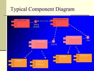
  • 81. An executable component. Typical Component Diagram
  • 82. Deployment DiagramRegistrationDatabaseMain LibraryBuildingDormThe deployment diagram shows the configuration or run-time processing elements and the software processes living on them. The deployment diagram visualizes the distribution of components across the enterprise.

Editor's Notes

  • #42: Sequential:Only one call to an instance may be outstanding at once. Guarded: Multiple calls from concurrent threads may occur simultaneously to one instance, but only one is allowed to commence. The others are blocked until the performance of the first operation is complete. (Designers to ensure that deadlocks can’t occur)Concurrent: Multiple calls from concurrent threads may occur simultaneously to one instance on any concurrent operation. All of them may process concurrently with correct semantics. (Inside the method implementation synchronization problems are correctly addressed.)