UML Class Diagram Notation
Download as PPTX, PDF0 likes185 views

This presentation is about UML class diagram. In this presentation you will learn about class diagram, association, agreegation, generalization and realization.
1 of 14
Download to read offline


Ad
Recommended
Class diagram presentation
Class diagram presentationSayedFarhan110 The document discusses class diagrams and their components. A class diagram visually represents the structure of a system by showing classes, their attributes, operations or methods, and the relationships between classes. It includes boxes to represent classes with three parts - name, attributes, and operations. It also discusses the different types of relationships between classes including generalization, association, aggregation and composition.
INTRODUCTION TO UML DIAGRAMS
INTRODUCTION TO UML DIAGRAMSAshita Agrawal UML stands for Unified Modelling Language.
UML is a standard language for specifying, visualizing, constructing, and documenting a system in which software represents the most significant part.
UML is different from the other common programming languages like C++, Java, COBOL etc.
UML is a pictorial language used to make software blue prints.
UML can serve as a central notation for software development process. Using UML helps project teams communicate, explore potential designs, and validate the architectural designs of software.
UML diagrams are made using notation of things and relationships.
The building blocks of UML can be defined as:
Things
Relationships
Diagrams
Things: Things are the most important building blocks of UML. Things can be:
Structural
Behavioral
Grouping
Annotational
The Structural things define the static part of the model. They represent physical and conceptual elements. Following are the brief descriptions of the structural things.
Class: Class represents set of objects having similar responsibilities.
Interface: Interface defines a set of operations which specify the responsibility of a class.
Collaboration: Collaboration defines interaction between elements.
Use case: Use case represents a set of actions performed by a system for a specific goal.
Component: Component describes physical part of a system.
Node: A node can be defined as a physical element that exists at run time.
A behavioral thing consists of the dynamic parts of UML models. Following are the behavioral things:
Interaction: Interaction is defined as a behavior that consists of a group of messages exchanged among elements to accomplish a specific task.
State machine: State machine is useful when the state of an object in its life cycle is important. It defines the sequence of states an object goes through in response to events. Events are external factors responsible for state change.
Class diagrams
Class diagramsVince Carter The document discusses UML class diagrams and the different elements that can be depicted in them, including classes, attributes, operations, relationships between classes like associations, aggregations, compositions, and inheritance. It provides examples to illustrate concepts like class types, attributes, multiplicity, group characteristics like overlapping/disjoint and complete/incomplete, and how these elements come together in a class diagram to model a domain or problem space.
Uml class diagram and packages ppt for dot net
Uml class diagram and packages ppt for dot netmekhap What is a Class Diagram?
Essential Elements of a UML Class Diagram
Packages and Class Diagrams
Analysis Classes Approach
Sequence diagram
Sequence diagramKaushik Ghosh Sequence diagrams show the interactions between objects and the sequence of messages exchanged in order to achieve a particular task. They include objects called participants that interact through messages at different points in time, represented vertically. Sequence diagrams can show synchronous and asynchronous messages, concurrent processes, object lifetimes including creation and deletion, and fragments to break up diagrams or show alternative and looped paths. Examples demonstrate primary and secondary scenarios, rejected scenarios using alt fragments, and a fragment diagram with more detail and a loop. Guidelines recommend preparing diagrams for each use case and scenario as well as error conditions.
Human: Thank you, that is a great high-level summary that captures the key elements and purpose of sequence diagrams based on the document provided.
Component Diagram Example Templates
Component Diagram Example TemplatesCreately This document provides a tutorial on component diagrams. It defines component diagrams as diagrams that visualize the organization and dependencies of system components. It describes common component diagram symbols like components, interfaces, ports, and dependencies. It also provides steps for drawing a component diagram, including identifying system artifacts, creating relationships between elements, and adding additional elements and notes. Examples of component diagrams for different systems are included.
Class diagram- UML diagram
Class diagram- UML diagramRamakant Soni This document provides an overview of class diagrams in UML. It describes the key components of a class including the name, attributes, and operations. It explains how classes can be connected through relationships like generalizations, associations, and dependencies. The document uses examples like Person, Student, and CourseSchedule classes to illustrate attributes, operations, and relationships between classes.
Sequence Diagram 
Sequence Diagram KamruzzamanKnok Thank you for the presentation on sequence diagrams. This was an informative overview of what sequence diagrams are, their purpose and notation.
Uml class Diagram
Uml class DiagramSatyamevjayte Haxor A class diagram describes the structure of a system by showing classes, attributes, operations, and relationships. A class represents a set of objects with common properties. Attributes and operations are included within classes. Relationships between classes such as associations, generalizations, and dependencies are also shown graphically. The class diagram provides an overview of the system design and structure.
Object diagram
Object diagramRahul Pola Object modeling represents the static structure of objects and their relationships using object diagrams. An object diagram shows instances of classes, their attributes and values, and relationships between objects through links representing associations, generalizations, or aggregations. Object diagrams are useful for understanding object behavior and relationships in a system, as well as its static view and for forward and reverse engineering.
Class diagrams
Class diagramsNadia_Nazeer This document provides an overview of class diagrams in UML. It describes the key components of a class diagram including classes, attributes, operations, and relationships. A class represents a set of objects with common properties and behavior. It includes a name, attributes, and operations. Relationships between classes such as dependencies, generalizations, and associations are also depicted. The document provides examples of how to represent these components and relationships in a UML class diagram.
10 component diagram
10 component diagramBaskarkncet The document discusses UML component diagrams. It defines a component as a modular, deployable, and replaceable part of a system that encapsulates implementation and exposes interfaces. It describes how component diagrams show the various components in a system and their dependencies. It outlines the purpose of component diagrams as visualizing components, constructing executables through forward and reverse engineering, and describing component organization and relationships.
Activity diagrams
Activity diagramsJalaxy Jahury The document discusses activity diagrams, including their purpose, elements, notation, guidelines for creation, and an example. Activity diagrams can model tasks, system functions, and life cycles. Key elements include activities, transitions, decisions, and parallel paths. Notation includes rectangles for activities, arrows for transitions, diamonds for decisions, and bars for parallelism. Guidelines recommend setting context, identifying activities and flows, decisions, and parallelism. The example models scheduling appointments in a dentist office.
Class diagram
Class diagramSESP123 The document describes class diagrams and the relationships between classes. A class diagram shows classes and their attributes, operations, and relationships to other classes. The main types of relationships are:
1. Association - a relationship between classes that is represented by a solid line.
2. Dependency - a relationship where changes to one class may affect another class.
3. Generalization - a relationship between a superclass and subclass where the subclass shares properties of the superclass.
4. Realization - a relationship between a classifier that specifies a contract and another that guarantees to carry out the contract, such as between interfaces and classes.
Architectural Modeling
Architectural ModelingAMITJain879 This document provides an overview of architectural modeling techniques in software engineering, including component diagrams, deployment diagrams, and collaboration diagrams. It describes the key elements and purposes of each type of diagram. Component diagrams show the organization and dependencies among software components, while deployment diagrams model the physical deployment of artifacts across nodes. Collaboration diagrams emphasize the structural relationships between objects that send and receive messages during interactions.
Uml deployment diagram
Uml deployment diagramAsraa Batool UML deployment diagrams show the physical deployment of software components across hardware infrastructure. They depict the hardware elements like processors and devices, the software installed on each processor, and how the components connect. Deployment diagrams are created during system implementation to layout the physical architecture and are useful for embedded, client-server, and distributed systems to distinguish interfaces from data and host multiple software versions across servers.
Architectural modeling chapter 5 of omd
Architectural modeling chapter 5 of omdjayashri kolekar - A component diagram shows the organization and dependencies among physical software components, including source code, runtime code, and executables. It addresses the static implementation view of a system and represents high-level reusable parts.
- The key elements are components, interfaces, ports, and connectors. Components provide and require interfaces. Interfaces can be attached to ports, which control component interactions. Connectors link components through ports or interfaces.
- A deployment diagram models the physical deployment of artifacts across nodes like hardware. It shows the configuration of runtime processing nodes and the artifacts deployed on them, such as executable files, libraries, and tables.
UNIFIED MODELING LANGUAGE
UNIFIED MODELING LANGUAGERaval Chirag This document provides an overview of the Unified Modeling Language (UML) including its building blocks, diagrams, and the Rational Unified Process (RUP) methodology. It defines UML, explains its advantages for visualizing, specifying, and constructing systems. It describes the different types of UML elements including structural things like classes and interfaces, behavioral things like interactions and state machines, and grouping and annotational things. It also outlines the different UML diagrams for modeling a system from various perspectives and the four phases of the iterative RUP methodology.
The Ultimate Sequence Diagram Tutorial
The Ultimate Sequence Diagram TutorialCreately Master sequence diagrams with this sequence diagram guide. It describes everything you need to know on sequence diagram notations, best practices as well as common mistakes. It also explains how to draw a sequence diagram step by step. Plus it offers Creately sequence diagram templates you can click and edit right away.
Activity diagram
Activity diagrambhupendra kumar This document describes the key elements of activity diagrams including activities, transitions, guard conditions, decisions, concurrency, and notations. Activities represent steps in a process, transitions connect activities, and guard conditions restrict transitions. Decisions can involve simple true/false tests or choices between options. Activity diagrams can also model the synchronization of concurrent activities and splitting of process flow.
Component Diagram
Component DiagramManas Shukla The document discusses UML component diagrams, which model software components and their interfaces and dependencies. Key points include:
- A component is an autonomous unit that provides and requires interfaces. Components can be reused and replaced.
- Component diagrams show high-level software components and their interfaces. They are often called "wiring diagrams" as they depict dependencies between components.
- Components have provided and required interfaces, ports, and usage dependencies. Interfaces define collections of operations without implementation details.
- Connectors link compatible required and provided interfaces to show how components interact. Assembly connectors pass signals, while delegation connectors forward signals internally.
- Components can be shown externally through their interfaces or internally with nested realizing classes
Lecture6 activity diagrams
Lecture6 activity diagramsShahid Riaz Activity diagrams can model the dynamic aspects of a system by showing the flow of control from one activity to the next. They are essentially flowcharts that can model business workflows and operations. Activity diagrams contain activity states, action states, transitions, objects, branches, forks, joins, and swimlanes. Action states are atomic while activity states can be decomposed into further detail. Transitions show the flow of control between states. Branches specify alternate paths. Forks allow concurrent flows while joins synchronize them. Swimlanes group activities by actor or thread.
Uml Activity Diagram
Uml Activity DiagramNiloy Rocker UML Activity Diagrams show the flow of activities and processes within a system. They represent activities as rectangles and can depict conditional or parallel flows. Activity diagrams are used to model the workflow or business process perspective of a system by showing the sequence and flow from one activity to another. Key elements include initial and final activities, decisions, concurrency, and fork/join nodes. Activity diagrams differ from sequence diagrams in that they model activity flow rather than object interactions.
Uml class-diagram
Uml class-diagramASHOK KUMAR PALAKI This document provides an overview of UML class diagrams, including their purpose and essential elements. A UML class diagram visually describes the structure of a system by showing classes, attributes, operations, and relationships. Key elements include classes, associations, generalization, dependencies, and notes. The document also provides examples and tips for creating UML class diagrams.
Sequence diagrams
Sequence diagramsVince Carter Sequence diagrams show interactions between objects over time and are preferable to collaboration diagrams when there are several interactions involved in a behavior or the sequence of interactions gets complicated. Sequence diagrams layout symbols representing objects and their interactions along a y-axis representing time. For example, a purchase operation might involve charging a customer's account, removing an item from inventory, and creating a shipping order when the item arrives. Asynchronous messages allow objects to continue operating immediately after issuing a message rather than waiting for a response.
Package Diagram
Package DiagramWASI ALI The package diagram shows the organization and dependencies between packages that make up a model. It displays packages and their elements, and relationships between packages such as dependencies, imports, and merges. Packages provide namespaces and can contain other packages, elements, and define relationships to other packages.
Component diagram
Component diagramAbdul Manan Component diagram is Implementation diagram in Object oriented programming, It describe different elements required for implementing a system.
Domain Modeling
Domain ModelingHarsh Jegadeesan This document provides an overview of domain modeling concepts including:
- A domain model illustrates meaningful conceptual classes in a problem domain and is not focused on software components.
- Key elements of a domain model include conceptual classes, associations between classes, and attributes of classes.
- Identifying conceptual classes involves techniques like analyzing common nouns and noun phrases.
- Associations represent meaningful relationships between conceptual classes and should be identified based on information needs.
- Attributes specify logical data values of conceptual classes and should be kept simple.
- The document uses examples to demonstrate domain modeling techniques.
Descriptions of class diagrams in software
Descriptions of class diagrams in softwaressuser9d62d6 The document discusses class diagrams in UML. It describes classes as descriptions of objects that share attributes, operations, relationships and semantics. A class diagram shows classes as rectangles divided into compartments for the class name, attributes, and operations. The document outlines how to depict classes, class names, attributes (including visibility and derivation), operations, and relationships between classes including dependencies, generalizations, associations, aggregation and composition. It also discusses interfaces, enumerations, singleton classes and provides examples.
Object and class relationships
Object and class relationshipsPooja mittal A class diagram shows the structure of a system through classes, attributes, operations, and relationships between classes. It includes classes and their properties like attributes and methods. It also shows relationships between classes like associations, aggregations, generalizations, and dependencies. The class diagram is a key tool in object-oriented analysis and design.
Ad
More Related Content
What's hot (20)
Uml class Diagram
Uml class DiagramSatyamevjayte Haxor A class diagram describes the structure of a system by showing classes, attributes, operations, and relationships. A class represents a set of objects with common properties. Attributes and operations are included within classes. Relationships between classes such as associations, generalizations, and dependencies are also shown graphically. The class diagram provides an overview of the system design and structure.
Object diagram
Object diagramRahul Pola Object modeling represents the static structure of objects and their relationships using object diagrams. An object diagram shows instances of classes, their attributes and values, and relationships between objects through links representing associations, generalizations, or aggregations. Object diagrams are useful for understanding object behavior and relationships in a system, as well as its static view and for forward and reverse engineering.
Class diagrams
Class diagramsNadia_Nazeer This document provides an overview of class diagrams in UML. It describes the key components of a class diagram including classes, attributes, operations, and relationships. A class represents a set of objects with common properties and behavior. It includes a name, attributes, and operations. Relationships between classes such as dependencies, generalizations, and associations are also depicted. The document provides examples of how to represent these components and relationships in a UML class diagram.
10 component diagram
10 component diagramBaskarkncet The document discusses UML component diagrams. It defines a component as a modular, deployable, and replaceable part of a system that encapsulates implementation and exposes interfaces. It describes how component diagrams show the various components in a system and their dependencies. It outlines the purpose of component diagrams as visualizing components, constructing executables through forward and reverse engineering, and describing component organization and relationships.
Activity diagrams
Activity diagramsJalaxy Jahury The document discusses activity diagrams, including their purpose, elements, notation, guidelines for creation, and an example. Activity diagrams can model tasks, system functions, and life cycles. Key elements include activities, transitions, decisions, and parallel paths. Notation includes rectangles for activities, arrows for transitions, diamonds for decisions, and bars for parallelism. Guidelines recommend setting context, identifying activities and flows, decisions, and parallelism. The example models scheduling appointments in a dentist office.
Class diagram
Class diagramSESP123 The document describes class diagrams and the relationships between classes. A class diagram shows classes and their attributes, operations, and relationships to other classes. The main types of relationships are:
1. Association - a relationship between classes that is represented by a solid line.
2. Dependency - a relationship where changes to one class may affect another class.
3. Generalization - a relationship between a superclass and subclass where the subclass shares properties of the superclass.
4. Realization - a relationship between a classifier that specifies a contract and another that guarantees to carry out the contract, such as between interfaces and classes.
Architectural Modeling
Architectural ModelingAMITJain879 This document provides an overview of architectural modeling techniques in software engineering, including component diagrams, deployment diagrams, and collaboration diagrams. It describes the key elements and purposes of each type of diagram. Component diagrams show the organization and dependencies among software components, while deployment diagrams model the physical deployment of artifacts across nodes. Collaboration diagrams emphasize the structural relationships between objects that send and receive messages during interactions.
Uml deployment diagram
Uml deployment diagramAsraa Batool UML deployment diagrams show the physical deployment of software components across hardware infrastructure. They depict the hardware elements like processors and devices, the software installed on each processor, and how the components connect. Deployment diagrams are created during system implementation to layout the physical architecture and are useful for embedded, client-server, and distributed systems to distinguish interfaces from data and host multiple software versions across servers.
Architectural modeling chapter 5 of omd
Architectural modeling chapter 5 of omdjayashri kolekar - A component diagram shows the organization and dependencies among physical software components, including source code, runtime code, and executables. It addresses the static implementation view of a system and represents high-level reusable parts.
- The key elements are components, interfaces, ports, and connectors. Components provide and require interfaces. Interfaces can be attached to ports, which control component interactions. Connectors link components through ports or interfaces.
- A deployment diagram models the physical deployment of artifacts across nodes like hardware. It shows the configuration of runtime processing nodes and the artifacts deployed on them, such as executable files, libraries, and tables.
UNIFIED MODELING LANGUAGE
UNIFIED MODELING LANGUAGERaval Chirag This document provides an overview of the Unified Modeling Language (UML) including its building blocks, diagrams, and the Rational Unified Process (RUP) methodology. It defines UML, explains its advantages for visualizing, specifying, and constructing systems. It describes the different types of UML elements including structural things like classes and interfaces, behavioral things like interactions and state machines, and grouping and annotational things. It also outlines the different UML diagrams for modeling a system from various perspectives and the four phases of the iterative RUP methodology.
The Ultimate Sequence Diagram Tutorial
The Ultimate Sequence Diagram TutorialCreately Master sequence diagrams with this sequence diagram guide. It describes everything you need to know on sequence diagram notations, best practices as well as common mistakes. It also explains how to draw a sequence diagram step by step. Plus it offers Creately sequence diagram templates you can click and edit right away.
Activity diagram
Activity diagrambhupendra kumar This document describes the key elements of activity diagrams including activities, transitions, guard conditions, decisions, concurrency, and notations. Activities represent steps in a process, transitions connect activities, and guard conditions restrict transitions. Decisions can involve simple true/false tests or choices between options. Activity diagrams can also model the synchronization of concurrent activities and splitting of process flow.
Component Diagram
Component DiagramManas Shukla The document discusses UML component diagrams, which model software components and their interfaces and dependencies. Key points include:
- A component is an autonomous unit that provides and requires interfaces. Components can be reused and replaced.
- Component diagrams show high-level software components and their interfaces. They are often called "wiring diagrams" as they depict dependencies between components.
- Components have provided and required interfaces, ports, and usage dependencies. Interfaces define collections of operations without implementation details.
- Connectors link compatible required and provided interfaces to show how components interact. Assembly connectors pass signals, while delegation connectors forward signals internally.
- Components can be shown externally through their interfaces or internally with nested realizing classes
Lecture6 activity diagrams
Lecture6 activity diagramsShahid Riaz Activity diagrams can model the dynamic aspects of a system by showing the flow of control from one activity to the next. They are essentially flowcharts that can model business workflows and operations. Activity diagrams contain activity states, action states, transitions, objects, branches, forks, joins, and swimlanes. Action states are atomic while activity states can be decomposed into further detail. Transitions show the flow of control between states. Branches specify alternate paths. Forks allow concurrent flows while joins synchronize them. Swimlanes group activities by actor or thread.
Uml Activity Diagram
Uml Activity DiagramNiloy Rocker UML Activity Diagrams show the flow of activities and processes within a system. They represent activities as rectangles and can depict conditional or parallel flows. Activity diagrams are used to model the workflow or business process perspective of a system by showing the sequence and flow from one activity to another. Key elements include initial and final activities, decisions, concurrency, and fork/join nodes. Activity diagrams differ from sequence diagrams in that they model activity flow rather than object interactions.
Uml class-diagram
Uml class-diagramASHOK KUMAR PALAKI This document provides an overview of UML class diagrams, including their purpose and essential elements. A UML class diagram visually describes the structure of a system by showing classes, attributes, operations, and relationships. Key elements include classes, associations, generalization, dependencies, and notes. The document also provides examples and tips for creating UML class diagrams.
Sequence diagrams
Sequence diagramsVince Carter Sequence diagrams show interactions between objects over time and are preferable to collaboration diagrams when there are several interactions involved in a behavior or the sequence of interactions gets complicated. Sequence diagrams layout symbols representing objects and their interactions along a y-axis representing time. For example, a purchase operation might involve charging a customer's account, removing an item from inventory, and creating a shipping order when the item arrives. Asynchronous messages allow objects to continue operating immediately after issuing a message rather than waiting for a response.
Package Diagram
Package DiagramWASI ALI The package diagram shows the organization and dependencies between packages that make up a model. It displays packages and their elements, and relationships between packages such as dependencies, imports, and merges. Packages provide namespaces and can contain other packages, elements, and define relationships to other packages.
Component diagram
Component diagramAbdul Manan Component diagram is Implementation diagram in Object oriented programming, It describe different elements required for implementing a system.
Domain Modeling
Domain ModelingHarsh Jegadeesan This document provides an overview of domain modeling concepts including:
- A domain model illustrates meaningful conceptual classes in a problem domain and is not focused on software components.
- Key elements of a domain model include conceptual classes, associations between classes, and attributes of classes.
- Identifying conceptual classes involves techniques like analyzing common nouns and noun phrases.
- Associations represent meaningful relationships between conceptual classes and should be identified based on information needs.
- Attributes specify logical data values of conceptual classes and should be kept simple.
- The document uses examples to demonstrate domain modeling techniques.
Similar to UML Class Diagram Notation (20)
Descriptions of class diagrams in software
Descriptions of class diagrams in softwaressuser9d62d6 The document discusses class diagrams in UML. It describes classes as descriptions of objects that share attributes, operations, relationships and semantics. A class diagram shows classes as rectangles divided into compartments for the class name, attributes, and operations. The document outlines how to depict classes, class names, attributes (including visibility and derivation), operations, and relationships between classes including dependencies, generalizations, associations, aggregation and composition. It also discusses interfaces, enumerations, singleton classes and provides examples.
Object and class relationships
Object and class relationshipsPooja mittal A class diagram shows the structure of a system through classes, attributes, operations, and relationships between classes. It includes classes and their properties like attributes and methods. It also shows relationships between classes like associations, aggregations, generalizations, and dependencies. The class diagram is a key tool in object-oriented analysis and design.
Selab1 slides
Selab1 slidesSumedha This document provides an overview of various Unified Modeling Language (UML) diagrams, including use case diagrams, class diagrams, activity diagrams, sequence diagrams, and state machine diagrams. It describes the basic components and purposes of each diagram type.
uml2-1214558329929112-8.ppt
uml2-1214558329929112-8.pptAleksandarUrdarevski The document provides an overview of the Unified Modeling Language (UML). UML is a general-purpose modeling language that is used to specify, visualize, construct, and document the artifacts of software systems. The document discusses the various UML diagrams including use case diagrams, class diagrams, sequence diagrams, state machine diagrams, activity diagrams, and package diagrams. It explains the key elements and concepts of each diagram type.
Css uml
Css umlsuman Aggarwal The document discusses Unified Modeling Language (UML) and class diagrams. UML was created by the Object Management Group to provide a standard language for modeling software systems. A class diagram visually shows the classes, attributes, operations, and relationships among classes in a system. Relationships include associations, aggregations, compositions, and generalizations. The document provides examples and definitions of these relationships and how they are depicted in class diagrams.

Uml - An Overview
Uml - An OverviewRaj Thilak S The document discusses the Unified Modeling Language (UML) which is a general-purpose modeling language used to visualize, specify, construct, and document software systems. UML uses graphical notation to represent the design of software projects including concepts like use case diagrams, class diagrams, sequence diagrams, and more. It provides a standard way to visualize a system from different perspectives including structural and behavioral views.
08 class and sequence diagrams
08 class and sequence diagramskebsterz The document discusses various modeling techniques used to model complex software systems, including UML diagrams. It describes different types of UML diagrams like class diagrams, object diagrams, sequence diagrams, and collaboration diagrams. It explains concepts like classes, associations, generalizations, aggregations, and interfaces. It provides examples of how these diagrams can be used to model different types of relationships between classes and objects.
Unified Modelling Language 
Unified Modelling Language TRAN Khanh Dung, Khoa CNTT, Đại Học Xây Dựng This document provides an overview of the Unified Modeling Language (UML) including its goals, basic concepts of modeling and modeling languages, common UML tools, and an in-depth explanation of UML class diagrams including their elements and relationships. The key topics covered are the purposes of modeling and UML, the basic components of class diagrams such as classes, attributes, operations, associations and generalizations, and an example class diagram.
Umldiagram
Umldiagrampavandeep11 The document provides an introduction to the Unified Modeling Language (UML). It discusses what modeling is and defines UML as an industry-standard graphical language used to specify, visualize, construct and document the artifacts of software systems. The document outlines the basic concepts of UML including UML diagrams, history and modeling tools. It describes common UML diagram types such as use case diagrams, class diagrams and sequence diagrams.
Architecture and design
Architecture and designhimanshu_airon The document discusses software architecture, including definitions, principles, patterns, and modeling techniques. It defines architecture as the structure of a system comprising software elements and relationships. Some key principles discussed are single responsibility, open/closed, and dependency inversion. Common patterns like MVC, layered, and multitier architectures are explained. The document also introduces Unified Modeling Language (UML) for modeling systems using diagrams like class, component, and package diagrams.
Slides chapter 11
Slides chapter 11Priyanka Shetty The document discusses component-level design in software engineering. It defines component-level design as defining the internal data structures, algorithms, interfaces, and communication mechanisms for each software component. It discusses views of components, design principles like open-closed and dependency inversion, and steps for component-level design including class elaboration, modeling persistent data sources, and refining deployment diagrams.
Object-oriented modeling and design.pdf
Object-oriented modeling and design.pdfSHIVAM691605 Person
Patient: Person
Treats: Association
- assistant: Person
- patient: Person
Role names for a ternary association
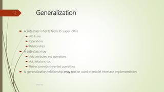
Generalization
Generalization is a taxonomic relationship
between a more general class and a more
specific subclass.
The general class is called a superclass and
the specific class is called a subclass.
The subclass inherits all the attributes and
operations of the superclass.
The subclass may add its own attributes and
operations.
Person
name
age
address
Employee
salary
department
Student
marks
Student
Employee
Generalization
Object Modeling Guidelines
Model real
UML, ER and Dimensional Modelling
UML, ER and Dimensional ModellingStefano Dalla Palma The document discusses several modeling techniques used in software development including the Unified Modeling Language (UML), Entity-Relationship (ER) modeling, and dimensional modeling. It provides an overview of UML diagrams including use case, class, sequence, activity, and other diagrams. It also explains the basic concepts of ER modeling such as entities, attributes, relationships, and cardinalities. Finally, it gives an example of modeling a company database using ER diagrams with entities for departments, projects, employees, and their attributes and relationships.
Uml unified-modeling-language-presented by dileep
Uml unified-modeling-language-presented by dileepmekhap The Unified Modeling Language (UML) is used to specify, visualize, modify, construct and document the artifacts of an object-oriented software-intensive system under development.UML combines techniques from data modeling (entity relationship diagrams), business modeling (work flows), object modeling, and component modeling.
4. UML
4. UMLAshis Kumar Chanda UML is a modeling language used to design and visualize software systems and documents. It includes various diagram types like use case diagrams, which capture system requirements, class diagrams, which show object relationships, and sequence diagrams, which display object interactions over time. Use case diagrams represent interactions between actors and the system through use cases. Class diagrams model the static structure of systems using classes, attributes, operations and relationships. Activity diagrams show the flow of system activities and decisions within a use case scenario.
ASP.NET System design 2
ASP.NET System design 2Sisir Ghosh The document provides information on Unified Modeling Language (UML) and its various diagrams used for modeling software systems. It discusses the background and benefits of object-oriented modeling. It then describes UML as a modeling language comprising various diagram types to capture different views of a system, including structural, behavioral, implementation and user views. Specific diagram types covered include use case diagrams, class diagrams, sequence diagrams, and object diagrams. Examples are provided for each diagram type to illustrate their elements and notation.
Software Testing and UML Lab
Software Testing and UML LabHarsh Kishore Mishra The document describes an admission process management system that aims to automate and computerize the student admission process. It discusses how the current manual system is costly, time-consuming, and difficult to use, while the proposed automated system would be more feasible in terms of cost, time, and effort. The system would use modern technologies like ASP.NET and SQL Server and require only a single operator, reducing costs. It also provides an attractive user interface to make the system easy for operators and users to work with, with fast response times.
Intro Uml
Intro UmlKris der Rose The document provides an overview of the Unified Modeling Language (UML) including its key concepts, terms, and diagram types. It discusses object-orientation, use cases, class diagrams, behavioral modeling using sequence, collaboration, state chart and activity diagrams. It also covers implementation using component and deployment diagrams. The main UML diagram types are use case, class, sequence, state chart, activity, component and deployment diagrams.
Object Oriented Modeling and Design with UML
Object Oriented Modeling and Design with UMLMalek Sumaiya The Complete Reference, Java 2
- Herbert Schild
-TMH
2) Object Oriented Modeling and Design with UML
- Michael Blaha and James Rambaugh
- Pearson
Ad
Recently uploaded (20)

Quantum Computing Quick Research Guide by Arthur Morgan
Quantum Computing Quick Research Guide by Arthur MorganArthur Morgan This is a Quick Research Guide (QRG).
QRGs include the following:
- A brief, high-level overview of the QRG topic.
- A milestone timeline for the QRG topic.
- Links to various free online resource materials to provide a deeper dive into the QRG topic.
- Conclusion and a recommendation for at least two books available in the SJPL system on the QRG topic.
QRGs planned for the series:
- Artificial Intelligence QRG
- Quantum Computing QRG
- Big Data Analytics QRG
- Spacecraft Guidance, Navigation & Control QRG (coming 2026)
- UK Home Computing & The Birth of ARM QRG (coming 2027)
Any questions or comments?
- Please contact Arthur Morgan at [email protected].
100% human made.
DevOpsDays Atlanta 2025 - Building 10x Development Organizations.pptx
DevOpsDays Atlanta 2025 - Building 10x Development Organizations.pptxJustin Reock Building 10x Organizations with Modern Productivity Metrics
10x developers may be a myth, but 10x organizations are very real, as proven by the influential study performed in the 1980s, ‘The Coding War Games.’
Right now, here in early 2025, we seem to be experiencing YAPP (Yet Another Productivity Philosophy), and that philosophy is converging on developer experience. It seems that with every new method we invent for the delivery of products, whether physical or virtual, we reinvent productivity philosophies to go alongside them.
But which of these approaches actually work? DORA? SPACE? DevEx? What should we invest in and create urgency behind today, so that we don’t find ourselves having the same discussion again in a decade?
AI Changes Everything – Talk at Cardiff Metropolitan University, 29th April 2...
AI Changes Everything – Talk at Cardiff Metropolitan University, 29th April 2...Alan Dix Talk at the final event of Data Fusion Dynamics: A Collaborative UK-Saudi Initiative in Cybersecurity and Artificial Intelligence funded by the British Council UK-Saudi Challenge Fund 2024, Cardiff Metropolitan University, 29th April 2025
https://alandix.com/academic/talks/CMet2025-AI-Changes-Everything/
Is AI just another technology, or does it fundamentally change the way we live and think?
Every technology has a direct impact with micro-ethical consequences, some good, some bad. However more profound are the ways in which some technologies reshape the very fabric of society with macro-ethical impacts. The invention of the stirrup revolutionised mounted combat, but as a side effect gave rise to the feudal system, which still shapes politics today. The internal combustion engine offers personal freedom and creates pollution, but has also transformed the nature of urban planning and international trade. When we look at AI the micro-ethical issues, such as bias, are most obvious, but the macro-ethical challenges may be greater.
At a micro-ethical level AI has the potential to deepen social, ethnic and gender bias, issues I have warned about since the early 1990s! It is also being used increasingly on the battlefield. However, it also offers amazing opportunities in health and educations, as the recent Nobel prizes for the developers of AlphaFold illustrate. More radically, the need to encode ethics acts as a mirror to surface essential ethical problems and conflicts.
At the macro-ethical level, by the early 2000s digital technology had already begun to undermine sovereignty (e.g. gambling), market economics (through network effects and emergent monopolies), and the very meaning of money. Modern AI is the child of big data, big computation and ultimately big business, intensifying the inherent tendency of digital technology to concentrate power. AI is already unravelling the fundamentals of the social, political and economic world around us, but this is a world that needs radical reimagining to overcome the global environmental and human challenges that confront us. Our challenge is whether to let the threads fall as they may, or to use them to weave a better future.
Enhancing ICU Intelligence: How Our Functional Testing Enabled a Healthcare I...
Enhancing ICU Intelligence: How Our Functional Testing Enabled a Healthcare I...Impelsys Inc. Impelsys provided a robust testing solution, leveraging a risk-based and requirement-mapped approach to validate ICU Connect and CritiXpert. A well-defined test suite was developed to assess data communication, clinical data collection, transformation, and visualization across integrated devices.
Big Data Analytics Quick Research Guide by Arthur Morgan
Big Data Analytics Quick Research Guide by Arthur MorganArthur Morgan This is a Quick Research Guide (QRG).
QRGs include the following:
- A brief, high-level overview of the QRG topic.
- A milestone timeline for the QRG topic.
- Links to various free online resource materials to provide a deeper dive into the QRG topic.
- Conclusion and a recommendation for at least two books available in the SJPL system on the QRG topic.
QRGs planned for the series:
- Artificial Intelligence QRG
- Quantum Computing QRG
- Big Data Analytics QRG
- Spacecraft Guidance, Navigation & Control QRG (coming 2026)
- UK Home Computing & The Birth of ARM QRG (coming 2027)
Any questions or comments?
- Please contact Arthur Morgan at [email protected].
100% human made.
How analogue intelligence complements AI
How analogue intelligence complements AIPaul Rowe
Artificial Intelligence is providing benefits in many areas of work within the heritage sector, from image analysis, to ideas generation, and new research tools. However, it is more critical than ever for people, with analogue intelligence, to ensure the integrity and ethical use of AI. Including real people can improve the use of AI by identifying potential biases, cross-checking results, refining workflows, and providing contextual relevance to AI-driven results.
News about the impact of AI often paints a rosy picture. In practice, there are many potential pitfalls. This presentation discusses these issues and looks at the role of analogue intelligence and analogue interfaces in providing the best results to our audiences. How do we deal with factually incorrect results? How do we get content generated that better reflects the diversity of our communities? What roles are there for physical, in-person experiences in the digital world?
Cybersecurity Identity and Access Solutions using Azure AD
Cybersecurity Identity and Access Solutions using Azure ADVICTOR MAESTRE RAMIREZ Cybersecurity Identity and Access Solutions using Azure AD
Linux Support for SMARC: How Toradex Empowers Embedded Developers
Linux Support for SMARC: How Toradex Empowers Embedded DevelopersToradex Toradex brings robust Linux support to SMARC (Smart Mobility Architecture), ensuring high performance and long-term reliability for embedded applications. Here’s how:
• Optimized Torizon OS & Yocto Support – Toradex provides Torizon OS, a Debian-based easy-to-use platform, and Yocto BSPs for customized Linux images on SMARC modules.
• Seamless Integration with i.MX 8M Plus and i.MX 95 – Toradex SMARC solutions leverage NXP’s i.MX 8 M Plus and i.MX 95 SoCs, delivering power efficiency and AI-ready performance.
• Secure and Reliable – With Secure Boot, over-the-air (OTA) updates, and LTS kernel support, Toradex ensures industrial-grade security and longevity.
• Containerized Workflows for AI & IoT – Support for Docker, ROS, and real-time Linux enables scalable AI, ML, and IoT applications.
• Strong Ecosystem & Developer Support – Toradex offers comprehensive documentation, developer tools, and dedicated support, accelerating time-to-market.
With Toradex’s Linux support for SMARC, developers get a scalable, secure, and high-performance solution for industrial, medical, and AI-driven applications.
Do you have a specific project or application in mind where you're considering SMARC? We can help with Free Compatibility Check and help you with quick time-to-market
For more information: https://www.toradex.com/computer-on-modules/smarc-arm-family
HCL Nomad Web – Best Practices and Managing Multiuser Environments
HCL Nomad Web – Best Practices and Managing Multiuser Environmentspanagenda Webinar Recording: https://www.panagenda.com/webinars/hcl-nomad-web-best-practices-and-managing-multiuser-environments/
HCL Nomad Web is heralded as the next generation of the HCL Notes client, offering numerous advantages such as eliminating the need for packaging, distribution, and installation. Nomad Web client upgrades will be installed “automatically” in the background. This significantly reduces the administrative footprint compared to traditional HCL Notes clients. However, troubleshooting issues in Nomad Web present unique challenges compared to the Notes client.
Join Christoph and Marc as they demonstrate how to simplify the troubleshooting process in HCL Nomad Web, ensuring a smoother and more efficient user experience.
In this webinar, we will explore effective strategies for diagnosing and resolving common problems in HCL Nomad Web, including
- Accessing the console
- Locating and interpreting log files
- Accessing the data folder within the browser’s cache (using OPFS)
- Understand the difference between single- and multi-user scenarios
- Utilizing Client Clocking
Heap, Types of Heap, Insertion and Deletion
Heap, Types of Heap, Insertion and DeletionJaydeep Kale This pdf will explain what is heap, its type, insertion and deletion in heap and Heap sort
What is Model Context Protocol(MCP) - The new technology for communication bw...
What is Model Context Protocol(MCP) - The new technology for communication bw...Vishnu Singh Chundawat The MCP (Model Context Protocol) is a framework designed to manage context and interaction within complex systems. This SlideShare presentation will provide a detailed overview of the MCP Model, its applications, and how it plays a crucial role in improving communication and decision-making in distributed systems. We will explore the key concepts behind the protocol, including the importance of context, data management, and how this model enhances system adaptability and responsiveness. Ideal for software developers, system architects, and IT professionals, this presentation will offer valuable insights into how the MCP Model can streamline workflows, improve efficiency, and create more intuitive systems for a wide range of use cases.
Splunk Security Update | Public Sector Summit Germany 2025
Splunk Security Update | Public Sector Summit Germany 2025Splunk Splunk Security Update
Sprecher: Marcel Tanuatmadja
Drupalcamp Finland – Measuring Front-end Energy Consumption
Drupalcamp Finland – Measuring Front-end Energy ConsumptionExove How to measure web front-end energy consumption using Firefox Profiler. Presented in DrupalCamp Finland on April 25th, 2025.
Rusty Waters: Elevating Lakehouses Beyond Spark
Rusty Waters: Elevating Lakehouses Beyond Sparkcarlyakerly1 Spark is a powerhouse for large datasets, but when it comes to smaller data workloads, its overhead can sometimes slow things down. What if you could achieve high performance and efficiency without the need for Spark?
At S&P Global Commodity Insights, having a complete view of global energy and commodities markets enables customers to make data-driven decisions with confidence and create long-term, sustainable value. 🌍
Explore delta-rs + CDC and how these open-source innovations power lightweight, high-performance data applications beyond Spark! 🚀
Role of Data Annotation Services in AI-Powered Manufacturing
Role of Data Annotation Services in AI-Powered ManufacturingAndrew Leo From predictive maintenance to robotic automation, AI is driving the future of manufacturing. But without high-quality annotated data, even the smartest models fall short.
Discover how data annotation services are powering accuracy, safety, and efficiency in AI-driven manufacturing systems.
Precision in data labeling = Precision on the production floor.
How Can I use the AI Hype in my Business Context?
How Can I use the AI Hype in my Business Context?Daniel Lehner 𝙄𝙨 𝘼𝙄 𝙟𝙪𝙨𝙩 𝙝𝙮𝙥𝙚? 𝙊𝙧 𝙞𝙨 𝙞𝙩 𝙩𝙝𝙚 𝙜𝙖𝙢𝙚 𝙘𝙝𝙖𝙣𝙜𝙚𝙧 𝙮𝙤𝙪𝙧 𝙗𝙪𝙨𝙞𝙣𝙚𝙨𝙨 𝙣𝙚𝙚𝙙𝙨?
Everyone’s talking about AI but is anyone really using it to create real value?
Most companies want to leverage AI. Few know 𝗵𝗼𝘄.
✅ What exactly should you ask to find real AI opportunities?
✅ Which AI techniques actually fit your business?
✅ Is your data even ready for AI?
If you’re not sure, you’re not alone. This is a condensed version of the slides I presented at a Linkedin webinar for Tecnovy on 28.04.2025.
#StandardsGoals for 2025: Standards & certification roundup - Tech Forum 2025
#StandardsGoals for 2025: Standards & certification roundup - Tech Forum 2025BookNet Canada Book industry standards are evolving rapidly. In the first part of this session, we’ll share an overview of key developments from 2024 and the early months of 2025. Then, BookNet’s resident standards expert, Tom Richardson, and CEO, Lauren Stewart, have a forward-looking conversation about what’s next.
Link to recording, transcript, and accompanying resource: https://bnctechforum.ca/sessions/standardsgoals-for-2025-standards-certification-roundup/
Presented by BookNet Canada on May 6, 2025 with support from the Department of Canadian Heritage.
The Evolution of Meme Coins A New Era for Digital Currency ppt.pdf
The Evolution of Meme Coins A New Era for Digital Currency ppt.pdfAbi john Analyze the growth of meme coins from mere online jokes to potential assets in the digital economy. Explore the community, culture, and utility as they elevate themselves to a new era in cryptocurrency.
tecnologias de las primeras civilizaciones.pdf
tecnologias de las primeras civilizaciones.pdffjgm517 descaripcion detallada del avance de las tecnologias en mesopotamia, egipto, roma y grecia.
What is Model Context Protocol(MCP) - The new technology for communication bw...
What is Model Context Protocol(MCP) - The new technology for communication bw...Vishnu Singh Chundawat
Ad
UML Class Diagram Notation
- 1. TOPIC:UML CLASS DIAGRAM NOTATION 17BS(IT)63 1 Shaheed Benazir Bhutto University Shaheed Benazir Abad Name: Adnan Ejaz Roll No: 17BSIT(063) Present to: ABC……
- 2. What is a Class Diagram? A Class Diagram is a diagram describing the structure of a system • shows the system's • classes • Attributes • operations (or methods), • Relationships among the classes. 17BS(IT)63 2
- 3. Essential Elements of a UML Class Diagram Class Attributes Operations Relationships Associations Generalization Realization 17BS(IT)63 3
- 4. Class Describes a set of objects having similar: – Attributes (status) – Operations (behavior) Class Name Window – Relationships with other classes • Attributes and operations may Attributes size: Size visibility: – have their visibility marked: visibility: boolean Operations display() hide() 17BS(IT)63 4
- 5. Associations An association between two classes indicates that objects at one end of an association “recognize” objects at the other end and may send messages to them. • Example: “An Employee works for a Company” Employee Company 17BS(IT)63 5
- 6. Associations (cont.) StaffMember Student 1..* *instructs instructor Association name Role name Multiplicity Navigable (uni-directional) association Courses pre - requisites 0..3 Reflexive association Role * 17BS(IT)63 6
- 7. Associations (cont.) To clarify its meaning, an association may be named. The name is represented as a label placed midway along the association line. Usually a verb or a verb phrase. A role is an end of an association where it connects to a class. May be named to indicate the role played by the class attached to the end of the association path. Usually a noun or noun phrase 17BS(IT)63 7
- 8. Associations (cont.) Mandatory for reflexive associations Multiplicity the number of objects that participate in the association. Indicates whether or not an association is mandatory. Multiplicity Indicators Exactly one 1 Zero or more (unlimited)* (0..*) One or more 1..* Zero or one (optional association) 0..1 Specified range 2..4 Multiple, disjoint ranges 2, 4..6, 8 17BS(IT)63 8
- 9. Aggregation A special form of association that models a whole-part relationship between an aggregate (the whole) and its parts. – Models a “is a part-part of” relationship. Whole Part Car Door House 1..*2..* 17BS(IT)63 9
- 10. Aggregation (cont.) Aggregation tests: – Is the phrase “part of” used to describe the relationship? A door is “part of” a car Are some operations on the whole automatically applied to its parts? Move the car, move the door. Are some attribute values propagated from the whole to all or some of its parts? The car is blue, therefore the door is blue. Is there an intrinsic asymmetry to the relationship where one class is subordinate to the other? A door is part of a car. A car is not part of a door. 17BS(IT)63 10
- 11. Generalization Indicates that objects of the specialized class (subclass) are substitutable for objects of the generalized class (super-class). – “is kind of” relationship. Shape }abstract{ Circle Super Class Sub Class An abstract class Generalization relationship 17BS(IT)63 11
- 12. Generalization A sub-class inherits from its super-class Attributes Operations Relationships A sub-class may Add attributes and operations Add relationships Refine (override) inherited operations A generalization relationship may not be used to model interface implementation. 17BS(IT)63 12
- 13. Realization A realization relationship indicates that one class implements a behavior specified by another class (an interface or protocol). An interface can be realized by many classes. A class may realize many interfaces. LinkedList <<interface>> List 17BS(IT)63 13