UML Modeling and Profiling Lab - Advanced Software Engineering Course 2014/2015
Download as PPTX, PDF5 likes920 views

The document is a slide presentation on UML modeling and profiling from a software engineering course. It introduces UML and the concepts of metamodeling. It explains that UML is used to specify, visualize, construct and document software system artifacts. The presentation then outlines the typical steps in UML modeling: 1) modeling use cases, 2) modeling system structure with classes and components, and 3) modeling deployment to hardware nodes.


![Step 4, StateMachines
4
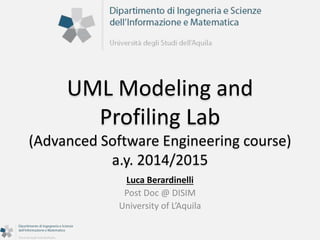
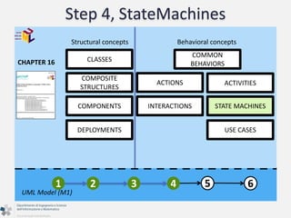
STATE MACHINES
A State models a situation during which some invariant condition
holds. The invariant may represent a static situation such as an
object waiting for some external event to occur. However, it can
also model dynamic conditions such as the process of performing
some behavior (e.g., running, waiting).
Transition
A Transition is a directed relationship between a source State
and a target State. It [...] takes the state machine from one state
configuration to another, representing the complete response
of the state machine to an occurrence of an event of a
particular type.
1 2 3 4 5 6
State
UML Model (M1)](https://image.slidesharecdn.com/umlmodelingprofiling2014-141022095822-conversion-gate01/85/UML-Modeling-and-Profiling-Lab-Advanced-Software-Engineering-Course-2014-2015-40-320.jpg)


![Step 5, Activities
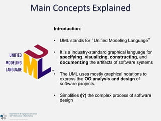
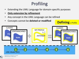
• An activity in Unified Modeling Language (UML) is a major
task that must take place in order to fulfill an operation
contract. Activities can be represented in activity diagrams
• An activity can represent:
o The invocation of an operation.
o A step in a business process.
o An entire business process.
• Activities can be decomposed into sub activities, until at the
bottom we find atomic actions.
1 2 3 4 5 6
UML Model (M1)
[cit. Wikipedia]](https://image.slidesharecdn.com/umlmodelingprofiling2014-141022095822-conversion-gate01/85/UML-Modeling-and-Profiling-Lab-Advanced-Software-Engineering-Course-2014-2015-45-320.jpg)


![Step 6, Interactions
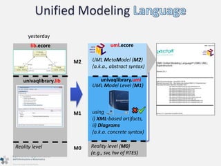
6
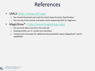
INTERACTIONS
A Lifeline represents an individual participant in the Interaction.
[...]Lifelines represent only one interacting entity.
Lifeline
Message
A Message defines a particular communication between
Lifelines of an Interaction. A communication can be, for
example, raising a signal, invoking an Operation, creating or
destroying an Instance. The Message specifies also the sender
and the receiver. A Message associates normally two executions
- one sending and one receiving.
1 2 3 4 5 6
UML Model (M1)](https://image.slidesharecdn.com/umlmodelingprofiling2014-141022095822-conversion-gate01/85/UML-Modeling-and-Profiling-Lab-Advanced-Software-Engineering-Course-2014-2015-53-320.jpg)


![Profiling
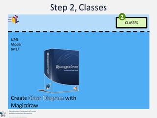
CLASSES
A Class describes a set of objects that share the same specifications
of features, constraints, and semantics. Class is a kind of classifier
whose features are Properties and Operations. Property are
owned by the class. Some of these Properties may represent the
navigable ends of binary Associations.
Class
My Profile For HTML Docs
stereotype
<<HTML>>
The stereotype <<HTML>> is applied to (and only to!) Class
model elements that has to be documented through HTML-based
document [...]
1 2 3 4 5 6
UML Model (M1)
Defining a Profile](https://image.slidesharecdn.com/umlmodelingprofiling2014-141022095822-conversion-gate01/85/UML-Modeling-and-Profiling-Lab-Advanced-Software-Engineering-Course-2014-2015-60-320.jpg)


UML Modeling and Profiling Lab - Advanced Software Engineering Course 2014/2015
- 1. UML Modeling and Profiling Lab (Advanced Software Engineering course) a.y. 2014/2015 Luca Berardinelli Post Doc @ DISIM University of L’Aquila
- 2. Copyright Notice The material in these slides may be freely reproduced and distributed, partially or totally, as far as an explicit reference or acknowledge to the material author is preserved.
- 3. Lecturer
- 4. Note • Next Lesson: SOA, Monday at 11.00 in A.1.6 • Check the website
- 5. Metamodeling, what we did Raise the abstraction level Problem domain Solution domain (sw) Reqs Specs Design Implementation Deployment Runtime MMM MMM MMM MMM MMM Main.java Main.class Main.jar >java Main.jar Main.war MyModel.lib Designer languages(s) <<specified in>> <<creates>> model(s) diagrams ignored! <<read by>> Model Editor, Model Transformations <<creates>> <<specified using>> Eclipse EMF, Eclipse RCP <<read by>> diagrams help! Other Stakeholders (e.g., colleagues)
- 6. Metamodeling, what we did Raise the abstraction level Problem domain Solution domain (sw) Reqs Specs Design Implementation Deployment Runtime MMM MMM MMM MMM MMM Main.java Main.class Main.jar >java Main.jar Main.war MyModel.mylang no diagrams (see Eclipse GMF) Designer <<creates>> <<specified in>> <<read by>> Model Editor, Model Transformations <<creates>> <<specified using>> Eclipse EMF, Eclipse RCP
- 7. UML Modeling: setting the context Raise the abstraction level Problem domain Solution domain (sw) Reqs Specs Design Implementation Deployment Runtime MMM MMM MMM MMM MMM Main.java Main.class Main.jar >java Main.jar Main.war MyModel.uml Designer UML <<specified in>> <<creates>> UML model(s) <<read by>> Model Editor (MagicDraw) <<reuses>> <<read by>> diagrams help! Other Stakeholders (e.g., colleagues)
- 8. UML Profiling: setting the context Raise the abstraction level Problem domain Solution domain (sw) Reqs Specs Design Implementation Deployment Runtime MMM MMM MMM MMM MMM Main.java Main.class Main.jar >java Main.jar Main.war MyModel.uml Designer UML <<specified in>> <<creates>> UML model(s) <<read by>> Model Editor (MagicDraw) <<reuses>> <<created using>> <<read by>> diagrams help! Other Stakeholders (e.g., colleagues) <<extends>> Profile(s) <<annotated with>>
- 9. Main Concepts Explained Introduction: • UML stands for “Unified Modeling Language” • It is a industry-standard graphical language for specifying, visualizing, constructing, and documenting the artifacts of software systems • The UML uses mostly graphical notations to express the OO analysis and design of software projects. • Simplifies (?) the complex process of software design
- 10. UML is not (only) a set of diagrams
- 11. Unified Modeling UML MetaModel (M2) (a.k.a., abstract syntax) UML Model Level (M1) using i) XML-based artifacts, ii) Diagrams (a.k.a. concrete syntax) M2 M1 Reality level Reality level (M0) (e.g., sw, hw of RTES) yesterday M0 lib.ecore univaqlibrary.lib uml.ecore univaqlibrary.uml
- 12. Unified Modeling UML Metamodel (M2) extend by refining PROFILES extend by refining UML Model (M1) Structural concepts Behavioral concepts COMPONENTS Reality level (e.g., sw, hw of RTES) CLASSES COMPOSITE STRUCTURES DEPLOYMENTS COMMON BEHAVIORS ACTIONS ACTIVITIES INTERACTIONS STATE MACHINES USE CASES
- 13. Unified Modeling • How to model a System in UML? Where should I start? UML Model (M1) Reality level (e.g., sw, hw of RTES) Generic Modeling Workflow 1. modeling use cases 2. modeling system structure • software architecture • hardware architecture 3. modeling system behavior • software behavior • hardware behavior UML MetaModel (M2)
- 14. Unified Modeling • How to model a System in UML? Where should I start? UML Model (M1) Another Modeling Workflow 1. modeling use cases 2. modeling system behavior • software behavior • hardware behavior 3. modeling system structure • software architecture • hardware architecture UML MetaModel (M2) Reality (M0)
- 15. Unified Modeling 1 2 3 4 (s) UML Model (M1) (s) for Sw (s) for Sw 5 + MyProfile (s) for Sw (s) for Sw / Hw (s) for Hw 6 UML MetaModel (M2) Reality (M0)
- 16. Unified Modeling extend by refining PROFILES extend by refining UML MetaModel (M2) UML Model (M1) Structural concepts Behavioral concepts CLASSES COMPOSITE STRUCTURES COMPONENTS DEPLOYMENTS COMMON BEHAVIORS 5 ACTIONS ACTIVITIES INTERACTIONS STATE MACHINES USE CASES 2 4 6 3 1 Reality (M0)
- 17. Step 1, Use Cases Structural concepts Behavioral concepts CLASSES COMPOSITE STRUCTURES COMPONENTS DEPLOYMENTS COMMON BEHAVIORS ACTIONS ACTIVITIES INTERACTIONS STATE MACHINES USE CASES CHAPTER 16 1 2 3 4 5 6 UML MetaModel (M2) UML Model (M1)
- 18. Step 1, Use Cases • Identifying the system boundaries, • Identifying inputs/output from/to the external environment • Identifying the main system functionalities and their relationships with external actors and among functionalities (extends, includes) 1 2 3 4 5 6 UML Model (M1)
- 19. Step 1, Use Cases CHAPTER 16 1 2 3 4 5 6 UML Model (M1) USE CASES 1 A UseCase is the specification of a set of actions performed by a system (i.e., the IPS), which yields an observable result that is, typically, of value for one or more actors or other stakeholders of the system. UseCase Actor An Actor models a type of role played by an entity that interacts with the subject (i.e. the IPS) (e.g., by exchanging signals and data), but which is external to the subject (i.e., in the sense that an instance of an actor is not a part of the instance of its corresponding subject). Actors may represent roles played by human users, external hardware, or other subjects.
- 20. Step 1, Use Cases CHAPTER 16 1 2 3 4 5 6 UML Model (M1) USE CASES 1 UseCase Actor
- 21. Step 1, Use Cases UML Model (M1) 1 USE CASES
- 22. Step 1, Use Cases UML Model (M1) 1 USE CASES Create with MagicDraw
- 23. Step 2, Classes Structural concepts Behavioral concepts CLASSES COMPOSITE STRUCTURES COMMON BEHAVIORS 1 2 3 4 5 6 UML Model (M1) COMPONENTS DEPLOYMENTS ACTIONS ACTIVITIES INTERACTIONS STATE MACHINES USE CASES CHAPTER 16
- 24. Step 2, Classes • Identifying the main constituent elements of your system • Determining their relationships o Association o Composition o Generalization • Determining their multiplicities at run time (how many objects?) o 0..1 (optional) o 1 (required) o 0..N (optional, multiple) o 1..N (required, multiple) 1 2 3 4 5 6 UML Model (M1)
- 25. Step 2, Classes CLASSES 2 A Class describes a set of objects that share the same specifications of features, constraints, and semantics. Class is a kind of classifier whose features are Properties and Operations. Property are owned by the class. Some of these Properties may represent the navigable ends of binary Associations. Property A Property is a StructuralFeature. A Property can be an owned attribute or association end. It relates an instance of the class to a value or collection of values of the type of the attribute. ... 1 2 3 4 5 6 Class UML Model (M1)
- 26. Step 2, Classes UML Model (M1) CLASSES 2 Closely related diagrams It allows to display "containement" Class Diagram Composite Structure Diagram
- 27. Step 2, Classes CLASSES 2 1 2 3 4 5 6 UML Model (M1) An InstanceSpecification is a model element that represents an instance in a modeled system. For example, an instance specification of a Class describes an object of that class, while an instance of an Association describes a link Class Property A Slot specifies that an Instance Specification has a value or values for its Property. Instance Specification Slot
- 28. Step 2, Classes UML Model (M1) CLASSES 2 Class -> Car, Wheel InstanceSpecfications: usually all the boxes with underlined names Class Class link link
- 29. Step 2, Classes UML Model (M1) CLASSES 2 Create with Magicdraw
- 30. Step 3, Deployments Structural concepts Behavioral concepts CLASSES COMPOSITE STRUCTURES COMMON BEHAVIORS 1 2 3 4 5 6 UML Model (M1) COMPONENTS DEPLOYMENTS ACTIONS ACTIVITIES INTERACTIONS STATE MACHINES USE CASES CHAPTER 16
- 31. Step 3, Deployments • The Deployments package specifies a set of constructs that can be used to define the execution architecture of systems that represent the assignment of software artifacts to nodes.. • Identifying the main constituent elements (nodes) of a hardware platform, hosting the execution of software elements • Determining their multiplicities of hardware elements o 0..1 (optional) o 1 (required) o 0..N (optional, multiple) o 1..N (required, multiple) 1 2 3 4 5 6 UML Model (M1)
- 32. Step 3, Deployments 3 DEPLOYMENTS A Node is computational resource upon which Artifacts may be deployed for execution. Nodes can be interconnected through Communication Paths to define network structures. Artifact An Artifact is the specification of a physical piece of information that is used or produced by a software development process, or by deployment and operation of a system. Examples of artifacts include model files, source files, scripts, and binary executable files, a table in a database system, a development deliverable, or a word-processing document, a mail message. 1 2 3 4 5 6 Node UML Model (M1)
- 33. Step 3, Deployments 3 DEPLOYMENTS Artifact 1 2 3 4 5 6 Node UML Model (M1)
- 34. Step 3, Deployments UML Model (M1) 3 DEPLOYMENTS
- 35. Step 3, Deployments 3 DEPLOYMENTS Communication 1 2 3 4 5 6 Node Path UML Model (M1) An InstanceSpecification is a model element that represents an instance in a modeled system. For example, an instance specification of a Class describes an object of that class, while an instance of an Association describes a link A Slot specifies that an Instance Specification has a value or values for its Property. Instance Specification Link
- 36. Step 3, Deployments UML Model (M1) 3 DEPLOYMENTS Link
- 37. Step 3, Deployments UML Model (M1) 3 DEPLOYMENTS Create with MagicDraw
- 38. Step 4, StateMachines Structural concepts Behavioral concepts CLASSES COMPOSITE STRUCTURES COMMON BEHAVIORS 1 2 3 4 5 6 UML Model (M1) COMPONENTS DEPLOYMENTS ACTIONS ACTIVITIES INTERACTIONS STATE MACHINES USE CASES CHAPTER 16
- 39. Step 4, StateMachines • The StateMachines unit defines a set of concepts that can be used for modeling discrete behavior through finite state-transition systems. • State machines can be used to specify behavior of various model elements. For example, they can be used to model the behavior of individual entities. 1 2 3 4 5 6 UML Model (M1)
- 40. Step 4, StateMachines 4 STATE MACHINES A State models a situation during which some invariant condition holds. The invariant may represent a static situation such as an object waiting for some external event to occur. However, it can also model dynamic conditions such as the process of performing some behavior (e.g., running, waiting). Transition A Transition is a directed relationship between a source State and a target State. It [...] takes the state machine from one state configuration to another, representing the complete response of the state machine to an occurrence of an event of a particular type. 1 2 3 4 5 6 State UML Model (M1)
- 41. Step 4, StateMachines 4 STATE MACHINES Transition 1 2 3 4 5 6 State UML Model (M1)
- 42. Step 4, StateMachines UML Model (M1) STATE 4 MACHINES SwProcess Signal Event: admitted, interrupt, exit...
- 43. Step 4, StateMachines UML Model (M1) STATE 4 MACHINES Create with MagicDraw
- 44. Step 5, Activities Structural concepts Behavioral concepts CLASSES COMPOSITE STRUCTURES COMMON BEHAVIORS 1 2 3 4 5 6 UML Model (M1) COMPONENTS DEPLOYMENTS ACTIONS ACTIVITIES INTERACTIONS STATE MACHINES USE CASES CHAPTER 16
- 45. Step 5, Activities • An activity in Unified Modeling Language (UML) is a major task that must take place in order to fulfill an operation contract. Activities can be represented in activity diagrams • An activity can represent: o The invocation of an operation. o A step in a business process. o An entire business process. • Activities can be decomposed into sub activities, until at the bottom we find atomic actions. 1 2 3 4 5 6 UML Model (M1) [cit. Wikipedia]
- 46. Step 5, Activities ACTIVITIES 5 An Action is a named element that is the fundamental unit of executable functionality. The execution of an action represents some transformation or processing in the modeled system Control Flow A ControlFlow is an edge that starts an activity node after the previous one is finished. 1 2 3 4 5 6 Action UML Model (M1)
- 47. Step 5, Activities 1 2 3 4 5 6 UML Model (M1) ACTIVITIES 5 Action Control Flow
- 48. Step 5, Activities UML Model (M1) 5 ACTIVITIES control flow object flow pin action
- 49. Step 5, Activities UML Model (M1) 5 ACTIVITIES Activity as Operation Behavior Specification
- 50. Step 5, Activities UML Model (M1) Create with MagicDraw 5 ACTIVITIES
- 51. Step 6, Interactions Structural concepts Behavioral concepts CLASSES COMPOSITE STRUCTURES COMMON BEHAVIORS 1 2 3 4 5 6 UML Model (M1) COMPONENTS DEPLOYMENTS ACTIONS ACTIVITIES INTERACTIONS STATE MACHINES USE CASES CHAPTER 16
- 52. Step 6, Interactions • Interactions can be used for several purposes including o modeling the exchange of messages across different objects o tracking /visualizing the execution of a System in terms of invoked operations 1 2 3 4 5 6 UML Model (M1)
- 53. Step 6, Interactions 6 INTERACTIONS A Lifeline represents an individual participant in the Interaction. [...]Lifelines represent only one interacting entity. Lifeline Message A Message defines a particular communication between Lifelines of an Interaction. A communication can be, for example, raising a signal, invoking an Operation, creating or destroying an Instance. The Message specifies also the sender and the receiver. A Message associates normally two executions - one sending and one receiving. 1 2 3 4 5 6 UML Model (M1)
- 54. Step 6, Interactions 6 INTERACTIONS Lifeline Message 1 2 3 4 5 6 UML Model (M1)
- 55. Step 6, Interactions UML Model (M1) 6 INTERACTIONS C1 C2 +foo(x) C3 C2 +doit(z) ____ ____ ____
- 56. Step 6, Interactions UML Model (M1) 6 INTERACTIONS Create with MagicDraw
- 57. Profiling extends by refining PROFILES extends by refining Structural concepts Behavioral concepts UML Model (M1) CLASSES COMPOSITE STRUCTURES COMPONENTS DEPLOYMENTS COMMON BEHAVIORS 5 ACTIONS ACTIVITIES INTERACTIONS STATE MACHINES USE CASES 2 4 6 3 1 1 2 3 4 5 6
- 58. Why I need a profile Raise the abstraction level Problem domain Solution domain (sw) Reqs Specs Design Implementation Deployment Runtime MMM MMM MMM MMM MMM Main.java Main.class Main.jar >java Main.jar Main.war MyModel.uml Documentation m2m transformation browser MMM docs.html Annotations on models (M1) using stereotypes and their properties are similar to "structured comments" in programming languages. You can add them to enable and remove them without "corrupting" the structure and behavioral specification of a UML model
- 59. CLASSES Profiling • Extending the UML Language for domain-specific purposes • Only extension by refinement • Any concept in the UML Language can be refined • Concepts cannot be deleted or modified Class 1..* Defining a Profile 1 2 3 4 5 6 UML Model (M1) MY PROFILE stereotype STATEMACHINES State CLASSES Class STATEMACHINES State
- 60. Profiling CLASSES A Class describes a set of objects that share the same specifications of features, constraints, and semantics. Class is a kind of classifier whose features are Properties and Operations. Property are owned by the class. Some of these Properties may represent the navigable ends of binary Associations. Class My Profile For HTML Docs stereotype <<HTML>> The stereotype <<HTML>> is applied to (and only to!) Class model elements that has to be documented through HTML-based document [...] 1 2 3 4 5 6 UML Model (M1) Defining a Profile
- 61. Profiling UML Model (M1) Class stereotype <<HTML>> <<HTML>> <<HTML>> <<HTML>> <<HTML>> <<HTML>> <<HTML>> 2 Defining a Profile Applying a Profile
- 62. Profiling UML Model (M1) MyProfile Defining a Profile Applying a Profile 1) Define and 2) Apply a new
- 63. Artifacts from annotated UML Models UML Model (M1) model transformation(s) Analysis Model Code Docs
- 64. References • UML2: http://www.uml.org/ o You should download and read the lastest Superstructure Specification o You can also find tutorials and books online explaining UML for beginners. • MagicDraw® : http://www.magicdraw.com/ o You can find video tutorial on the web site o Existing profiles are in <install.root>/profiles/ o <install.root>/manuals/ for additional documentation about MagicDraw® and its capabilities