


Ad
More Related Content
Similar to UNIT 5 INPUT OUTPUT.pptx computer (20)
Recently uploaded (20)


Ad
UNIT 5 INPUT OUTPUT.pptx computer
- 1. 03/15/2025 1 Ms. Deepshikha Rai Department of MCA Computer Organization and Architecture (BMC 105) Unit - 5 INPUT/OUTPUT Ms. Deepshikha Rai Asst. Prof. IMS Engineering College
- 2. 03/15/2025 Ms. Deepshikha Rai Asst. Prof. IMS Engineering College 2 Introduction to Input-Output Interface Input-Output Interface: The method that is used to transfer information between internal storage and external I/O devices is known as I/O interface A peripheral device is that which provide input and output for the computer, it is also called Input- Output devices. For Example: A keyboard and mouse provide Input to the computer are called input devices while a monitor and printer that provide output to the computer are called output devices. Just like the external hard-drives, there is also availability of some peripheral devices which are able to provide both input and output.
- 3. 03/15/2025 Ms. Deepshikha Rai Asst. Prof. IMS Engineering College 3 Input-Output Interface The nature of peripheral devices is electromagnetic and electro-mechanical. The nature of the CPU is electronic. There is a lot of difference in the mode of operation of both peripheral devices and CPU. There is a special need of the additional hardware to resolve the differences between CPU and peripheral devices to supervise and synchronize all input and output devices.
- 4. 03/15/2025 Ms. Deepshikha Rai Asst. Prof. IMS Engineering College 4 Functions of Input-Output Interface: 1. It is used to synchronize the operating speed of CPU with respect to input-output devices. 2. It selects the input-output device which is appropriate for the interpretation of the input-output device. 3. It is capable of providing signals like control and timing signals. 4. In this data buffering can be possible through data bus. 5. There are various error detectors. 6. It converts serial data into parallel data and vice-versa. 7. It also convert digital data into analog signal and vice-versa.
- 5. 03/15/2025 Ms. Deepshikha Rai Asst. Prof. IMS Engineering College 5 Input Output Ports Ports: The connection point acts as an interface between the computer and external devices like printers, modems, etc There are two types of ports : Internal Port: It connects the system’s motherboard to internal devices like hard disk, CD drive, internal Bluetooth, etc. External Port: It connects the system’s motherboard to external devices like a mouse, printer, USB, etc.
- 6. 03/15/2025 Ms. Deepshikha Rai Asst. Prof. IMS Engineering College 6 Types of Computer Ports There are different types of ports available: 1. Serial port 2. Parallel port 3. USB port 4. PS/2 port 5. VGA port 6. Modem port Sockets Infrared Port Game Port Digital Video Interface(DVI) Port Ethernet Port 7.FireWire Port 8. Sockets 9. Infrared Port 10. Game Port 11. Digital Video Interface(DVI) Port 12. Ethernet Port
- 7. 03/15/2025 Ms. Deepshikha Rai Asst. Prof. IMS Engineering College 7 Input Output Ports
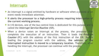
- 8. 03/15/2025 Ms. Deepshikha Rai Asst. Prof. IMS Engineering College 8 Interrupts An interrupt is a signal emitted by hardware or software when a process or an event needs immediate attention. It alerts the processor to a high-priority process requiring interruption of the current working process. In I/O devices, one of the bus control lines is dedicated for this purpose and is called the Interrupt Service Routine (ISR). When a device raises an interrupt at the process, the processor first completes the execution of an instruction. Then it loads the Program Counter (PC) with the address of the first instruction of the ISR. Before loading the program counter with the address, the address of the interrupted instruction is moved to a temporary location. Therefore, after handling the interrupt, the processor can continue with the process.
- 9. 03/15/2025 Ms. Deepshikha Rai Asst. Prof. IMS Engineering College 9 Interrupts While the processor is handling the interrupts, it must inform the device that its request has been recognized to stop sending the interrupt request signal. Also, saving the registers so that the interrupted process can be restored in the future increases the delay between the time an interrupt is received and the start of the execution of the ISR. This is called Interrupt Latency.
- 10. 03/15/2025 Ms. Deepshikha Rai Asst. Prof. IMS Engineering College 10 A single computer can perform only one computer instruction at a time. But, because it can be interrupted, it can manage how programs or sets of instructions will be performed. This is known as multitasking. It allows the user to do many different things simultaneously, and the computer turns to manage the programs that the user starts. Of course, the computer operates at speeds that make it seem like all user tasks are being performed simultaneously.
- 11. 03/15/2025 Ms. Deepshikha Rai Asst. Prof. IMS Engineering College 11 Types of Interrupt Interrupt signals may be issued in response to hardware or software events. These are classified as hardware interrupts or software interrupts, respectively.
- 12. 03/15/2025 Ms. Deepshikha Rai Asst. Prof. IMS Engineering College 12 1. Hardware Interrupts A hardware interrupt is a condition related to the state of the hardware that may be signaled by an external hardware device, e.g., an interrupt request (IRQ) line on a PC, or detected by devices embedded in processor logic to communicate that the device needs attention from the operating system. For example, pressing a keyboard key or moving a mouse triggers hardware interrupts that cause the processor to read the keystroke or mouse position.
- 13. 03/15/2025 Ms. Deepshikha Rai Asst. Prof. IMS Engineering College 13 2. Software Interrupts The processor requests a software interrupt upon executing particular instructions or when certain conditions are met. Every software interrupt signal is associated with a particular interrupt handler. A software interrupt may be intentionally caused by executing a special instruction that invokes an interrupt when executed by design. Such instructions function similarly to subroutine calls and are used for various purposes, such as requesting operating system services and interacting with device drivers.
- 14. 03/15/2025 Ms. Deepshikha Rai Asst. Prof. IMS Engineering College 14 Handling Multiple Devices
- 15. 03/15/2025 Ms. Deepshikha Rai Asst. Prof. IMS Engineering College 15 1. Polling Polling is a method of controlling the access to a transmission medium which is shared by a number of stations. In polling, the first device encountered with the IRQ bit set is to be serviced first, and appropriate ISR is called to service the same. It is easy to implement, but a lot of time is wasted by interrogating the IRQ bit of all devices. 2. Vectored Interrupts In vectored interrupts, a device requesting an interrupt identifies itself directly by sending a special code to the processor over the bus. This enables the processor to identify the device that generated the interrupt. The special code can be the starting address of the ISR or where the ISR is located in memory and is called the interrupt vector.
- 16. 03/15/2025 Ms. Deepshikha Rai Asst. Prof. IMS Engineering College 16 3. Interrupt Nesting In this method, the I/O device is organized in a priority structure. Therefore, an interrupt request from a higher priority device is recognized, whereas a lower priority device is not. The processor accepts interrupts only from devices/processes having priority more than it. Processors priority is encoded in a few bits of PS (Process Status register), and it can be changed by program instructions that write into the PS. The processor is in supervised mode only while executing OS routines, and it switches to user mode before executing application programs.
- 17. 03/15/2025 Ms. Deepshikha Rai Asst. Prof. IMS Engineering College 17 Mode of data Transfer: The binary information that is received from an external device is usually stored in the memory unit. The information that is transferred from the CPU to the external device is originated from the memory unit. CPU merely processes the information but the source and target is always the memory unit. Data transfer between CPU and the I/O devices may be done in different modes.
- 18. 03/15/2025 Ms. Deepshikha Rai Asst. Prof. IMS Engineering College 18 Data transfer to and from the peripherals may be done in any of the three possible ways 1. Programmed I/O. 2. Interrupt- initiated I/O. 3. Direct memory access( DMA).
- 19. 03/15/2025 Ms. Deepshikha Rai Asst. Prof. IMS Engineering College 19 1. Programmed I/O: It is due to the result of the I/O instructions that are written in the computer program. Each data item transfer is initiated by an instruction in the program. Usually the transfer is from a CPU register and memory. In this case it requires constant monitoring by the CPU of the peripheral devices.Example of Programmed I/O: In this case, the I/O device does not have direct access to the memory unit. A transfer from I/O device to memory requires the execution of several instructions by the CPU
- 20. 03/15/2025 Ms. Deepshikha Rai Asst. Prof. IMS Engineering College 20 2. Interrupt- initiated I/O: Since in the above case we saw the CPU is kept busy unnecessarily. This situation can very well be avoided by using an interrupt driven method for data transfer. By using interrupt facility and special commands to inform the interface to issue an interrupt request signal whenever data is available from any device. In the meantime the CPU can proceed for any other program execution. Note: Both the methods programmed I/O and Interrupt-driven I/O require the active intervention of the processor to transfer data between memory and the I/O module
- 21. 03/15/2025 Ms. Deepshikha Rai Asst. Prof. IMS Engineering College 21 Direct Memory Access(DMA) DMA is a method that allows an I/O devices directly to or from the main memory bypassing the CPU to speed up memory operation. The process is managed by Chip know as a DMA controller(DMAC). DMA Controller is a hardware device that allows I/O devices to directly access memory with less participation of the processor. DMA controller needs the same old circuits of an interface to communicate with the CPU and Input/Output devices. It gets 4 parameters. 1) Source Address 2) Destination Address 3) Byte Count 4) Read/Write
- 22. 03/15/2025 Ms. Deepshikha Rai Asst. Prof. IMS Engineering College 22 Block diagram of DMA
- 23. 03/15/2025 Ms. Deepshikha Rai Asst. Prof. IMS Engineering College 23 DMA: Fig-1 below shows the block diagram of the DMA controller. The unit communicates with the CPU through data bus and control lines. Through the use of the address bus and allowing the DMA and RS register to select inputs, the register within the DMA is chosen by the CPU. RD and WR are two-way inputs. When BG (bus grant) input is 0, the CPU can communicate with DMA registers. When BG (bus grant) input is 1, the CPU has relinquished the buses and DMA can communicate directly with the memory. The DMA controller has three registers as follows. Address register – It contains the address to specify the desired location in memory. Word count register – It contains the number of words to be transferred. Control register – It specifies the transfer mode.
- 24. 03/15/2025 Ms. Deepshikha Rai Asst. Prof. IMS Engineering College 24 DMA: Explanation : The CPU initializes the DMA by sending the given information through the data bus. The starting address of the memory block where the data is available (to read) or where data are to be stored (to write). It also sends word count which is the number of words in the memory block to be read or write. Control to define the mode of transfer such as read or write. A control to begin the DMA transfer.
- 25. 03/15/2025 Ms. Deepshikha Rai Asst. Prof. IMS Engineering College 25 DMA: Bus Request : It is used by the DMA controller to request the CPU to relinquish the control of the buses. Bus Grant : It is activated by the CPU to Inform the external DMA controller that the buses are in high impedance state and the requesting DMA can take control of the buses. Once the DMA has taken the control of the buses it transfers the data. This transfer can take place in many ways.
- 26. 03/15/2025 Ms. Deepshikha Rai Asst. Prof. IMS Engineering College 26 Serial Communication Serial communication is the process of sequentially transferring the information/bits on the same channel. Due to this, the cost of wire will be reduced, but it slows the transmission speed. Generally, communication can be described as the process of interchanging information between individuals in the form of audio, video, verbal words, and written documents. In serial communication, binary pulses are used to show the data. Binary contains the two numbers 0 and 1. 0 is used to show the LOW or 0 Volts, and 1 is used to show the HIGH or 5 Volts. The serial communication can either be asynchronous or synchronous.
- 27. 03/15/2025 Ms. Deepshikha Rai Asst. Prof. IMS Engineering College 27 1. Synchronous Communication In synchronous communication, the frames or data will be constructed with the help of combining the groups of bits. That frames will be continuously sent in time with a master clock. It uses a synchronized clock frequency to operate the data of sender or receiver. In synchronous communication, there is no need to use the gaps, start bits and stop bits.
- 28. 03/15/2025 Ms. Deepshikha Rai Asst. Prof. IMS Engineering College 28 2. Asynchronous Communication In asynchronous communication, the groups of bits will be treated as an independent unit, and these data bits will be sent at any point in time. In order to make synchronization between sender and receiver, the stop bits and start bits are used between the data bytes. These bits are useful to ensure that the data is correctly sent. The time taken by data bits of sender and receiver is not constant, and the time between transmissions will be provided by the gaps.
- 29. 03/15/2025 Ms. Deepshikha Rai Asst. Prof. IMS Engineering College 29 Serial Communication On the basis of the data transfer rate and the type of transmission mode, serial communication will take many forms. The transmission mode can be classified into 1. simplex 2. half-duplex 3. full-duplex Each transmission mode contains the source, also known as sender or transmitter, and destination, also known as the receiver.
- 30. 03/15/2025 Ms. Deepshikha Rai Asst. Prof. IMS Engineering College 30 1. Simplex In the simplex method, the data transmission can be performed only in one direction. At a time, only one client (either sender or receiver) can be active. Example 1: Printers and computers are one more example of the simplex. Computers always send data to the printers, but printers are not able to send the data to the computers
- 31. 03/15/2025 Ms. Deepshikha Rai Asst. Prof. IMS Engineering College 31 2. Half Duplex In the half-duplex, the sender and receiver can communicate in both directions, but not at the same time. Example: Walkie-talkie is also a classic example of half-duplex.
- 32. 03/15/2025 Ms. Deepshikha Rai Asst. Prof. IMS Engineering College 32 3. Full Duplex In the full-duplex, the sender and the receiver are able to send and receive at the same time. The communication mode of full- duplex is widely used in the world. Example: Audio calling or Video calling is also an example of full-duplex. Telephone Network is a good example of full-duplex mode
- 33. 03/15/2025 Ms. Deepshikha Rai Asst. Prof. IMS Engineering College 33 Parallel communication Parallel communication is used to transmit a huge amount of data signals simultaneously on the different channels within the same radio path or cable at a time. It is used to comprise a huge amount of wired channels in parallel. In parallel communication, the data transfer between sender and receiver is done with the help of multiple channels. The data bus in the parallel devices is wider as compared to the serial devices.
- 34. 03/15/2025 Ms. Deepshikha Rai Asst. Prof. IMS Engineering College 34 Thank You