The document provides guidance on developing use case models for a system. It defines key concepts like actors, use cases, include and extend relationships. It explains that use cases describe interactions between actors and the system to achieve goals. The document also provides examples of use case diagrams and descriptions to illustrate how to identify actors and use cases, and describe typical and alternative flows and exceptions. It emphasizes that use cases specify expected behavior from the user's perspective without detailing implementation.
The document discusses use case modeling and UML diagrams. It provides an overview of commonly used UML diagrams such as use case diagrams, activity diagrams, class diagrams, sequence diagrams, and collaboration diagrams. It then describes use cases, use case diagrams, and relationships between use cases including include, extend, and generalize relationships.
This document discusses use case modeling and analysis. It provides an overview of use cases, actors, relationships between use cases, and how to develop a use case model. Key steps include identifying actors and use cases, creating a use case diagram, describing use cases, and prioritizing use cases. The document uses examples of an ATM system and hotel information system to illustrate use case concepts.
The document provides an overview of elements that make up an analysis model, including:
- Use case text, diagrams, activity diagrams, swim lane diagrams, and other modeling techniques.
- The overall objectives of the analysis model are to describe customer requirements, establish a basis for software design, and define requirements that can be validated.
- Scenario-based modeling represents the system from the user's perspective using use case text and diagrams. Elements of use cases and examples of use case diagrams are also described.
This document provides information on object oriented analysis and use case modeling. It discusses identifying objects and their relationships, defining object operations and attributes, and modeling system functionality through use cases. Use cases describe interactions between actors and the system, including typical workflows, alternative scenarios, and pre- and post-conditions. Use case diagrams visually represent the relationships between actors and use cases.
The document discusses use case modeling. It defines use cases as narrative descriptions of domain processes in a structured prose format. It describes key concepts like actors, scenarios, and the relationships between use cases such as include and extend. It provides guidelines for writing use cases, including identifying the system boundary, primary actors, and their goals to derive use cases. It also describes different styles and levels of detail for writing use cases.
The document discusses different approaches to requirements analysis and documentation. It covers defining requirements at a high level through use case diagrams and descriptions before detailing them in specific steps and rules. Both functional and non-functional requirements are important to define the system's behaviors and attributes. The level of documentation needs to balance the needs of different stakeholders while not exceeding what is necessary. The methodology used can influence how and when requirements and documentation are produced.
This document provides an introduction to use case diagrams. It defines a use case as a typical interaction between a user and a system. Use cases capture the functional requirements and how the system benefits users. A use case diagram visually documents user goals and system functionality using actors, use cases, and relationships between use cases. Actors represent people or external systems that interact with the system. Relationships like includes, extends, and generalization define how use cases interact and specialize other use cases. The document provides examples and exercises for creating use case diagrams.
The document discusses use case modeling and provides information on key concepts:
- A use case describes interactions between a system and external users (actors) to achieve a goal. It specifies system behavior but not implementation.
- Key components of use case modeling include actors, use cases, relationships between use cases like inclusion and extension, and use case descriptions.
- Use cases capture functional requirements while use case descriptions elaborate different scenarios through structured text or pseudocode. Organizing use cases into packages supports generalization and specialization.
Requirements engineering emphasizes using systematic techniques to ensure requirements are complete, consistent, and relevant. It encompasses seven tasks: inception, elicitation, elaboration, negotiation, specification, validation, and management. Requirements are statements of what the system must do, how it must behave, and its properties. Requirements engineering produces work products like use cases, class diagrams, and state diagrams to model system behavior and structure. Stakeholder negotiation and validation are important to agree on realistic requirements.
Welcome to my series of articles on Unified Modeling Language. This is "Session 2 – Use Case UML" of the series. I have covered Use Case Scenario, Use Case Narrative and Use Case Model in this session.
Please view my other documents where I have covered each UML diagram with examples
Workshop on Basics of Software Engineering (DFD, UML and Project Culture)Dr Sukhpal Singh Gill
Three days workshop on Basics of Software Engineering at Thapar University, Patiala on 7th-9th, 2013. Workshop on Basics of Software Engineering (DFD, UML and Project Culture)
The document discusses the key activities in requirements engineering including inception, elicitation, analysis modeling, negotiation and validation. It describes techniques used in each stage such as use cases, class and state diagrams to model requirements. Quality function deployment and patterns are also discussed as tools to help define and organize requirements.
In this lesson, you will develop a system using Use Cases.
You will:
Justify the need for a Use Case diagram
Identify and describe the essential elements in a UML Use Case diagram
Identifying the Actors in a System.
Identifying Use Cases in a System
Create a Use Case Diagram that shows the Use Cases in your system.
Recognize and document use case dependencies using UML notation for extends,includes, and generalization
Software System Engineering - Chapter 9Fadhil Ismail
This document discusses use case diagrams and their purpose, notation, and how to create them. Use case diagrams document system functionality from the user's perspective and show interactions between users and the system. They include actors, use cases, and relationships between use cases. Use case descriptions provide further details about specific scenarios. Prototyping can be used alongside use case modeling to help elicit requirements and test system architectures.
The document discusses data flow diagrams (DFDs) and use cases for modeling system requirements. It provides details on how DFDs can be used to model the flow of data through a system using processes, data stores, external entities, and data flows. The document also explains how use cases specify system functionality through interactions between actors and the system. Examples of a DFD and use cases for an online auction system are provided.
Use Case Modeling in Software Development: A Survey and TaxonomyEswar Publications
Identifying use cases is one of the most important steps in the software requirement analysis. This paper makes a literature review over use cases and then presents six taxonomies for them. The first taxonomy is based on the level of functionality of a system in a domain. The second taxonomy is based on primacy of functionality and the third one relies on essentialness of functionality of the system. The fourth taxonomy is concerned with supporting of functionality. The fifth taxonomy is based on the boundary of functionality and the sixth one is related to generalization/specialization relation. Then the use cases are evaluated in a case study in a control command police system. Several guidelines are recommended for developing use cases and their refinement, based on some
practical experience obtained from the evaluation.
This chapter discusses identifying and modeling functional requirements through use cases and user stories. It describes two techniques for identifying use cases: the user goal technique which identifies user goals and tasks, and the event decomposition technique which identifies system responses to different event types. The chapter also covers modeling use cases with descriptions, diagrams, and relationships to define the system functions and actors.
The document provides an overview of a 7-step process for building an information system. The 7 steps are: 1) Identify and list stakeholders, 2) Identify and list actors, 3) Identify and list use cases, 4) Identify and list scenarios, 5) Identify and list steps, 6) Identify and list classes/objects, and 7) Manage work products. It describes each step in the process, including defining stakeholders, actors, use cases, scenarios, and mapping analysis to design. The process emphasizes discovery, iteration, and developing a shared understanding between stakeholders.
1. Defining the system involves developing standard templates, creating a vision document to communicate the product vision, and developing a use case model to define system functionality and stakeholders.
2. A vision document communicates the product's intent, benefits, features and goals to stakeholders. It establishes scope and priorities and records future ideas.
3. A use case model defines the system functions through use cases and actors. It provides a common understanding between developers and customers.
JDBC.ppt database connectivity in java pptkavitamittal18
The document introduces JDBC (Java Database Connectivity) API which allows Java programs to connect to databases. It discusses the four general types of JDBC drivers, focusing on Type 4 or pure Java drivers. Pure Java drivers convert JDBC calls to direct network calls using vendor protocols. The document also outlines the typical JDBC programming procedure of loading a driver, obtaining a connection, executing statements, using result sets, and closing the connection. It provides examples of creating tables and inserting data using JDBC statements.
This document discusses different data types and type systems in programming languages. It covers:
1) Four approaches to defining data types - collection of values, internal structure, equivalence classes, and collections of operations. Most languages combine a structural and abstraction approach.
2) The purposes of types, including providing context and type checking to prevent meaningless operations. Strong and static typing are discussed.
3) Examples of type systems in different languages like Pascal, Java, C, and Python. Common type categories like discrete, scalar, composite, and pointers are also outlined.
4) Concepts related to type checking including equivalence, compatibility, inference, casting, coercion, records, variants, and arrays. Memory layout
09slide.ppt oops classes and objects conceptkavitamittal18
This document discusses object-oriented programming concepts in Java, including classes, objects, and the relationships between them. It introduces the Circle class as an example, explaining that a class acts as a template for objects and defines their data fields and methods. It also discusses how to define classes, create objects from classes using constructors, and access objects' members via reference variables. Key concepts covered include objects having state represented by data fields and behavior defined through methods.
480 GPS Tech mobile computing presentationkavitamittal18
This document provides an overview of the Global Positioning System (GPS) including how it works, sources of error, error correction techniques, applications, and the NMEA standard. GPS uses a constellation of over 24 satellites that orbit 11,000 miles above the Earth and transmit precise time signals. A GPS receiver triangulates its position by precisely timing the signals from at least four satellites. Sources of error include atmospheric effects and issues with satellite orbits. Error correction techniques like DGPS and WAAS can improve accuracy by using reference stations. GPS is used widely in navigation, mapping, and other civilian and military applications.
The document provides an overview of the GSM architecture, which is divided into three main subsystems:
1. The Base Station Subsystem (BSS) which includes the Base Transceiver Station (BTS) and Base Station Controller (BSC).
2. The Network Switching Subsystem (NSS) which includes the Mobile Switching Center (MSC), Home Location Register (HLR), Visitor Location Register (VLR), and Authentication Center (AUC).
3. The Operations and Support Subsystem (OSS) which handles maintenance of the network.
The Mobile Station (MS) consists of the Mobile Equipment (ME) and the Subscriber Identity Module (SIM) card. The SIM card provides
The document outlines an algorithmic foundations of ad hoc networks tutorial, including:
1) An introduction and thanks to the organizers.
2) An agenda covering topics like routing, medium access control, power control, and sensor network protocols.
3) A discussion of medium access control protocols for wireless networks like CSMA, Aloha, Ethernet, and IEEE 802.11, focusing on techniques for avoiding collisions in distributed environments.
Elections in India allow citizens to choose their representatives in a democratic manner. They are held regularly at national and state/local levels to elect members of parliament and legislative assemblies. Key aspects include universal adult suffrage, multiple political parties to choose from, and an independent Election Commission to conduct free and fair polls. While Indian elections are largely accepted as democratic, some challenges remain, such as the influence of money and muscle power, political dynasties, and lack of policy differences between parties.
The document discusses variables, expressions, and arithmetic operators in Java. It defines variables as locations in memory that store values, and expressions as combinations of constants, operators, variables, and parentheses used to calculate values. It also covers variable naming rules, arithmetic operators like addition and multiplication, and the use of parentheses to specify order of operations. Examples of Java code demonstrating arithmetic operations on variables are provided.
This document discusses input and output devices in chapter 4 of the 15th edition of the textbook "Understanding Computers: Today and Tomorrow". It covers keyboards, pointing devices, scanners, readers, digital cameras, audio input, display devices, and printers. The chapter aims to explain the purpose and functions of these common hardware devices used for data input, capture, and output.
Sorting Order and Stability in Sorting.
Concept of Internal and External Sorting.
Bubble Sort,
Insertion Sort,
Selection Sort,
Quick Sort and
Merge Sort,
Radix Sort, and
Shell Sort,
External Sorting, Time complexity analysis of Sorting Algorithms.
☁️ GDG Cloud Munich: Build With AI Workshop - Introduction to Vertex AI! ☁️
Join us for an exciting #BuildWithAi workshop on the 28th of April, 2025 at the Google Office in Munich!
Dive into the world of AI with our "Introduction to Vertex AI" session, presented by Google Cloud expert Randy Gupta.
its all about Artificial Intelligence(Ai) and Machine Learning and not on advanced level you can study before the exam or can check for some information on Ai for project
Concept of Problem Solving, Introduction to Algorithms, Characteristics of Algorithms, Introduction to Data Structure, Data Structure Classification (Linear and Non-linear, Static and Dynamic, Persistent and Ephemeral data structures), Time complexity and Space complexity, Asymptotic Notation - The Big-O, Omega and Theta notation, Algorithmic upper bounds, lower bounds, Best, Worst and Average case analysis of an Algorithm, Abstract Data Types (ADT)
Value Stream Mapping Worskshops for Intelligent Continuous SecurityMarc Hornbeek
This presentation provides detailed guidance and tools for conducting Current State and Future State Value Stream Mapping workshops for Intelligent Continuous Security.
Fluid mechanics is the branch of physics concerned with the mechanics of fluids (liquids, gases, and plasmas) and the forces on them. Originally applied to water (hydromechanics), it found applications in a wide range of disciplines, including mechanical, aerospace, civil, chemical, and biomedical engineering, as well as geophysics, oceanography, meteorology, astrophysics, and biology.
It can be divided into fluid statics, the study of various fluids at rest, and fluid dynamics.
Fluid statics, also known as hydrostatics, is the study of fluids at rest, specifically when there's no relative motion between fluid particles. It focuses on the conditions under which fluids are in stable equilibrium and doesn't involve fluid motion.
Fluid kinematics is the branch of fluid mechanics that focuses on describing and analyzing the motion of fluids, such as liquids and gases, without considering the forces that cause the motion. It deals with the geometrical and temporal aspects of fluid flow, including velocity and acceleration. Fluid dynamics, on the other hand, considers the forces acting on the fluid.
Fluid dynamics is the study of the effect of forces on fluid motion. It is a branch of continuum mechanics, a subject which models matter without using the information that it is made out of atoms; that is, it models matter from a macroscopic viewpoint rather than from microscopic.
Fluid mechanics, especially fluid dynamics, is an active field of research, typically mathematically complex. Many problems are partly or wholly unsolved and are best addressed by numerical methods, typically using computers. A modern discipline, called computational fluid dynamics (CFD), is devoted to this approach. Particle image velocimetry, an experimental method for visualizing and analyzing fluid flow, also takes advantage of the highly visual nature of fluid flow.
Fundamentally, every fluid mechanical system is assumed to obey the basic laws :
Conservation of mass
Conservation of energy
Conservation of momentum
The continuum assumption
For example, the assumption that mass is conserved means that for any fixed control volume (for example, a spherical volume)—enclosed by a control surface—the rate of change of the mass contained in that volume is equal to the rate at which mass is passing through the surface from outside to inside, minus the rate at which mass is passing from inside to outside. This can be expressed as an equation in integral form over the control volume.
The continuum assumption is an idealization of continuum mechanics under which fluids can be treated as continuous, even though, on a microscopic scale, they are composed of molecules. Under the continuum assumption, macroscopic (observed/measurable) properties such as density, pressure, temperature, and bulk velocity are taken to be well-defined at "infinitesimal" volume elements—small in comparison to the characteristic length scale of the system, but large in comparison to molecular length scale
The Fluke 925 is a vane anemometer, a handheld device designed to measure wind speed, air flow (volume), and temperature. It features a separate sensor and display unit, allowing greater flexibility and ease of use in tight or hard-to-reach spaces. The Fluke 925 is particularly suitable for HVAC (heating, ventilation, and air conditioning) maintenance in both residential and commercial buildings, offering a durable and cost-effective solution for routine airflow diagnostics.
3. 3
Use Case Relationships
Domain Model
Use Case Model
Interaction Diagrams
Design
Requirements
Business Model
Objects, attributes, associations
VISION
GLOSSARY
SUPPLEMENTARY
SPECIFICATION
4. 4
Use Cases are not Diagrams
Use Cases may have a diagram associated
with them, and a use case diagram is an
easy way for an analyst to discuss a
process with a subject matter expert (SME).
But use cases are primarily text. The text is
important. The diagram is optional.
5. 5
Emphasize Goals
Investigating goals rather than tasks and
procedures improves information gathering
by focusing on the essence of requirements
—the intent behind them.
Seeing requirements as identifying tasks to
be done has a strong bias toward
reproducing the existing system, even when
it is being replaced because it is seriously
defective.
6. 6
Why Use Cases?
Simple and familiar storytelling makes it
easier, especially for customers, to
contribute and review goals.
Use cases keep it simple (KISS)
They emphasize goals and the user
perspective.
New use case writers tend to take them too
seriously.
7. 7
Actors or Use Case First?
Because you have to understand each part of
Use Cases, the parts are presented separately.
But those who create use cases switch back and
forth. The text describes use cases substantially
before paying attention to actors. Typically, both
actors and use cases are identified early and
then examined to see if more use cases can be
found from the actors, or more actors found by
examining the use cases.
8. 8
Identify Use Cases
Capture the specific ways of using the
system as dialogues between an actor
and the system.
Use cases are used to
Capture system requirements
Communicate with end users and Subject
Matter Experts
Test the system
9. 9
Specifying Use Cases
Create a written document for each Use Case
Clearly define intent of the Use Case
Define Main Success Scenario (Happy Path)
Define any alternate action paths
Use format of Stimulus: Response
Each specification must be testable
Write from actor’s perspective, in actor’s
vocabulary
10. 10
www.usecases.org Template
Name
Primary Actor
Scope
Level
Stakeholders and
Interests
Minimal Guarantee
Success Guarantee
Main Success Scenario
Extensions
This is the basic format used
in the text and in Alistair
Cockburn’s Writing Effective
Use Cases (Addison Wesley,
2000, ISBN 0201702258).
I prefer to modify it slightly to
use the actor actions and
system response in tabular
form. Larman calls this the
Two-Column Variation.
11. 11
Optional Items
You can add some of the following items
Trigger (after Success Guarantee)
(at end:)
Special requirements
Technology and Data Variations
Frequency of Occurrence
Open Issues
13. 13
Elements in the Preface
Only put items that are important to
understand before reading the Main
Success Scenario. These might include:
Name (Always needed for identification)
Primary Actor
Stakeholders and Interests List
Preconditions
Success Conditions (Post Conditions)
14. 14
Naming Use Cases
Must be a complete process from the
viewpoint of the end user.
Usually in verb-object form, like Buy Pizza
Use enough detail to make it specific
Use active voice, not passive
From viewpoint of the actor, not the
system
15. 15
Hint
Appropriate use case names are very important.
Because they are selected early, they tend to set
the direction for the entire project.
Most common errors in use case diagrams are
poor names, showing procedures instead of
complete user processes, and not including the
boundary and system name.
Rational Rose does not show the boundary and
name, so assignments turned in using that tool do
not have to have them. Rational Rose is preferred
for assignments.
16. 16
Golden Rule of Use-Case
Names
Each use case should have a name that
indicates what value (or goal) is achieved by
the actor's interaction with the system
Here are some good questions to help you
adhere to this rule:
Why would the actor initiate this interaction
with the system?
What goal does the actor have in mind when
undertaking these actions?
What value is achieved and for which actor?
From Dr. Use Case (Leslee Probasco) in the Rational Edge, March, 2001
17. 17
Use Case Name Examples
Excellent - Purchase Concert Ticket
Very Good - Purchase Concert Tickets
Good - Purchase Ticket (insufficient detail)
Fair - Ticket Purchase (passive)
Poor - Ticket Order (system view, not user)
Unacceptable - Pay for Ticket (procedure,
not process)
18. 18
CRUD
Examples of bad use case names with the
acronym CRUD. (All are procedural and
reveal nothing about the actor’s
intentions.)
C - actor Creates data
R - actor Retrieves data
U - actor Updates data
D - actor Deletes data
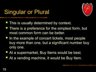
19. 19
Singular or Plural
This is usually determined by context.
There is a preference for the simplest form, but
most common form can be better.
In the example of concert tickets, most people
buy more than one, but a significant number buy
only one.
At a supermarket, Buy Items would be best.
At a vending machine, it would be Buy Item.
20. 20
Identify Actors
We cannot understand a system until we
know who will use it
Direct users
Users responsible to operate and maintain it
External systems used by the system
External systems that interact with the system
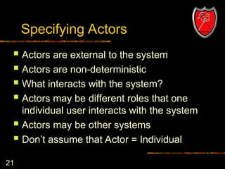
21. 21
Specifying Actors
Actors are external to the system
Actors are non-deterministic
What interacts with the system?
Actors may be different roles that one
individual user interacts with the system
Actors may be other systems
Don’t assume that Actor = Individual
22. 22
Types of Actors
Primary Actor
Has goals to be fulfilled by system
Supporting Actor
Provides service to the system
Offstage Actor
Interested in the behavior, but no contribution
In diagrams, Primary actors go on the left and
others on the right.
23. 23
Define Actors
Actors should not be analyzed or described in detail
unless the application domain demands it.
Template for definition:
Name
Definition
Example for an ATM application:
Customer: Owner of an account who manages account by
depositing and withdrawing funds
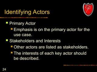
24. 24
Identifying Actors
Primary Actor
Emphasis is on the primary actor for the
use case.
Stakeholders and Interests
Other actors are listed as stakeholders.
The interests of each key actor should
be described.
25. 25
Working with Use Cases
Determine the actors that will interact with
the system
Examine the actors and document their
needs
For each separate need, create a use
case
During Analysis, extend use cases with
interaction diagrams
26. 26
Preconditions
Anything that must always be true before
beginning a scenario is a precondition.
Preconditions are assumed to be true, not
tested within the Use Case itself.
Ignore obvious preconditions such as the
power being turned on. Only document
items necessary to understand the Use
Case.
27. 27
Success Guarantees
Success Guarantees (or Postconditions)
state what must be true if the Use Case is
completed successfully. This may include
the main success scenario and some
alternative paths. For example, if the happy
path is a cash sale, a credit sale might also
be regarded a success.
Stakeholders should agree on the guarantee.
28. 28
Scenarios
The Main Success Scenario, or “happy
path” is the expected primary use of the
system, without problems or exceptions.
Alternative Scenarios or Extensions are
used to document other common paths
through the system and error handling or
exceptions.
29. 29
Documenting the Happy Path
The Success Scenario (or basic course) gives the best
understanding of the use case
Each step contains the activities and inputs of the actor and
the system response
If there are three or more items, create a list
Label steps for configuration management and requirements
traceability
Use present tense and active voice
Remember that User Interface designers will use this
specification
Note: Do not use the term “happy path” in formal documents.
30. 30
Extensions (Alternative Flows)
Extensions or Alternative Flow Use Cases
allow the specification of
Different ways of handling transactions
Error processes
Sections are convenient way to handle
alternative courses of action
Sections are a segment of a use case
executed out of sequence
31. 31
Two Parts for Extensions
Condition
Describe the reason for the alternative
flow as a condition that the user can
detect
Handling
Describe the flow of processing in the
same manner as the happy path, using
a numbering system consistent with the
original section.
32. 32
Documenting Extensions
Use same format as Happy Path
Document actions that vary from ideal path
Include error conditions
Number each alternate, and start with the
condition:
3A. Condition: If [actor] performs [action] the system …
If subsequent steps are the same as the happy
path, identify and label as (same)
Steps not included in alternate course are
assumed not to be performed.
33. 33
Special Requirements
If a non-functional requirement , quality
attribute, or constraint affects a use case
directly, describe it as a special
requirement.
34. 34
Types of Use Cases
The most common Use Cases are High
Level Use Cases and Expanded Essential
Use Cases in analysis, and Expanded
Real Use Cases in design. The next slide
gives definitions.
In addition, Use Case diagrams may be
used in discussions with stakeholders
while capturing their requirements.
35. 35
Elaborating Use Cases
High Level Use Case (Brief)
Name, Actors, Purpose, Overview
Expanded Use Case (Fully Dressed)
Add System Events and System Responses
Essential Use Case (Black Box)
Leave out technological implications
Real Use Case (White Box)
Leave in technology
36. 36
Expanded Essential Use Cases
(Fully Dressed Use Cases)
Purpose:
to allow the system designer and client to visualize the flow of actor
actions and system responses. From this the client will understand
how users will use the system, and the designer will be able to write
pseudocode for each function. In addition, it is possible to use this
document to anticipate opportunities for user error, which must be
accounted for in the final system.
Definitions:
What it is: an analysis document which describes in detail the
elements of functions identified in a High Level Use Case.
What is is not: Expanded Essential Use Cases are not graphical
drawings. They do not include stick figures, boxes representing the
system, or any other icons found in a High Level Use Case although
they may be associated with one.
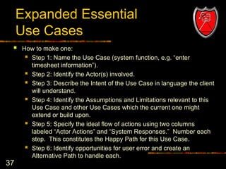
37. 37
Expanded Essential
Use Cases
How to make one:
Step 1: Name the Use Case (system function, e.g. “enter
timesheet information”).
Step 2: Identify the Actor(s) involved.
Step 3: Describe the Intent of the Use Case in language the client
will understand.
Step 4: Identify the Assumptions and Limitations relevant to this
Use Case and other Use Cases which the current one might
extend or build upon.
Step 5: Specify the ideal flow of actions using two columns
labeled “Actor Actions” and “System Responses.” Number each
step. This constitutes the Happy Path for this Use Case.
Step 6: Identify opportunities for user error and create an
Alternative Path to handle each.
38. 38
Postconditions
Postconditions (or success guarantees)
state what always must be true for a use
case to succeed. Avoid the obvious, but
clearly document any that are not obvious.
This is one of the most important parts of
a use case.
39. 39
Conditions and Branching
Stick to the “Happy Path,” “Sunny Day
Scenario,” Typical Flow, or Basic Flow (all
names for the same basic idea) in the
main section and defer all conditional
sections and branching to the extensions
or alternate flows.
40. 40
Warning
Use cases should not be misused to imitate
function specification by successive iteration
Don’t refine them until the program is fully
specified
The uses relation should only be used when
the same scenario is encountered more
than once
41. 41
Use Cases not an OO idea
Use Cases are not an Object-Oriented
methodology. They are common in
structured development as well.
However, the Unified Process encourages
use-case driven development.
42. 42
Use case levels
User-goal level
A complete process from the view point of a
user to meet a goal of the user, roughly
corresponding to an elementary business
process.
Subfunction level
Details steps to support a user goal.
43. 43
Use-case driven development
Requirements are primarily recorded in
the Use Case model.
Iterations are planned around
implementing particular Use Cases.
Use Case Realizations drive design.
Use Case often influence the way user
manuals are organized.
44. 44
Use Cases are always wrong!
Written documentation gives the illusion of
authority and correctness, but it is an illusion.
Use cases give a preliminary understanding that
users and developers can discuss and agree on.
But there should be constant feedback from
customers in the development process to correct
missing information and misinformation before it
jeopardizes the functionality of the program.
#36: The Expanded Essential Use Case is a transition document between the Analysis phase and the Design phase of software development. During this transition, documents are created less and less in langage of the client, and more and more in the language of the computer programmer. For Expanded Essential Use Cases there are two main goals: 1) to give the client an idea of what it will be like for the user to actually use the system and 2) to give the developer a start on developing system objects and pseudocode.
With the Expanded Essential Use Case, the developer will be able to identify major events during system use and translate them into event contracts and function specifications.
Each specification must describe something tangible and testable so that once the system has been completed it can be demonstrated that the Use Case was satisfied.
#37: The Expanded Essential Use Case is a transition document between the Analysis phase and the Design phase of software development. During this transition, documents are created less and less in langage of the client, and more and more in the language of the computer programmer. For Expanded Essential Use Cases there are two main goals: 1) to give the client an idea of what it will be like for the user to actually use the system and 2) to give the developer a start on developing system objects and pseudocode.
With the Expanded Essential Use Case, the developer will be able to identify major events during system use and translate them into event contracts and function specifications.
Each specification must describe something tangible and testable so that once the system has been completed it can be demonstrated that the Use Case was satisfied.