![International Journal of Power Electronics and Drive Systems (IJPEDS)
Vol. 12, No. 3, September 2021, pp. 1644~1658
ISSN: 2088-8694, DOI: 10.11591/ijpeds.v12.i3.pp1644-1658 1644
Journal homepage: http://ijpeds.iaescore.com
Using Y-source network as a connector between turbine and
network in the structure of variable speed wind turbine
Mahmoud Zadehbagheri1
, Tole Sutikno2
, Rahim Ildarabadi3
1
Department of Electrical Engineering, Islamic Azad University, Yasooj Branch, Yasooj, Iran
2
Department of Electrical Engineering, Universitas Ahmad Dahlan, Yogyakarta, Indonesia
2
Embedded System and Power Electronics Research Group, Yogyakarta, Indonesia
3
Department of Electrical Engineering, Hakim Sabzevari University, Sabzevar, Iran
Article Info ABSTRACT
Article history:
Received Apr 26, 2021
Revised Jun 27, 2021
Accepted Jul 8, 2021
Environmental factors such as air pollution and increase in global warming
by using polluting fuels are the most important reasons of using renewable
and clean energy that runs in global community. Wind energy is one of the
most suitable and widely used kind of renewable energy which had been in
consideration so well. This paper introduces an electric power generation
system of wind based on Y-source and improved Y-source inverter to deliver
optimal electrical power to the network. This new converter is from
impedance source converters family. This presented converter has more
degrees of freedom to adjust voltage gain and modulation. Also, by limiting
the range of simultaneous control (shooting through) while it maintains the
highest power of maximizer, it can operate in higher modulation range. This
causes the reduce of stress in switching and thus it will improve the quality
of output. Recommended system had been simulated in MATLAB/Simulink
and shown results indicate accurate functionality.
Keywords:
PMSG
Power generation system
Renewable energy
Wind energy
Wind turbine
Y-source inverter
Y-source network
This is an open access article under the CC BY-SA license.
Corresponding Author:
Mahmoud Zadehbagheri
Department of Electrical Engineering
Islamic Azad University, Yasooj Branch, Yasooj, Iran
Email: mzadehbagheri@gmail.com
1. INTRODUCTION
Using clean and renewable energy had been major concern for global communities and been
introduced as an important and vital matter. Environmental factors such as air pollution and increase in
global warming by using polluting fuels are the most important reasons of using renewable and clean energy.
Another advantage of using renewable energy sources is minimizing the size of power production units and
increasing the distributed generation units, the proximity of the units of production and consumption of
electric power and thus reduce losses and increase efficiency [1]–[22]. One of the highly used renewable
energy that had been in consideration is wind energy [1], [4], [14], [16], [19], [20], [23], [24]. Using wind
energy specially in windy areas in addition to the economic saving, increased quality will also be delivered.
Electric power generation system from wind energy has been divided into 4 parts: i) wind turbine, ii) electric
generators, iii) power electric devices, and iv) controlling systems. Which by increase in this industry and
technology there has been much progress in these sections and power electric devices, different generators
and control systems had been presented [25]. For example, with progress in materials science and further
showing off the permanent magnet machines, using wind energy in different speed without gearbox is highly
regarded. Thus, study of the electrical power generator systems from wind energy based on stimulating
converters with permanent magnet is essential from different points of view.](https://image.slidesharecdn.com/21328-41398-2-pb-220128064335/85/Using-Y-source-network-as-a-connector-between-turbine-and-network-in-the-structure-of-variable-speed-wind-turbine-1-320.jpg)
![Int J Pow Elec & Dri Syst ISSN: 2088-8694
Using Y-source network as a connector between turbine and network in the … (Mahmoud Zadehbagheri)
1645
In the field of power electronic devices, there had been more different suggestions with unique
features presented which the most important one is using one boost converter and source voltage inverter.
Electric power generation systems from wind energy with different speed has many positive features such as:
small size, high efficiency, lower installation cost and lower maintenance cost, compare to systems with fixed
speed. Considering permanent magnet generators (PMGs) that can connect to the network directly and
without using gearbox, has attracted more attention [26]–[31]. Hence, the purpose of this paper considering
the importance of the power electric devices in delivering electric power to the network (connector between
wind turbine and the network), is to suggest using Y-source network in variable speed wind turbine systems
based on permanent magnet machines as electronic converter. Mainly voltage source inverters only can show
buck performance (reducing) as a result, the AC output voltage will be limited by DC voltage source. Also,
in renewable energy applications input DC voltage fluctuates in a wide range and so there is need for buck-
boost function. To overcome this problem, firstly we use DC/DC converter which it is placed between the
source and inverter. By adding a DC/DC converter the structure will have two stages. In two stages structure
due to the lack of optimum combination, efficiency of the system and its performance will extremely reduce.
To fix these problems, impedance source inverter had been introduced, while they are single-stage due to the
removal dead time solving the DC bass short connection problem, they have high reliability. By introducing
these converters study field of many such as modulation, modeling, control is provided for the converters
[32]. Although buck-boost converter topology which is used to convert DC/AC as theory can boost the
voltage to any desired value, but the ability of these converters boosting will be limited by passive elements
and all the factors [33]. Specially in high duties of self-charging current cause massive losses in passive
elements and this cause instability and limiting the boost of voltage. Impedance networks cover the entire
range of power electronics, converting completely from converter and rectifier to converting phase and
frequency. There have been many different structures to solve limitations and problems of traditional
structures of voltage source and current source for impedance network converters in [4][34]–[37]. Placement
and proper implementation of the impedance supply network with switching and the appropriate setting,
reduce the power converting levels in power system chains. This improves reliability, stability and
improvement and also efficiency. The general scheme of impedance source converters structure with
different switch for different applications is shown in Figure 1 [32], [38].
Figure 1. General scheme of impedance source converters structure with different switch for different
applications [3]
So far, there has been many impedance source networks with the ability of maximizing which the
most important one is Z-source [39]–[46]. Features of this converter let researchers to think about solving the
problems of this structures and present structures like quasi-Z, embedded-Z, tapped-inductor, T-source, 𝛤-
source impedance source. Y-source converter has been introduced recently and is used as DC/DC and
AC/DC with three coils which had been coupled [34]. This converter has many different features. The
interest of this converter in equal duties is different to other converters and has more freedom to (the number
of turns of coils and switch timing (𝑑𝑠𝑡)) adjust the interest of voltage compare to classic impedance source
converters [34], [47]. Theoretical point of view, by adjusting the number of turns in coils 𝑑𝑠𝑡to any value, we
can see the increase in voltage [23]. In the following proposed system, variable speed wind turbine based on
Y-source inverter has been investigated and the results have been provided.](https://image.slidesharecdn.com/21328-41398-2-pb-220128064335/85/Using-Y-source-network-as-a-connector-between-turbine-and-network-in-the-structure-of-variable-speed-wind-turbine-2-320.jpg)
![ ISSN: 2088-8694
Int J Pow Elec & Dri Syst, Vol. 12, No. 3, September 2021 : 1644 – 1658
1646
2. THE PROPOSED WIND TURBINE SYSTEM
Proposed system based on Y-source inverter and permanent magnet synchronous generator (PMSG)
shown in Figure 2. In the following, we will discuss different parts of the proposed system.
PMSG
Grid
Y-Source Inverter
Rectifier
Figure 2. proposed system scheme
2.1. Modeling of wind turbine
To obtain a proper expression of wind energy, this energy must be measured in some way.
Calculating this energy with simple rules of classical physics, the kinetic energy of wind will be calculated as
(1).
𝐸𝑤𝑖𝑛𝑑 =
1
2
𝑚𝑉
𝑤
2
(1)
In this equation m is equivalent to mass of a volume of air passing through the turbine. It is assumed that the
total volume of wind moving at the same speed of 𝑉
𝑤. Wind speed unit is meter per second m/s assuming
constant speed of volume of wind hitting turbine blades, and a period of time t. We can define the mass as
(2).
𝑚 = 𝜌𝐴𝑉
𝑤𝑡 = 𝜌𝜋𝑅2
𝑉
𝑤𝑡 (2)
which ρ is air density, A the area swept by the turbine blades and R is the radius of the turbine blade.
Substituting (2) in relation (1) to the kinetic energy of the wind will be expressed as (3).
𝐸𝑤𝑖𝑛𝑑 =
1
3
𝜌𝜋𝑅2
𝑉
𝑤
3
𝑡 (3)
Using (3), the real power in wind power in every moment of time will be calculated as (4).
𝑃𝑤𝑖𝑛𝑑 =
𝐸𝑤𝑖𝑛𝑑
𝑡
=
1
2
𝜌𝜋𝑅2
𝑉
𝑤
3
(4)
This (4) shows that wind energy is heavily dependent on the wind speed. The affiliation with the
cube of wind speed is specified. So, a slight change in wind speed will create significant change in wind
energy. Also, it is possible to get more energy from the wind by increasing the radius of the turbine blades.
However, calculated power in (4) is the potential of wind power which is been calculated in wind speed 𝑉
𝑤
and R radius of turbine blade. From this amount, only a portion of that is converted into mechanical energy.
This percentage will be calculated as Albert Betz determined in 1919 by presenting this method [48]. Based
on this method, when the turbine blades are in wind direction, the wind speed reduce, as a result received
energy by turbine will be less than maximum energy in the wind speed. The relationship between received
energy by turbine, Pturbine, and maximum energy of wind, Pwind, and power factor of wind turbine, Cp, is as
(5).
𝐶𝑝 =
𝑃𝑡𝑢𝑟𝑏𝑖𝑛𝑒
𝑃𝑤𝑖𝑛𝑑
(5)](https://image.slidesharecdn.com/21328-41398-2-pb-220128064335/85/Using-Y-source-network-as-a-connector-between-turbine-and-network-in-the-structure-of-variable-speed-wind-turbine-3-320.jpg)
![Int J Pow Elec & Dri Syst ISSN: 2088-8694
Using Y-source network as a connector between turbine and network in the … (Mahmoud Zadehbagheri)
1647
This ratio is calculated as [7]:
𝐶𝑝 = 𝑐1(𝑐2
1
𝛼
− 𝑐3𝛽 − 𝑐4𝛽𝑥
− 𝑐5)𝑒−𝑐6
1
𝛼 (6)
1
𝛼
=
1
𝜆+0/08𝛽
−
0/035
1+𝛽3 (7)
𝜆 =
𝜔𝑚𝑅
𝑉𝑊
(8)
In (6), (7) and (8), 𝛽 is the angle of rotor blade which is shown in the Figure 3. 𝜆 is the severity rate
of speed of wind turbine and 𝜔𝑚 is angular velocity of the generator and wind turbine. Constant values (c1
and c6) depend on type of turbine [49]. In the angle 𝛽 = 0 maximum power is available.
At the end the equation of turbine blade is as (9).
𝑃𝑡𝑢𝑟𝑏𝑖𝑛𝑒 =
1
2
𝜌𝜋𝑅2
𝐶𝑝(𝜆, 𝛽)𝑉𝑊
3
(9)
Turbine mechanical torque, 𝑇𝑚, is obtained from (10).
𝑇𝑚 =
1
2
𝜌𝜋𝑅2𝐶𝑝(𝜆,𝛽)𝑉𝑤
3
𝜔𝑚
(10)
The following will be the simulation of wind, the effect of 𝛽 on Cp has been investigated and ratio
of highly optimized speed 𝜆opt, which 𝐶𝑝𝑜𝑝𝑡
is produced because of that, had been calculated. To gain this
goal C1 to C6 parameters as Table 1. To simulate the wind, in here we have used linear form which is like
increasing and decreasing of gradient.
Figure 3. Turbine blade’s angle diagram.
Table 1. C1 to C6 constants
C1 C2 C3 C4 C5 C6
0/5 116 0/5 0 5 21
2.2. Modeling of permanent magnet synchronous generator (PMSG)
The dynamic model of electric machines is necessary for investigating the dynamic conditions and
potential errors. Dynamic modelling based is on voltage equations, flow, flux-flow and park conversion. In
electric machines depends on input and output variables, different models can be simulated. In here based on
the functionality of this generator in combination with wind turbine and selected control system, the speed of
machine as entering and three-phase current of machines as output is considered for turbine-generator. Thus,
the equations will change as (11), (12) and (13) [50], [51].
𝑖𝑑𝑠 =
1
𝑠
(−𝑣𝑑𝑠−𝑅𝑠𝑖𝑑𝑠+𝜔𝑒𝐿𝑞𝑖𝑞𝑠)
𝐿𝑑
(11)
𝑖𝑞𝑠 =
1
𝑠
(−𝑣𝑞𝑠−𝑅𝑠𝑖𝑞𝑠−𝜔𝑒𝐿𝑑𝑖𝑑𝑠+𝜔𝑒𝜆𝑀)
𝐿𝑞
(12)](https://image.slidesharecdn.com/21328-41398-2-pb-220128064335/85/Using-Y-source-network-as-a-connector-between-turbine-and-network-in-the-structure-of-variable-speed-wind-turbine-4-320.jpg)
![ ISSN: 2088-8694
Int J Pow Elec & Dri Syst, Vol. 12, No. 3, September 2021 : 1644 – 1658
1648
𝐼𝑆 = √𝑖𝑑𝑠
2
+ 𝑖𝑞𝑠
2 (13)
The power delivered to the load can be calculated by (14) and (15).
𝑃𝑆 = 𝑃𝑚 − 𝑃𝑐𝑢𝑠 = 𝑇𝑒
𝜔𝑒
𝑝
− 3𝑅𝑠𝐼𝑆
2
(14)
𝑃𝑆 = 𝑃𝑚 − 𝑃𝑐𝑢𝑠 = 𝑇𝑒
𝜔𝑒
𝑝
− 3𝑅𝑠𝐼𝑆
2
(15)
2.3. Control system
The inverter control system is used to control active power and reactive power injected to the
network and maximum control is shown in Figure 4. The control system has two parts: i) MPPT, and ii)
active and reactive power control of the exchange with the network.
2.3.1. MPPT control system
There is need for MPPT control for adjusting the speed of rotor to get the highest power from wind
turbine [52]–[61]. Because the output voltage is not constant and it become short-circuit because of the
switches sometimes, for controlling signal we use capacitor voltage which is constant.
Figure 4. The control system considered for the proposed wind turbine system
The equation (16) shows the relationship between capacitor (C2) and output voltage [51], [62], [63].
𝑉𝐶2
= (1 − 𝐷)𝑉
𝑜 (16)
And according to the equation 𝑉
𝑜 =
1
1−𝐷(1+1+𝑛21/1−𝑛32)
𝑉𝑖𝑛 = 𝐵𝑉𝑖𝑛 and placement in the above equation, the
relation between the capacitor voltage C2 and the input voltage is as (17).
𝑉𝐶2
= (1 − 𝐷)
1
1 − 𝐷(1 + 1 + 𝑛21/1 − 𝑛32)
𝑉𝑖𝑛
𝑉𝐶2
= (1 − 𝐷)
1
1−𝐸𝐷
𝑉𝑖𝑛 (17)
Thus, the signal controller according to the number of courses intended for the windings is calculated as (18).
𝐷𝑠𝑐 =
𝑉𝐼𝑛−𝑉𝐶2
𝑉𝐼𝑛−𝐸𝑉𝐶2
(18)
2.3.2. Control of active and reactive power delivered to the network
Active power (P) and reactive power (Q) obtained from (19) and (20).](https://image.slidesharecdn.com/21328-41398-2-pb-220128064335/85/Using-Y-source-network-as-a-connector-between-turbine-and-network-in-the-structure-of-variable-speed-wind-turbine-5-320.jpg)
![Int J Pow Elec & Dri Syst ISSN: 2088-8694
Using Y-source network as a connector between turbine and network in the … (Mahmoud Zadehbagheri)
1649
𝑃 =
3
2
(𝑣𝑑𝑖𝑑 + 𝑣𝑞𝑖𝑞) (19)
𝑄 =
3
2
(𝑣𝑑𝑖𝑑 + 𝑣𝑞𝑖𝑞) (20)
𝑣𝑑, 𝑣𝑞 is network voltage, 𝑖𝑑, 𝑖𝑞 injected current to the network in the frame of reference d-q. If the
reference voltage become as network voltage, then vq=0. Thus, the equations (19) and (20) will change to
(21) and (22) [51], [64]–[67].
𝑃 =
3
2
𝑣𝑑𝑖𝑑 (21)
𝑃 =
3
2
𝑣𝑑𝑖𝑑 (22)
From the (21) and (22), we realize that we can control active and reactive injected powers to the
network by controlling id and iq. To do that there are two directions of control will be considered. In the first
direction by adding the amount of reference for reactive power, id will be adjusted and the amount of
reference of id to reach power factor the unit will be considered as zero. In the next direction by capacitor
voltage in inverter mode or output voltage in converter mode for controlling the output active power, iq will
be adjusted [62], [66], [68].
3. METHOD
In this section, to investigate wind turbine systems there is an opinion based on Y-source inverter,
the system simulated is shown. We used MATLAB/Simulink for simulation as Figure 5. Simulation
parameters are shown in Tables 2 and 3. Voltage curve DC based on rotor speed is shown in Figure 6. We
use this curve to find highest point of power and control inverter. To find this curve firstly in a few different
speed (0.6-1.26 p.u) rotor and in highest power delivered to the network, the speed of rotor and DC link
voltage has been measured which is shown in red in the figure. Then a polynomial function is guessed based
on that which shows DC link voltage behavior change with respect to rotor speed changes in all the speeds
with a very good approximation and low error. For comparison the improved Y-Source converter has been
simulated. The simulated circuit is shown in Figure 7.
Figure 5. Simulated model in MATLAB/Simulink
Table 2. PM Generator Parameters
Amounts Parameters
0.9585(Ω) R
5.25(mH) Ld, Lq
4 P
6329(kg.cm2
) J
Table 3. Simulation Parameters
Amounts Parameters
10(kHz) Switching Frequency (Fs)
76(v)) Network Effective Voltage
0.5(mH) Filter Capacitor (C)
20:41:20 Conversion Ratio (N1:N2:N3)](https://image.slidesharecdn.com/21328-41398-2-pb-220128064335/85/Using-Y-source-network-as-a-connector-between-turbine-and-network-in-the-structure-of-variable-speed-wind-turbine-6-320.jpg)


![Int J Pow Elec & Dri Syst ISSN: 2088-8694
Using Y-source network as a connector between turbine and network in the … (Mahmoud Zadehbagheri)
1655
Numerical comparison of the proposed system THD with systems including traditional Y-Source and Z-
Source is given in Table 5.
Table 5. Numerical comparison of THD (IYSI, YSI, ZSI)
THD Converter
2.04% Improved Y-Source inverter
2.14% Y-Source inverter
3.56% Z-Source inverter
5. CONCLUSION
As mentioned before, environmental factors such as air pollution and the increase in global warming
by using polluting fuels are the most important reasons of using renewable and clean energy that runs in
global community. Wind energy is one of the most suitable and widely used kind of renewable energy which
had been in consideration so well. In this paper, we discussed a new structure of wind turbine based on Y-
source inverter as connector between the network and generator. All parts of the suggested system were
discussed and at the end the result of simulation which it was done by MATLAB/SIMULINK software were
shown. The result shows the correct functionality of the system and controlling system under changes of the
wind speed.
REFERENCES
[1] A. D. Hansen and L. H. Hansen, “Wind turbine concept market penetration over 10 years (1995-2004),” Wind
Energy, vol. 10, no. 1, pp. 81–97, 2007, doi: 10.1002/we.210.
[2] K. Hema and Muralidharan, “Attractive lunar power creation using enormity and clean stream tube,” Indones. J.
Electr. Eng. Comput. Sci., vol. 9, no. 1, pp. 85–88, 2018, doi: 10.11591/ijeecs.v9.i1.pp85-88.
[3] V. Kalyanasundaram, S. George Fernandez, K. Vijayakumar, and S. Vidyasagar, “A two stage battery charger for
EV charging applications,” Indones. J. Electr. Eng. Comput. Sci., vol. 19, no. 2, pp. 593–599, 2020, doi:
10.11591/ijeecs.v19.i2.pp593-599.
[4] A. M. Al-Modaffer, A. A. Chlaihawi, and H. A. Wahhab, “Non-isolated multiple input multilevel output DC-DC
converter for hybrid power system,” Indones. J. Electr. Eng. Comput. Sci., vol. 19, no. 2, pp. 635–643, 2020, doi:
10.11591/ijeecs.v19.i2.pp635-643.
[5] V. Lavanya and N. S. Kumar, “Control strategies for seamless transfer between the grid-connected and islanded
modes of a microgrid system,” Int. J. Electr. Comput. Eng., vol. 10, no. 5, pp. 4490–4506, 2020, doi:
10.11591/ijece.v10i5.pp4490-4506.
[6] M. N. Raj and J. Pasupuleti, “Performance assessment of a 619kW photovoltaic power plant in the northeast of
peninsular Malaysia,” Indones. J. Electr. Eng. Comput. Sci., vol. 20, no. 1, pp. 9–15, 2020, doi:
10.11591/ijeecs.v20.i1.pp9-15.
[7] E. Hendawi, “A high performance grid connected PV system based on HERIC transformerless inverter,” Indones.
J. Electr. Eng. Comput. Sci., vol. 20, no. 2, pp. 602–612, 2020, doi: 10.11591/ijeecs.v20.i2.pp602-612.
[8] F. Z. Kessaissia, A. Zegaoui, R. Taleb, C. Fares, and M. Aillerie, “Design of experiments approach for modeling
the electrical response of a photovoltaic module,” Indones. J. Electr. Eng. Comput. Sci., vol. 20, no. 3, pp. 1140–
1147, 2020, doi: 10.11591/ijeecs.v20.i3.pp1140-1147.
[9] E. Z. Ahmad et al., “Recent advances in passive cooling methods for photovoltaic performance enhancement,” Int.
J. Electr. Comput. Eng., vol. 11, no. 1, pp. 146–154, 2021, doi: 10.11591/ijece.v11i1.pp146-154.
[10] S. R. Salkuti, “Electrochemical batteries for smart grid applications,” Int. J. Electr. Comput. Eng., vol. 11, no. 3,
pp. 1849–1856, 2021, doi: 10.11591/ijece.v11i3.pp1849-1856.
[11] A. R. Alzyoud et al., “The impact of integration of solar farms on the power losses, voltage profile and short circuit
level in the distribution system,” Bull. Electr. Eng. Informatics, vol. 10, no. 3, pp. 1129–1141, 2021, doi:
10.11591/eei.v10i3.1909.
[12] A. Kurniawan and A. Harumwidiah, “An evaluation of the artificial neural network based on the estimation of daily
average global solar radiation in the city of Surabaya,” Indones. J. Electr. Eng. Comput. Sci., vol. 22, no. 3, pp.
1245–1250, 2021, doi: 10.11591/ijeecs.v22.i3.pp1245-1250.
[13] A. M. Farayola, A. N. Hasan, and A. Ali, “Optimization of PV systems using data mining and regression learner
MPPT techniques,” Indones. J. Electr. Eng. Comput. Sci., vol. 10, no. 3, pp. 1080–1089, 2018, doi:
10.11591/ijeecs.v10.i3.pp1080-1089.
[14] E. Jarmouni, A. Mouhsen, M. Lamhammedi, and Z. Benizza, “Energy management in connected and disconnected
mode of a photovoltaic system with a battery storage using an artificial neural network technique,” Indones. J.
Electr. Eng. Comput. Sci., vol. 23, no. 1, pp. 54–62, 2021, doi: 10.11591/ijeecs.v23.i1.pp54-92.
[15] A. Kurniawan and E. Shintaku, “Two-step artificial neural network to estimate the solar radiation at Java Island,”
Int. J. Electr. Comput. Eng., vol. 11, no. 4, pp. 3559–3566, 2021, doi: 10.11591/ijece.v11i4.pp3559-3566.
[16] S. Samal and P. K. Hota, “Wind energy fed upqc system for power quality improvement,” Bull. Electr. Eng.
Informatics, vol. 7, no. 3, pp. 495–504, 2018, doi: 10.11591/eei.v7i3.945.](https://image.slidesharecdn.com/21328-41398-2-pb-220128064335/85/Using-Y-source-network-as-a-connector-between-turbine-and-network-in-the-structure-of-variable-speed-wind-turbine-12-320.jpg)
![ ISSN: 2088-8694
Int J Pow Elec & Dri Syst, Vol. 12, No. 3, September 2021 : 1644 – 1658
1656
[17] K. Suresh, P. Anusha, S. Najma, B. I. Rajkumar, C. Rami Reddy, and B. Prasanna Lakshmi, “A passive islanding
detection method for hybrid distributed generation system under balanced islanding,” Indones. J. Electr. Eng.
Comput. Sci., vol. 14, no. 1, pp. 9–19, 2019, doi: 10.11591/ijeecs.v14.i1.pp9-19.
[18] D. H. Al-Mamoori, M. H. Aljanabi, O. M. Neda, Z. H. Al-Tameemi, and A. A. Alobaidi, “Evaluation of gas fuel
and biofuel usage in turbine,” Indones. J. Electr. Eng. Comput. Sci., vol. 14, no. 3, pp. 1097–1104, 2019, doi:
10.11591/ijeecs.v14.i3.pp1097-1104.
[19] A. Ahmed and T. Jiang, “Impact of compressed air energy storage system into diesel power plant with wind power
penetration,” Int. J. Electr. Comput. Eng., vol. 9, no. 3, pp. 1553–1560, 2019, doi: 10.11591/ijece.v9i3.pp1553-
1560.
[20] A. Badawi et al., “Evaluation of wind power for electrical energy generation in the mediterranean coast of Palestine
for 14 years,” Int. J. Electr. Comput. Eng., vol. 9, no. 4, pp. 2212–2219, 2019, doi: 10.11591/ijece.v9i4.pp2212-
2219.
[21] I. Yadav, S. K. Maurya, and G. K. Gupta, “A literature review on industrially accepted MPPT techniques for solar
PV system,” Int. J. Electr. Comput. Eng., vol. 10, no. 2, pp. 2117–2127, 2020, doi: 10.11591/ijece.v10i2.pp2117-
2127.
[22] S. Munisekhar, G. V Marutheswar, P. Sujatha, and K. R. Vadivelu, “A novel approach for the fastest MPPT
tracking algorithm for a PV array fed BLDC motor driven air conditioning system,” Indones. J. Electr. Eng.
Comput. Sci., vol. 18, no. 2, pp. 622–628, 2020, doi: 10.11591/ijeecs.v18.i2.pp622-628.
[23] S. Heier, Grid integration of wind energy: onshore and offshore conversion systems. John Wiley & Sons, 2014.
[24] B. K. Ramasamy, A. Palaniappan, and S. M. Yakoh, “Direct-drive low-speed wind energy conversion system
incorporating axial-type permanent magnet generator and Z-source inverter with sensorless maximum power point
tracking controller,” IET Renew. Power Gener., vol. 7, no. 3, pp. 284–295, 2013, doi: 10.1049/iet-rpg.2012.0248.
[25] A. Petersson, L. Harnefors, and T. Thiringer, “Evaluation of current control methods for wind turbines using
doubly-fed induction machines,” IEEE Trans. Power Electron., vol. 20, no. 1, pp. 227–235, 2005, doi:
10.1109/TPEL.2004.839785.
[26] A. M. Yasin and M. F. Alsayed, “Fuzzy logic power management for a PV/wind microgrid with backup and
storage systems,” Int. J. Electr. Comput. Eng., vol. 11, no. 4, pp. 2876–2888, 2021, doi:
10.11591/ijece.v11i4.pp2876-2888.
[27] S. A. Hussien, M. A. Deab, and N. S. Hosny, “Improving the delivered power quality from WECS to the grid based
on PMSG control model,” Int. J. Electr. Comput. Eng., vol. 10, no. 6, pp. 6349–6360, 2020, doi:
10.11591/ijece.v10i6.pp6349-6360.
[28] M. Makhad, M. Zazi, and A. Loulijat, “Nonlinear control of WECS based on PMSG for optimal power extraction,”
Int. J. Electr. Comput. Eng., vol. 10, no. 3, pp. 2815–2823, 2020, doi: 10.11591/ijece.v10i3.pp2815-2823.
[29] A. Chaithanakulwat, “Development of DC voltage control from wind turbines using proportions and integrals for
Three-phase grid-connected inverters,” Int. J. Electr. Comput. Eng., vol. 10, no. 2, pp. 1701–1711, 2020, doi:
10.11591/ijece.v10i2.pp1701-1711.
[30] D. Chinna Kullay Reddy, S. Satyanarayana, and V. Ganesh, “Design of hybrid solar wind energy system in a
microgrid with MPPT techniques,” Int. J. Electr. Comput. Eng., vol. 8, no. 2, pp. 730–740, 2018, doi:
10.11591/ijece.v8i2.pp730-740.
[31] K. S. Gaeid, M. A. Asker, N. N. Tawfeeq, and S. R. Mahdi, “Computer simulation of PMSM motor with five phase
inverter control using signal processing techniques,” Int. J. Electr. Comput. Eng., vol. 8, no. 5, pp. 3697–3710,
2018, doi: 10.11591/ijece.v8i5.pp3697-3710.
[32] Y. P. Siwakoti, F. Z. Peng, F. Blaabjerg, P. C. Loh, and G. E. Town, “Impedance-source networks for electric
power conversion Part I: A topological review,” IEEE Trans. Power Electron., vol. 30, no. 2, pp. 699–716, 2015,
doi: 10.1109/TPEL.2014.2313746.
[33] K. J. Sinu and G. Ranganathan, “A novel hydro powered online power converter for marine lighting applications,”
Indones. J. Electr. Eng. Comput. Sci., vol. 9, no. 1, pp. 15–19, 2018, doi: 10.11591/ijeecs.v9.i1.pp15-19.
[34] M. Ado, A. Jusoh, and T. Sutikno, “Asymmetric quasi impedance source buck-boost converter,” Int. J. Electr.
Comput. Eng., vol. 10, no. 2, pp. 2128–2138, 2020, doi: 10.11591/ijece.v10i2.pp2128-2138.
[35] J. R. Rahul and K. Annamalai, “Multistring seven-level quasi Z-source based asymmetrical inverter,” Indones. J.
Electr. Eng. Comput. Sci., vol. 15, no. 1, pp. 88–94, 2019, doi: 10.11591/ijeecs.v15.i1.pp88-94.
[36] M. Ado, A. Jusoh, A. U. Mutawakkil, and T. Sutikno, “Dynamic model of a DC-DC quasi-Z-source converter (q-
ZSC),” Int. J. Electr. Comput. Eng., vol. 9, no. 3, pp. 1585–1597, 2019, doi: 10.11591/ijece.v9i3.pp1585-1597.
[37] C. R. Balamurugan and K. Vijayalakshmi, “Comparative analysis of various Z-source based five level cascaded H-
bridge multilevel inverter,” Bull. Electr. Eng. Informatics, vol. 7, no. 1, pp. 1–14, 2018, doi: 10.11591/eei.v7i1.656.
[38] H. Abu-Rub, A. Iqbal, S. M. Ahmed, F. Z. Peng, Y. Li, and G. Baoming, “Quasi-Z-source inverter-based
photovoltaic generation system with maximum power tracking control using ANFIS,” IEEE Trans. Sustain.
Energy, vol. 4, no. 1, pp. 11–20, 2013, doi: 10.1109/TSTE.2012.2196059.
[39] T. A. Hussein and L. A. Mohammed, “Detailed Simulink implementation for induction motor control based on
space vector pulse width modulation SVPWM,” Indones. J. Electr. Eng. Comput. Sci., vol. 22, no. 3, pp. 1251–
1262, 2021, doi: 10.11591/ijeecs.v22.i3.pp1251-1262.
[40] D. Chowdhury, M. S. Miah, M. F. Hossain, and U. Sarker, “Implementation of a grid-tied emergency back-up
power supply for medium and low power applications,” Int. J. Electr. Comput. Eng., vol. 10, no. 6, pp. 6233–6243,
2020, doi: 10.11591/IJECE.V10I6.PP6233-6243.
[41] D. Karthikeyan, K. Vijayakumar, D. S. Kumar, and D. Krishnachaitanya, “Mathematical analysis of cost function](https://image.slidesharecdn.com/21328-41398-2-pb-220128064335/85/Using-Y-source-network-as-a-connector-between-turbine-and-network-in-the-structure-of-variable-speed-wind-turbine-13-320.jpg)
![Int J Pow Elec & Dri Syst ISSN: 2088-8694
Using Y-source network as a connector between turbine and network in the … (Mahmoud Zadehbagheri)
1657
and reliability condition for new proposed multilevel inverter topology,” Indones. J. Electr. Eng. Comput. Sci., vol.
20, no. 2, pp. 654–661, 2020, doi: 10.11591/ijeecs.v20.i2.pp654-661.
[42] S. Kamalakkannan and D. Kirubakaran, “Solar energy based impedance-source inverter for grid system,” Int. J.
Electr. Comput. Eng., vol. 9, no. 1, pp. 102–108, 2019, doi: 10.11591/ijece.v9i1.pp102-109.
[43] T. Pangaribowo, W. M. Utomo, A. A. Bakar, and D. S. Khaerudini, “Battery charging and discharging control of a
hybrid energy system using microcontroller,” Indones. J. Electr. Eng. Comput. Sci., vol. 17, no. 2, pp. 575–582,
2019, doi: 10.11591/ijeecs.v17.i2.pp575-582.
[44] M. Ado, A. Jusoh, and T. Sutikno, “Extended family of DC-DC quasi-Z-source converters,” Int. J. Electr. Comput.
Eng., vol. 9, no. 6, pp. 4540–4555, 2019, doi: 10.11591/ijece.v9i6.pp4540-4555.
[45] S. M. Irshad and G. P. Ramesh, “High gain power generation based on hybrid renewable energy for AC load
application,” Indones. J. Electr. Eng. Comput. Sci., vol. 12, no. 3, pp. 1195–1202, 2018, doi:
10.11591/ijeecs.v12.i3.pp1195-1202.
[46] D. Vidhyalakshmi and K. Balaji, “Performance of bidirectional converter based on grid application,” Indones. J.
Electr. Eng. Comput. Sci., vol. 12, no. 3, pp. 1203–1210, 2018, doi: 10.11591/ijeecs.v12.i3.pp1203-1210.
[47] M. Ado, A. Jusoh, T. Sutikno, M. H. Muda, and Z. A. Arfeen, “Dual output DC-DC quasi impedance source
converter,” Int. J. Electr. Comput. Eng., vol. 10, no. 4, pp. 3988–3998, 2020, doi: 10.11591/ijece.v10i4.pp3988-
3998.
[48] C.-M. Ong, Dynamic simulation of electric machinery: using MATLAB/SIMULINK, vol. 5. Prentice hall PTR
Upper Saddle River, NJ, 1998.
[49] Y. P. Siwakoti, P. C. Loh, F. Blaabjerg, and G. E. Town, “Effects of leakage inductances on magnetically coupled
y-source network,” IEEE Trans. Power Electron., vol. 29, no. 11, pp. 5662–5666, 2014, doi:
10.1109/TPEL.2014.2322856.
[50] A. Prasai, J. S. Yim, D. Divan, A. Bendre, and S. K. Sul, “A new architecture for offshore wind farms,” IEEE
Trans. Power Electron., vol. 23, no. 3, pp. 1198–1204, 2008, doi: 10.1109/TPEL.2008.921194.
[51] M. Zadehbagheri, R. Ildarabadi, and M. Baghaeinejad, “A novel method for modeling and simulation of
asymmetrical impedance-source converters,” Int. J. Eng. Trans. B Appl., vol. 31, no. 5, pp. 741–751, 2018, doi:
10.5829/ije.2018.31.05b.09.
[52] W. Obaid, A.-K. Hamid, and C. Ghenai, “Solar/wind pumping system with forecasting in Sharjah, United Arab
Emirates,” Int. J. Electr. Comput. Eng., vol. 11, no. 4, pp. 2752–2759, 2021, doi: 10.11591/ijece.v11i4.pp2752-
2759.
[53] Z. Hamadouche, M. Khiat, and M. A. Iqbal, “Intelligent voltage regulator for distributed generation-based
network,” Indones. J. Electr. Eng. Comput. Sci., vol. 23, no. 1, pp. 98–109, 2021, doi: 10.11591/ijeecs.v23.i1.pp98-
109.
[54] Y. Dbaghi, S. Farhat, M. Mediouni, H. Essakhi, and A. Elmoudden, “Indirect power control of DFIG based on
wind turbine operating in MPPT using backstepping approach,” Int. J. Electr. Comput. Eng., vol. 11, no. 3, pp.
1951–1961, 2021, doi: 10.11591/ijece.v11i3.pp1951-1961.
[55] W. Obaid, A.-K. Hamid, and C. Ghenai, “Hybrid solar/wind/diesel water pumping system in Dubai, United Arab
Emirates,” Int. J. Electr. Comput. Eng., vol. 11, no. 3, pp. 2062–2067, 2021, doi: 10.11591/ijece.v11i3.pp2062-
2067.
[56] A. E. Said and A. M. Eial Awwad, “A comparative study of performance of ac and DC electric drive control
systems with variable moment of inertia,” Bull. Electr. Eng. Informatics, vol. 10, no. 2, pp. 588–597, 2021, doi:
10.11591/eei.v10i2.2768.
[57] M. M. Alhato and S. Bouallègue, “Thermal exchange optimization based control of a doubly fed induction
generator in wind energy conversion systems,” Indones. J. Electr. Eng. Comput. Sci., vol. 20, no. 3, pp. 1252–1260,
2020, doi: 10.11591/ijeecs.v20.i3.pp1252-1260.
[58] M. O. Rachedi, M. L. Saidi, and F. Arbaoui, “MPPT control design for variable speed wind turbine,” Int. J. Electr.
Comput. Eng., vol. 10, no. 5, pp. 4604–4614, 2020, doi: 10.11591/ijece.v10i5.pp4604-4614.
[59] M. Z. M. Tumari, M. M. Zahar, and M. A. Ahmad, “Optimal tuning of a wind plant energy production based on
improved grey wolf optimizer,” Bull. Electr. Eng. Informatics, vol. 10, no. 1, pp. 23–30, 2020, doi:
10.11591/eei.v10i1.2509.
[60] H. A. Aroussi, E. M. Ziani, M. Bouderbala, and B. Bossoufi, “Enhancement of the direct power control applied to
DFIG-WECS,” Int. J. Electr. Comput. Eng., vol. 10, no. 1, pp. 35–46, 2020, doi: 10.11591/ijece.v10i1.pp35-46.
[61] Y. Baala and S. Bri, “Torque estimator using MPPT method for wind turbines,” Int. J. Electr. Comput. Eng., vol.
10, no. 2, pp. 1208–1219, 2020, doi: 10.11591/ijece.v10i2.pp1208-1219.
[62] T. Ahmed and S. Mekhilef, “Semi-Z-source inverter topology for grid-connected photovoltaic system,” IET Power
Electron., vol. 8, no. 1, pp. 63–75, 2015, doi: 10.1049/iet-pel.2013.0486.
[63] F. Khosravi, N. A. Azli, and A. Kaykhosravi, “Design of a reduced component count single-phase to three-phase
quasi-z-source converter,” IET Power Electron., vol. 7, no. 3, pp. 489–495, 2014, doi: 10.1049/iet-pel.2013.0096.
[64] Y. Li, S. Jiang, J. G. Cintron-Rivera, and F. Z. Peng, “Modeling and control of quasi-z-source inverter for
distributed generation applications,” IEEE Trans. Ind. Electron., vol. 60, no. 4, pp. 1532–1541, 2013, doi:
10.1109/TIE.2012.2213551.
[65] B. Ge et al., “An energy-stored quasi-Z-source inverter for application to photovoltaic power system,” IEEE Trans.
Ind. Electron., vol. 60, no. 10, pp. 4468–4481, 2013, doi: 10.1109/TIE.2012.2217711.
[66] Y. P. Siwakoti and G. E. Town, “Y -Source Inverter,” 2014, [Online]. Available: file:///D:/4. ris/siwakoti2014 Y -
Source Inverter.pdf.
[67] M. Zadehbagheri, R. Ildarabadi, and M. B. Nejad, “Review of dynamic voltage restorer application for](https://image.slidesharecdn.com/21328-41398-2-pb-220128064335/85/Using-Y-source-network-as-a-connector-between-turbine-and-network-in-the-structure-of-variable-speed-wind-turbine-14-320.jpg)
![ ISSN: 2088-8694
Int J Pow Elec & Dri Syst, Vol. 12, No. 3, September 2021 : 1644 – 1658
1658
compensation of voltage harmonics in power systems,” Indones. J. Electr. Eng. Comput. Sci., vol. 5, no. 1, pp. 58–
71, 2017, doi: 10.11591/ijeecs.v5.i1.pp58-71.
[68] R. R. Ahrabi and M. R. Banaei, “Improved Y-source DC-AC converter with continuous input current,” IET Power
Electron., vol. 9, no. 4, pp. 801–808, 2016, doi: 10.1049/iet-pel.2014.0947.
BIOGRAPHIES OF AUTHORS
Mahmoud Zadehbagheri was born in Yasouj, Iran in October 1989. In 2003 he received his
B.S. in Electrical Engineering from Kashan University and in 2008 he received his M.S. in
Electrical Engineering from the Islamic Azad University, Najafabad Branch. He received the
PhD degree in Electrical Engineering from Hakim Sabzvari University & Universiti Teknologi
Malaysia (UTM), Johor, Skudai, Malaysia in 2017. He is with the faculty of the Electrical
Engineering Department, Islamic Azad University of Yasouj. His research interests include the
fields of power electronics, electrical machines and drives, FACTS devices and Power Quality.
Tole Sutikno is a Lecturer in Electrical Engineering Department at the Universitad Ahmad
Dahlan (UAD), Yogyakarta, Indonesia. He received his B.Eng., M.Eng. and Ph.D. degrees in
Electrical Engineering from Universitas Diponegoro, Universitas Gadjah Mada and Universiti
Teknologi Malaysia, in 1999, 2004 and 2016, respectively. He has been an Associate Professor
in UAD, Yogyakarta, Indonesia since 2008. He is currently an Editor-in-Chief of the
TELKOMNIKA since 2005, and the Head of the Embedded Systems and Power Electronics
Research Group since 2016. His research interests include the field of digital design, industrial
applications, industrial electronics, industrial informatics, power electronics, motor drives,
renewable energy, FPGA applications, embedded system, artificial intelligence, intelligent
control and digital library.
Rahim Ildarabadi was born in Sabzevar, Iran in 1975. He received the PhD degree from
Ferdowsi University of Mashhad in 2010. He is a full-time faculty member at Sabzevar, Hakim
Sabzevari University. His main area of interests is automation system, electrical machine drive,
renewable energy, instruments and measurement. He is currently an Assistant Professor of
electrical engineering at Hakim SabzevariUniversity.](https://image.slidesharecdn.com/21328-41398-2-pb-220128064335/85/Using-Y-source-network-as-a-connector-between-turbine-and-network-in-the-structure-of-variable-speed-wind-turbine-15-320.jpg)
Using Y-source network as a connector between turbine and network in the structure of variable speed wind turbine
- 1. International Journal of Power Electronics and Drive Systems (IJPEDS) Vol. 12, No. 3, September 2021, pp. 1644~1658 ISSN: 2088-8694, DOI: 10.11591/ijpeds.v12.i3.pp1644-1658 1644 Journal homepage: http://ijpeds.iaescore.com Using Y-source network as a connector between turbine and network in the structure of variable speed wind turbine Mahmoud Zadehbagheri1 , Tole Sutikno2 , Rahim Ildarabadi3 1 Department of Electrical Engineering, Islamic Azad University, Yasooj Branch, Yasooj, Iran 2 Department of Electrical Engineering, Universitas Ahmad Dahlan, Yogyakarta, Indonesia 2 Embedded System and Power Electronics Research Group, Yogyakarta, Indonesia 3 Department of Electrical Engineering, Hakim Sabzevari University, Sabzevar, Iran Article Info ABSTRACT Article history: Received Apr 26, 2021 Revised Jun 27, 2021 Accepted Jul 8, 2021 Environmental factors such as air pollution and increase in global warming by using polluting fuels are the most important reasons of using renewable and clean energy that runs in global community. Wind energy is one of the most suitable and widely used kind of renewable energy which had been in consideration so well. This paper introduces an electric power generation system of wind based on Y-source and improved Y-source inverter to deliver optimal electrical power to the network. This new converter is from impedance source converters family. This presented converter has more degrees of freedom to adjust voltage gain and modulation. Also, by limiting the range of simultaneous control (shooting through) while it maintains the highest power of maximizer, it can operate in higher modulation range. This causes the reduce of stress in switching and thus it will improve the quality of output. Recommended system had been simulated in MATLAB/Simulink and shown results indicate accurate functionality. Keywords: PMSG Power generation system Renewable energy Wind energy Wind turbine Y-source inverter Y-source network This is an open access article under the CC BY-SA license. Corresponding Author: Mahmoud Zadehbagheri Department of Electrical Engineering Islamic Azad University, Yasooj Branch, Yasooj, Iran Email: [email protected] 1. INTRODUCTION Using clean and renewable energy had been major concern for global communities and been introduced as an important and vital matter. Environmental factors such as air pollution and increase in global warming by using polluting fuels are the most important reasons of using renewable and clean energy. Another advantage of using renewable energy sources is minimizing the size of power production units and increasing the distributed generation units, the proximity of the units of production and consumption of electric power and thus reduce losses and increase efficiency [1]–[22]. One of the highly used renewable energy that had been in consideration is wind energy [1], [4], [14], [16], [19], [20], [23], [24]. Using wind energy specially in windy areas in addition to the economic saving, increased quality will also be delivered. Electric power generation system from wind energy has been divided into 4 parts: i) wind turbine, ii) electric generators, iii) power electric devices, and iv) controlling systems. Which by increase in this industry and technology there has been much progress in these sections and power electric devices, different generators and control systems had been presented [25]. For example, with progress in materials science and further showing off the permanent magnet machines, using wind energy in different speed without gearbox is highly regarded. Thus, study of the electrical power generator systems from wind energy based on stimulating converters with permanent magnet is essential from different points of view.
- 2. Int J Pow Elec & Dri Syst ISSN: 2088-8694 Using Y-source network as a connector between turbine and network in the … (Mahmoud Zadehbagheri) 1645 In the field of power electronic devices, there had been more different suggestions with unique features presented which the most important one is using one boost converter and source voltage inverter. Electric power generation systems from wind energy with different speed has many positive features such as: small size, high efficiency, lower installation cost and lower maintenance cost, compare to systems with fixed speed. Considering permanent magnet generators (PMGs) that can connect to the network directly and without using gearbox, has attracted more attention [26]–[31]. Hence, the purpose of this paper considering the importance of the power electric devices in delivering electric power to the network (connector between wind turbine and the network), is to suggest using Y-source network in variable speed wind turbine systems based on permanent magnet machines as electronic converter. Mainly voltage source inverters only can show buck performance (reducing) as a result, the AC output voltage will be limited by DC voltage source. Also, in renewable energy applications input DC voltage fluctuates in a wide range and so there is need for buck- boost function. To overcome this problem, firstly we use DC/DC converter which it is placed between the source and inverter. By adding a DC/DC converter the structure will have two stages. In two stages structure due to the lack of optimum combination, efficiency of the system and its performance will extremely reduce. To fix these problems, impedance source inverter had been introduced, while they are single-stage due to the removal dead time solving the DC bass short connection problem, they have high reliability. By introducing these converters study field of many such as modulation, modeling, control is provided for the converters [32]. Although buck-boost converter topology which is used to convert DC/AC as theory can boost the voltage to any desired value, but the ability of these converters boosting will be limited by passive elements and all the factors [33]. Specially in high duties of self-charging current cause massive losses in passive elements and this cause instability and limiting the boost of voltage. Impedance networks cover the entire range of power electronics, converting completely from converter and rectifier to converting phase and frequency. There have been many different structures to solve limitations and problems of traditional structures of voltage source and current source for impedance network converters in [4][34]–[37]. Placement and proper implementation of the impedance supply network with switching and the appropriate setting, reduce the power converting levels in power system chains. This improves reliability, stability and improvement and also efficiency. The general scheme of impedance source converters structure with different switch for different applications is shown in Figure 1 [32], [38]. Figure 1. General scheme of impedance source converters structure with different switch for different applications [3] So far, there has been many impedance source networks with the ability of maximizing which the most important one is Z-source [39]–[46]. Features of this converter let researchers to think about solving the problems of this structures and present structures like quasi-Z, embedded-Z, tapped-inductor, T-source, 𝛤- source impedance source. Y-source converter has been introduced recently and is used as DC/DC and AC/DC with three coils which had been coupled [34]. This converter has many different features. The interest of this converter in equal duties is different to other converters and has more freedom to (the number of turns of coils and switch timing (𝑑𝑠𝑡)) adjust the interest of voltage compare to classic impedance source converters [34], [47]. Theoretical point of view, by adjusting the number of turns in coils 𝑑𝑠𝑡to any value, we can see the increase in voltage [23]. In the following proposed system, variable speed wind turbine based on Y-source inverter has been investigated and the results have been provided.
- 3. ISSN: 2088-8694 Int J Pow Elec & Dri Syst, Vol. 12, No. 3, September 2021 : 1644 – 1658 1646 2. THE PROPOSED WIND TURBINE SYSTEM Proposed system based on Y-source inverter and permanent magnet synchronous generator (PMSG) shown in Figure 2. In the following, we will discuss different parts of the proposed system. PMSG Grid Y-Source Inverter Rectifier Figure 2. proposed system scheme 2.1. Modeling of wind turbine To obtain a proper expression of wind energy, this energy must be measured in some way. Calculating this energy with simple rules of classical physics, the kinetic energy of wind will be calculated as (1). 𝐸𝑤𝑖𝑛𝑑 = 1 2 𝑚𝑉 𝑤 2 (1) In this equation m is equivalent to mass of a volume of air passing through the turbine. It is assumed that the total volume of wind moving at the same speed of 𝑉 𝑤. Wind speed unit is meter per second m/s assuming constant speed of volume of wind hitting turbine blades, and a period of time t. We can define the mass as (2). 𝑚 = 𝜌𝐴𝑉 𝑤𝑡 = 𝜌𝜋𝑅2 𝑉 𝑤𝑡 (2) which ρ is air density, A the area swept by the turbine blades and R is the radius of the turbine blade. Substituting (2) in relation (1) to the kinetic energy of the wind will be expressed as (3). 𝐸𝑤𝑖𝑛𝑑 = 1 3 𝜌𝜋𝑅2 𝑉 𝑤 3 𝑡 (3) Using (3), the real power in wind power in every moment of time will be calculated as (4). 𝑃𝑤𝑖𝑛𝑑 = 𝐸𝑤𝑖𝑛𝑑 𝑡 = 1 2 𝜌𝜋𝑅2 𝑉 𝑤 3 (4) This (4) shows that wind energy is heavily dependent on the wind speed. The affiliation with the cube of wind speed is specified. So, a slight change in wind speed will create significant change in wind energy. Also, it is possible to get more energy from the wind by increasing the radius of the turbine blades. However, calculated power in (4) is the potential of wind power which is been calculated in wind speed 𝑉 𝑤 and R radius of turbine blade. From this amount, only a portion of that is converted into mechanical energy. This percentage will be calculated as Albert Betz determined in 1919 by presenting this method [48]. Based on this method, when the turbine blades are in wind direction, the wind speed reduce, as a result received energy by turbine will be less than maximum energy in the wind speed. The relationship between received energy by turbine, Pturbine, and maximum energy of wind, Pwind, and power factor of wind turbine, Cp, is as (5). 𝐶𝑝 = 𝑃𝑡𝑢𝑟𝑏𝑖𝑛𝑒 𝑃𝑤𝑖𝑛𝑑 (5)
- 4. Int J Pow Elec & Dri Syst ISSN: 2088-8694 Using Y-source network as a connector between turbine and network in the … (Mahmoud Zadehbagheri) 1647 This ratio is calculated as [7]: 𝐶𝑝 = 𝑐1(𝑐2 1 𝛼 − 𝑐3𝛽 − 𝑐4𝛽𝑥 − 𝑐5)𝑒−𝑐6 1 𝛼 (6) 1 𝛼 = 1 𝜆+0/08𝛽 − 0/035 1+𝛽3 (7) 𝜆 = 𝜔𝑚𝑅 𝑉𝑊 (8) In (6), (7) and (8), 𝛽 is the angle of rotor blade which is shown in the Figure 3. 𝜆 is the severity rate of speed of wind turbine and 𝜔𝑚 is angular velocity of the generator and wind turbine. Constant values (c1 and c6) depend on type of turbine [49]. In the angle 𝛽 = 0 maximum power is available. At the end the equation of turbine blade is as (9). 𝑃𝑡𝑢𝑟𝑏𝑖𝑛𝑒 = 1 2 𝜌𝜋𝑅2 𝐶𝑝(𝜆, 𝛽)𝑉𝑊 3 (9) Turbine mechanical torque, 𝑇𝑚, is obtained from (10). 𝑇𝑚 = 1 2 𝜌𝜋𝑅2𝐶𝑝(𝜆,𝛽)𝑉𝑤 3 𝜔𝑚 (10) The following will be the simulation of wind, the effect of 𝛽 on Cp has been investigated and ratio of highly optimized speed 𝜆opt, which 𝐶𝑝𝑜𝑝𝑡 is produced because of that, had been calculated. To gain this goal C1 to C6 parameters as Table 1. To simulate the wind, in here we have used linear form which is like increasing and decreasing of gradient. Figure 3. Turbine blade’s angle diagram. Table 1. C1 to C6 constants C1 C2 C3 C4 C5 C6 0/5 116 0/5 0 5 21 2.2. Modeling of permanent magnet synchronous generator (PMSG) The dynamic model of electric machines is necessary for investigating the dynamic conditions and potential errors. Dynamic modelling based is on voltage equations, flow, flux-flow and park conversion. In electric machines depends on input and output variables, different models can be simulated. In here based on the functionality of this generator in combination with wind turbine and selected control system, the speed of machine as entering and three-phase current of machines as output is considered for turbine-generator. Thus, the equations will change as (11), (12) and (13) [50], [51]. 𝑖𝑑𝑠 = 1 𝑠 (−𝑣𝑑𝑠−𝑅𝑠𝑖𝑑𝑠+𝜔𝑒𝐿𝑞𝑖𝑞𝑠) 𝐿𝑑 (11) 𝑖𝑞𝑠 = 1 𝑠 (−𝑣𝑞𝑠−𝑅𝑠𝑖𝑞𝑠−𝜔𝑒𝐿𝑑𝑖𝑑𝑠+𝜔𝑒𝜆𝑀) 𝐿𝑞 (12)
- 5. ISSN: 2088-8694 Int J Pow Elec & Dri Syst, Vol. 12, No. 3, September 2021 : 1644 – 1658 1648 𝐼𝑆 = √𝑖𝑑𝑠 2 + 𝑖𝑞𝑠 2 (13) The power delivered to the load can be calculated by (14) and (15). 𝑃𝑆 = 𝑃𝑚 − 𝑃𝑐𝑢𝑠 = 𝑇𝑒 𝜔𝑒 𝑝 − 3𝑅𝑠𝐼𝑆 2 (14) 𝑃𝑆 = 𝑃𝑚 − 𝑃𝑐𝑢𝑠 = 𝑇𝑒 𝜔𝑒 𝑝 − 3𝑅𝑠𝐼𝑆 2 (15) 2.3. Control system The inverter control system is used to control active power and reactive power injected to the network and maximum control is shown in Figure 4. The control system has two parts: i) MPPT, and ii) active and reactive power control of the exchange with the network. 2.3.1. MPPT control system There is need for MPPT control for adjusting the speed of rotor to get the highest power from wind turbine [52]–[61]. Because the output voltage is not constant and it become short-circuit because of the switches sometimes, for controlling signal we use capacitor voltage which is constant. Figure 4. The control system considered for the proposed wind turbine system The equation (16) shows the relationship between capacitor (C2) and output voltage [51], [62], [63]. 𝑉𝐶2 = (1 − 𝐷)𝑉 𝑜 (16) And according to the equation 𝑉 𝑜 = 1 1−𝐷(1+1+𝑛21/1−𝑛32) 𝑉𝑖𝑛 = 𝐵𝑉𝑖𝑛 and placement in the above equation, the relation between the capacitor voltage C2 and the input voltage is as (17). 𝑉𝐶2 = (1 − 𝐷) 1 1 − 𝐷(1 + 1 + 𝑛21/1 − 𝑛32) 𝑉𝑖𝑛 𝑉𝐶2 = (1 − 𝐷) 1 1−𝐸𝐷 𝑉𝑖𝑛 (17) Thus, the signal controller according to the number of courses intended for the windings is calculated as (18). 𝐷𝑠𝑐 = 𝑉𝐼𝑛−𝑉𝐶2 𝑉𝐼𝑛−𝐸𝑉𝐶2 (18) 2.3.2. Control of active and reactive power delivered to the network Active power (P) and reactive power (Q) obtained from (19) and (20).
- 6. Int J Pow Elec & Dri Syst ISSN: 2088-8694 Using Y-source network as a connector between turbine and network in the … (Mahmoud Zadehbagheri) 1649 𝑃 = 3 2 (𝑣𝑑𝑖𝑑 + 𝑣𝑞𝑖𝑞) (19) 𝑄 = 3 2 (𝑣𝑑𝑖𝑑 + 𝑣𝑞𝑖𝑞) (20) 𝑣𝑑, 𝑣𝑞 is network voltage, 𝑖𝑑, 𝑖𝑞 injected current to the network in the frame of reference d-q. If the reference voltage become as network voltage, then vq=0. Thus, the equations (19) and (20) will change to (21) and (22) [51], [64]–[67]. 𝑃 = 3 2 𝑣𝑑𝑖𝑑 (21) 𝑃 = 3 2 𝑣𝑑𝑖𝑑 (22) From the (21) and (22), we realize that we can control active and reactive injected powers to the network by controlling id and iq. To do that there are two directions of control will be considered. In the first direction by adding the amount of reference for reactive power, id will be adjusted and the amount of reference of id to reach power factor the unit will be considered as zero. In the next direction by capacitor voltage in inverter mode or output voltage in converter mode for controlling the output active power, iq will be adjusted [62], [66], [68]. 3. METHOD In this section, to investigate wind turbine systems there is an opinion based on Y-source inverter, the system simulated is shown. We used MATLAB/Simulink for simulation as Figure 5. Simulation parameters are shown in Tables 2 and 3. Voltage curve DC based on rotor speed is shown in Figure 6. We use this curve to find highest point of power and control inverter. To find this curve firstly in a few different speed (0.6-1.26 p.u) rotor and in highest power delivered to the network, the speed of rotor and DC link voltage has been measured which is shown in red in the figure. Then a polynomial function is guessed based on that which shows DC link voltage behavior change with respect to rotor speed changes in all the speeds with a very good approximation and low error. For comparison the improved Y-Source converter has been simulated. The simulated circuit is shown in Figure 7. Figure 5. Simulated model in MATLAB/Simulink Table 2. PM Generator Parameters Amounts Parameters 0.9585(Ω) R 5.25(mH) Ld, Lq 4 P 6329(kg.cm2 ) J Table 3. Simulation Parameters Amounts Parameters 10(kHz) Switching Frequency (Fs) 76(v)) Network Effective Voltage 0.5(mH) Filter Capacitor (C) 20:41:20 Conversion Ratio (N1:N2:N3)
- 7. ISSN: 2088-8694 Int J Pow Elec & Dri Syst, Vol. 12, No. 3, September 2021 : 1644 – 1658 1650 Figure 6. DC link voltage changes curve based on changes in rotor speed Figure 7. Simulated converter in MATLAB/Simulink software 4. RESULTS AND DISCUSSION Wind model applied to the system based on Figure 4 which the speed reduces from 12 to 10 m/s. In Figure 8, changes in the speed of rotor by changing wind speed is shown in different time. Considering the curve of the changes in rotor speed and changes in wind speed curve, it is obvious that the speed of rotor has changed for delivering the highest power from turbine with the change of the speed of wind. To know these changes, we need to look at Figures 9 and 10, which in order they show mechanical and electrical curve. It is shown that after a short period of time the mechanical power curve of turbine production has reached the highest power and followed it (based on wind speed). DC link voltage inverter and its big scheme is in Figure 11. As it can be understood from Figure 11, voltage level changes from maximum to zero and vice versa, the reason of these changes are short circuits in the inverter bases in transition at the same time. Thus, in this situation, we use Y-source converter capacitor voltage to control MPPT and control active and reactive power which injected to the network. Inverter capacitor (C1, C2) voltages is shown in Figure 12 and Figure 13. Figure 8. Rotor speed (p.u) according to variations in wind speed. Figure 9. Curve of turbine mechanical power Figure 10. Active and reactive power which is delivered to the network under changes of wind speed. 0.2 0.3 0.4 0.5 0.6 0.7 0.8 0.9 1 0 0.5 1 1.5 2 2.5 3 3.5 4 Time (seconds) Rotor Speed (Pu) 0.1 0.2 0.3 0.4 0.5 0.6 0.7 0.8 0.9 1 -1 -0.5 0 0.5 1 1.5 Exteracted Mechanical Power Maximum mechanical Power 0.1 0.2 0.3 0.4 0.5 0.6 0.7 0.8 0.9 1 0 500 1000 1500 Time (second) Active and Reactive Power Actve Power Reactive Power
- 8. Int J Pow Elec & Dri Syst ISSN: 2088-8694 Using Y-source network as a connector between turbine and network in the … (Mahmoud Zadehbagheri) 1651 (a) (b) Figure 11. DC link voltage inverter, (a) Inverter DC link voltage, (b) Inverter DC link voltage in magnified mode under changes of wind speed Figure 12. Capacitor voltage (C2) under changes of wind speed Figure 13. Capacitor voltage curve (C1) under changes of wind speed. Injection current to the network is shown in Figure 14. In order to obtain the system efficiency (η) at different wind speeds, we will first obtain the transmission power to the network and the maximum mechanical power at different speeds, and then from the relation of η%= 𝑃grid 𝑃max-mec × 100, we will obtain the system efficiency. The power delivered to the network at wind different speeds and the efficiency of the proposed system are shown in Figure 15, and Figure 16, respectively. It is worth noting that this system could also be simulated based on the Y-Source DC-DC converter or the Improved Y-Source (DC/DC) converter, but this has led to the use of more switches and increased losses, and THD Also increases and it is not economically viable. Figure 17 and Figure 18 show that the system met the requirements for connecting to the network because the level of capacitor voltage is kept in a constant level and reactive power exchange to the network is almost zero (unity power factor). Figure 14. Injection current to the network by the proposed system Figure 15. Power delivered to the network by the proposed system. 0.2 0.3 0.4 0.5 0.6 0.7 0.8 0.9 1 0 50 100 150 200 250 Time (seconds) Vinv(V) 0.998 0.9982 0.9984 0.9986 0.9988 0.999 0.9992 0.9994 0.9996 0.9998 1 0 50 100 150 200 250 Time (seconds) Vinv(V) 0.2 0.3 0.4 0.5 0.6 0.7 0.8 0.9 1 0 50 100 150 200 250 300 Time (seconds) Vc2(V) 0.2 0.3 0.4 0.5 0.6 0.7 0.8 0.9 1 40 50 60 70 80 Time (seconds) Vc1(V) 0.2 0.3 0.4 0.5 0.6 0.7 0.8 0.9 1 -50 0 50 Time (seconds) Inet(A) Phase A Phase B Phase C 5 6 7 8 9 10 11 12 13 14 15 0 200 400 600 800 1000 1200 Wind Speed (m/s) Electrical Power (w)
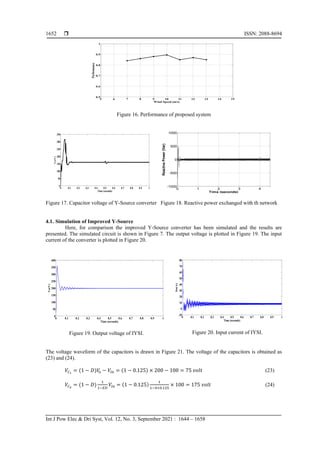
- 9. ISSN: 2088-8694 Int J Pow Elec & Dri Syst, Vol. 12, No. 3, September 2021 : 1644 – 1658 1652 Figure 16. Performance of proposed system Figure 17. Capacitor voltage of Y-Source converter Figure 18. Reactive power exchanged with th network 4.1. Simulation of Improved Y-Source Here, for comparison the improved Y-Source converter has been simulated and the results are presented. The simulated circuit is shown in Figure 7. The output voltage is plotted in Figure 19. The input current of the converter is plotted in Figure 20. Figure 19. Output voltage of IYSI. Figure 20. Input current of IYSI. The voltage waveform of the capacitors is drawn in Figure 21. The voltage of the capacitors is obtained as (23) and (24). 𝑉𝐶1 = (1 − 𝐷)𝑉 𝑜 − 𝑉𝑖𝑛 = (1 − 0.125) × 200 − 100 = 75 𝑣𝑜𝑙𝑡 (23) 𝑉𝐶2 = (1 − 𝐷) 1 1−𝐸𝐷 𝑉𝑖𝑛 = (1 − 0.125) 1 1−4×0.125 × 100 = 175 𝑣𝑜𝑙𝑡 (24) 5 6 7 8 9 10 11 12 13 14 15 0.5 0.6 0.7 0.8 0.9 1 Wind Speed (m/s) Performance 0 0.1 0.2 0.3 0.4 0.5 0.6 0.7 0.8 0.9 1 0 50 100 150 200 250 300 350 Time (seconds) Vc(V) 0 1 2 3 4 -1000 -500 0 500 1000 Time (seconds) Reactive Power (Var) 0 0.1 0.2 0.3 0.4 0.5 0.6 0.7 0.8 0.9 1 0 50 100 150 200 250 300 350 400 Time (seconds) Vo(V) 0 0.1 0.2 0.3 0.4 0.5 0.6 0.7 0.8 0.9 1 -10 0 10 20 30 40 50 60 70 80 Time (seconds) Iin(A)
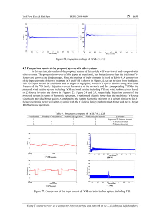
- 10. Int J Pow Elec & Dri Syst ISSN: 2088-8694 Using Y-source network as a connector between turbine and network in the … (Mahmoud Zadehbagheri) 1653 Figure 21. Capacitors voltage of IYSI (C1, C2) 4.2. Comparison results of the proposed system with other systems In this section, the results of the proposed system of this article will be reviewed and compared with other systems. The proposed converter of this paper, as mentioned, has better features than the traditional Y- Source and corrects its disadvantages. First, the number of their elements is listed in Table 4. A comparison of the input currents of the two inverters IYS and IYSI is shown in Figure 22. As can be seen from the figure, the IYSI input stream is continuous and its ripple is negligible, which is a special feature along with other features of the YS family. Injection current harmonics to the network and the corresponding THD by the proposed wind turbine system including IYSI and wind turbine including YSI and wind turbine system based on Z-Source inverter are shown in Figures 23, Figure 24 and 25, respectively. Injection current of the proposed system in terms of harmonic spectrum, it performed slightly better than the traditional Y-Source system and provided better quality. Compared to the current harmonic spectrum of a system similar to the Z- Source electronic power converter, systems with the Y-Source family perform much better and have a lower THD harmonic spectrum. Table 4. Structures compare of IYSI, YSI, ZSI. Transformer Number of inductances Number of capacitors Semiconductor number Corverter 1 1 2 1 Improved Y-Source inverter 1 0 1 1 Y-Source inverter 0 2 2 1 Z-Source inverter IYSI (zoom) (IYSI) YSI (zoom) (YSI) Figure 22. Comparison of the input current of IYSI and wind turbine system including YSI. 0 0.1 0.2 0.3 0.4 0.5 0.6 0.7 0.8 0.9 1 -100 -50 0 50 100 150 200 250 Time (seconds) Vc1(V) 0 0.1 0.2 0.3 0.4 0.5 0.6 0.7 0.8 0.9 1 0 50 100 150 200 250 300 Time (seconds) Vc2(V) 0.9998 0.9999 1 0 5 10 15 20 Time (seconds) Iin(A) 0 0.1 0.2 0.3 0.4 0.5 0.6 0.7 0.8 0.9 1 -10 0 10 20 30 40 50 60 70 80 Time (seconds) Iin(A) 0.9998 0.9999 1 -10 -5 0 5 10 15 20 Time (seconds) Iin-Y-source(A) 0.2 0.3 0.4 0.5 0.6 0.7 0.8 0.9 1 -10 0 10 20 30 40 50 60 Time (seconds) Iin-Y-source(A)
- 11. ISSN: 2088-8694 Int J Pow Elec & Dri Syst, Vol. 12, No. 3, September 2021 : 1644 – 1658 1654 Figure 23. Injection current harmonics to the network and THD (IYSI) Figure 24. Injection current harmonics to the network and THD (YSI) Figure 25. Injection current harmonics to the network and THD (Z-Source) 0.2 0.205 0.21 0.215 0.22 0.225 0.23 -5 0 5 FFT window: 2 of 60 cycles of selected signal Time (s) 0 100 200 300 400 500 600 700 800 900 1000 0 0.2 0.4 0.6 0.8 1 1.2 1.4 Frequency (Hz) Fundamental (60Hz) = 9 , THD= 2.04% Mag (% of Fundamental) 0.2 0.205 0.21 0.215 0.22 0.225 0.23 -5 0 5 FFT window: 2 of 60 cycles of selected signal Time (s) 0 100 200 300 400 500 600 700 800 900 1000 0 0.2 0.4 0.6 0.8 1 1.2 1.4 1.6 Frequency (Hz) Fundamental (60Hz) = 9.013 , THD= 2.14% Mag (% of Fundamental) 0.3 0.305 0.31 0.315 0.32 0.325 0.33 -5 0 5 FFT window: 2 of 30 cycles of selected signal Time (s) 0 100 200 300 400 500 600 700 800 900 1000 0 0.5 1 1.5 2 2.5 Frequency (Hz) Fundamental (60Hz) = 5.266 , THD= 3.56% Mag (% of Fundamental)
- 12. Int J Pow Elec & Dri Syst ISSN: 2088-8694 Using Y-source network as a connector between turbine and network in the … (Mahmoud Zadehbagheri) 1655 Numerical comparison of the proposed system THD with systems including traditional Y-Source and Z- Source is given in Table 5. Table 5. Numerical comparison of THD (IYSI, YSI, ZSI) THD Converter 2.04% Improved Y-Source inverter 2.14% Y-Source inverter 3.56% Z-Source inverter 5. CONCLUSION As mentioned before, environmental factors such as air pollution and the increase in global warming by using polluting fuels are the most important reasons of using renewable and clean energy that runs in global community. Wind energy is one of the most suitable and widely used kind of renewable energy which had been in consideration so well. In this paper, we discussed a new structure of wind turbine based on Y- source inverter as connector between the network and generator. All parts of the suggested system were discussed and at the end the result of simulation which it was done by MATLAB/SIMULINK software were shown. The result shows the correct functionality of the system and controlling system under changes of the wind speed. REFERENCES [1] A. D. Hansen and L. H. Hansen, “Wind turbine concept market penetration over 10 years (1995-2004),” Wind Energy, vol. 10, no. 1, pp. 81–97, 2007, doi: 10.1002/we.210. [2] K. Hema and Muralidharan, “Attractive lunar power creation using enormity and clean stream tube,” Indones. J. Electr. Eng. Comput. Sci., vol. 9, no. 1, pp. 85–88, 2018, doi: 10.11591/ijeecs.v9.i1.pp85-88. [3] V. Kalyanasundaram, S. George Fernandez, K. Vijayakumar, and S. Vidyasagar, “A two stage battery charger for EV charging applications,” Indones. J. Electr. Eng. Comput. Sci., vol. 19, no. 2, pp. 593–599, 2020, doi: 10.11591/ijeecs.v19.i2.pp593-599. [4] A. M. Al-Modaffer, A. A. Chlaihawi, and H. A. Wahhab, “Non-isolated multiple input multilevel output DC-DC converter for hybrid power system,” Indones. J. Electr. Eng. Comput. Sci., vol. 19, no. 2, pp. 635–643, 2020, doi: 10.11591/ijeecs.v19.i2.pp635-643. [5] V. Lavanya and N. S. Kumar, “Control strategies for seamless transfer between the grid-connected and islanded modes of a microgrid system,” Int. J. Electr. Comput. Eng., vol. 10, no. 5, pp. 4490–4506, 2020, doi: 10.11591/ijece.v10i5.pp4490-4506. [6] M. N. Raj and J. Pasupuleti, “Performance assessment of a 619kW photovoltaic power plant in the northeast of peninsular Malaysia,” Indones. J. Electr. Eng. Comput. Sci., vol. 20, no. 1, pp. 9–15, 2020, doi: 10.11591/ijeecs.v20.i1.pp9-15. [7] E. Hendawi, “A high performance grid connected PV system based on HERIC transformerless inverter,” Indones. J. Electr. Eng. Comput. Sci., vol. 20, no. 2, pp. 602–612, 2020, doi: 10.11591/ijeecs.v20.i2.pp602-612. [8] F. Z. Kessaissia, A. Zegaoui, R. Taleb, C. Fares, and M. Aillerie, “Design of experiments approach for modeling the electrical response of a photovoltaic module,” Indones. J. Electr. Eng. Comput. Sci., vol. 20, no. 3, pp. 1140– 1147, 2020, doi: 10.11591/ijeecs.v20.i3.pp1140-1147. [9] E. Z. Ahmad et al., “Recent advances in passive cooling methods for photovoltaic performance enhancement,” Int. J. Electr. Comput. Eng., vol. 11, no. 1, pp. 146–154, 2021, doi: 10.11591/ijece.v11i1.pp146-154. [10] S. R. Salkuti, “Electrochemical batteries for smart grid applications,” Int. J. Electr. Comput. Eng., vol. 11, no. 3, pp. 1849–1856, 2021, doi: 10.11591/ijece.v11i3.pp1849-1856. [11] A. R. Alzyoud et al., “The impact of integration of solar farms on the power losses, voltage profile and short circuit level in the distribution system,” Bull. Electr. Eng. Informatics, vol. 10, no. 3, pp. 1129–1141, 2021, doi: 10.11591/eei.v10i3.1909. [12] A. Kurniawan and A. Harumwidiah, “An evaluation of the artificial neural network based on the estimation of daily average global solar radiation in the city of Surabaya,” Indones. J. Electr. Eng. Comput. Sci., vol. 22, no. 3, pp. 1245–1250, 2021, doi: 10.11591/ijeecs.v22.i3.pp1245-1250. [13] A. M. Farayola, A. N. Hasan, and A. Ali, “Optimization of PV systems using data mining and regression learner MPPT techniques,” Indones. J. Electr. Eng. Comput. Sci., vol. 10, no. 3, pp. 1080–1089, 2018, doi: 10.11591/ijeecs.v10.i3.pp1080-1089. [14] E. Jarmouni, A. Mouhsen, M. Lamhammedi, and Z. Benizza, “Energy management in connected and disconnected mode of a photovoltaic system with a battery storage using an artificial neural network technique,” Indones. J. Electr. Eng. Comput. Sci., vol. 23, no. 1, pp. 54–62, 2021, doi: 10.11591/ijeecs.v23.i1.pp54-92. [15] A. Kurniawan and E. Shintaku, “Two-step artificial neural network to estimate the solar radiation at Java Island,” Int. J. Electr. Comput. Eng., vol. 11, no. 4, pp. 3559–3566, 2021, doi: 10.11591/ijece.v11i4.pp3559-3566. [16] S. Samal and P. K. Hota, “Wind energy fed upqc system for power quality improvement,” Bull. Electr. Eng. Informatics, vol. 7, no. 3, pp. 495–504, 2018, doi: 10.11591/eei.v7i3.945.
- 13. ISSN: 2088-8694 Int J Pow Elec & Dri Syst, Vol. 12, No. 3, September 2021 : 1644 – 1658 1656 [17] K. Suresh, P. Anusha, S. Najma, B. I. Rajkumar, C. Rami Reddy, and B. Prasanna Lakshmi, “A passive islanding detection method for hybrid distributed generation system under balanced islanding,” Indones. J. Electr. Eng. Comput. Sci., vol. 14, no. 1, pp. 9–19, 2019, doi: 10.11591/ijeecs.v14.i1.pp9-19. [18] D. H. Al-Mamoori, M. H. Aljanabi, O. M. Neda, Z. H. Al-Tameemi, and A. A. Alobaidi, “Evaluation of gas fuel and biofuel usage in turbine,” Indones. J. Electr. Eng. Comput. Sci., vol. 14, no. 3, pp. 1097–1104, 2019, doi: 10.11591/ijeecs.v14.i3.pp1097-1104. [19] A. Ahmed and T. Jiang, “Impact of compressed air energy storage system into diesel power plant with wind power penetration,” Int. J. Electr. Comput. Eng., vol. 9, no. 3, pp. 1553–1560, 2019, doi: 10.11591/ijece.v9i3.pp1553- 1560. [20] A. Badawi et al., “Evaluation of wind power for electrical energy generation in the mediterranean coast of Palestine for 14 years,” Int. J. Electr. Comput. Eng., vol. 9, no. 4, pp. 2212–2219, 2019, doi: 10.11591/ijece.v9i4.pp2212- 2219. [21] I. Yadav, S. K. Maurya, and G. K. Gupta, “A literature review on industrially accepted MPPT techniques for solar PV system,” Int. J. Electr. Comput. Eng., vol. 10, no. 2, pp. 2117–2127, 2020, doi: 10.11591/ijece.v10i2.pp2117- 2127. [22] S. Munisekhar, G. V Marutheswar, P. Sujatha, and K. R. Vadivelu, “A novel approach for the fastest MPPT tracking algorithm for a PV array fed BLDC motor driven air conditioning system,” Indones. J. Electr. Eng. Comput. Sci., vol. 18, no. 2, pp. 622–628, 2020, doi: 10.11591/ijeecs.v18.i2.pp622-628. [23] S. Heier, Grid integration of wind energy: onshore and offshore conversion systems. John Wiley & Sons, 2014. [24] B. K. Ramasamy, A. Palaniappan, and S. M. Yakoh, “Direct-drive low-speed wind energy conversion system incorporating axial-type permanent magnet generator and Z-source inverter with sensorless maximum power point tracking controller,” IET Renew. Power Gener., vol. 7, no. 3, pp. 284–295, 2013, doi: 10.1049/iet-rpg.2012.0248. [25] A. Petersson, L. Harnefors, and T. Thiringer, “Evaluation of current control methods for wind turbines using doubly-fed induction machines,” IEEE Trans. Power Electron., vol. 20, no. 1, pp. 227–235, 2005, doi: 10.1109/TPEL.2004.839785. [26] A. M. Yasin and M. F. Alsayed, “Fuzzy logic power management for a PV/wind microgrid with backup and storage systems,” Int. J. Electr. Comput. Eng., vol. 11, no. 4, pp. 2876–2888, 2021, doi: 10.11591/ijece.v11i4.pp2876-2888. [27] S. A. Hussien, M. A. Deab, and N. S. Hosny, “Improving the delivered power quality from WECS to the grid based on PMSG control model,” Int. J. Electr. Comput. Eng., vol. 10, no. 6, pp. 6349–6360, 2020, doi: 10.11591/ijece.v10i6.pp6349-6360. [28] M. Makhad, M. Zazi, and A. Loulijat, “Nonlinear control of WECS based on PMSG for optimal power extraction,” Int. J. Electr. Comput. Eng., vol. 10, no. 3, pp. 2815–2823, 2020, doi: 10.11591/ijece.v10i3.pp2815-2823. [29] A. Chaithanakulwat, “Development of DC voltage control from wind turbines using proportions and integrals for Three-phase grid-connected inverters,” Int. J. Electr. Comput. Eng., vol. 10, no. 2, pp. 1701–1711, 2020, doi: 10.11591/ijece.v10i2.pp1701-1711. [30] D. Chinna Kullay Reddy, S. Satyanarayana, and V. Ganesh, “Design of hybrid solar wind energy system in a microgrid with MPPT techniques,” Int. J. Electr. Comput. Eng., vol. 8, no. 2, pp. 730–740, 2018, doi: 10.11591/ijece.v8i2.pp730-740. [31] K. S. Gaeid, M. A. Asker, N. N. Tawfeeq, and S. R. Mahdi, “Computer simulation of PMSM motor with five phase inverter control using signal processing techniques,” Int. J. Electr. Comput. Eng., vol. 8, no. 5, pp. 3697–3710, 2018, doi: 10.11591/ijece.v8i5.pp3697-3710. [32] Y. P. Siwakoti, F. Z. Peng, F. Blaabjerg, P. C. Loh, and G. E. Town, “Impedance-source networks for electric power conversion Part I: A topological review,” IEEE Trans. Power Electron., vol. 30, no. 2, pp. 699–716, 2015, doi: 10.1109/TPEL.2014.2313746. [33] K. J. Sinu and G. Ranganathan, “A novel hydro powered online power converter for marine lighting applications,” Indones. J. Electr. Eng. Comput. Sci., vol. 9, no. 1, pp. 15–19, 2018, doi: 10.11591/ijeecs.v9.i1.pp15-19. [34] M. Ado, A. Jusoh, and T. Sutikno, “Asymmetric quasi impedance source buck-boost converter,” Int. J. Electr. Comput. Eng., vol. 10, no. 2, pp. 2128–2138, 2020, doi: 10.11591/ijece.v10i2.pp2128-2138. [35] J. R. Rahul and K. Annamalai, “Multistring seven-level quasi Z-source based asymmetrical inverter,” Indones. J. Electr. Eng. Comput. Sci., vol. 15, no. 1, pp. 88–94, 2019, doi: 10.11591/ijeecs.v15.i1.pp88-94. [36] M. Ado, A. Jusoh, A. U. Mutawakkil, and T. Sutikno, “Dynamic model of a DC-DC quasi-Z-source converter (q- ZSC),” Int. J. Electr. Comput. Eng., vol. 9, no. 3, pp. 1585–1597, 2019, doi: 10.11591/ijece.v9i3.pp1585-1597. [37] C. R. Balamurugan and K. Vijayalakshmi, “Comparative analysis of various Z-source based five level cascaded H- bridge multilevel inverter,” Bull. Electr. Eng. Informatics, vol. 7, no. 1, pp. 1–14, 2018, doi: 10.11591/eei.v7i1.656. [38] H. Abu-Rub, A. Iqbal, S. M. Ahmed, F. Z. Peng, Y. Li, and G. Baoming, “Quasi-Z-source inverter-based photovoltaic generation system with maximum power tracking control using ANFIS,” IEEE Trans. Sustain. Energy, vol. 4, no. 1, pp. 11–20, 2013, doi: 10.1109/TSTE.2012.2196059. [39] T. A. Hussein and L. A. Mohammed, “Detailed Simulink implementation for induction motor control based on space vector pulse width modulation SVPWM,” Indones. J. Electr. Eng. Comput. Sci., vol. 22, no. 3, pp. 1251– 1262, 2021, doi: 10.11591/ijeecs.v22.i3.pp1251-1262. [40] D. Chowdhury, M. S. Miah, M. F. Hossain, and U. Sarker, “Implementation of a grid-tied emergency back-up power supply for medium and low power applications,” Int. J. Electr. Comput. Eng., vol. 10, no. 6, pp. 6233–6243, 2020, doi: 10.11591/IJECE.V10I6.PP6233-6243. [41] D. Karthikeyan, K. Vijayakumar, D. S. Kumar, and D. Krishnachaitanya, “Mathematical analysis of cost function
- 14. Int J Pow Elec & Dri Syst ISSN: 2088-8694 Using Y-source network as a connector between turbine and network in the … (Mahmoud Zadehbagheri) 1657 and reliability condition for new proposed multilevel inverter topology,” Indones. J. Electr. Eng. Comput. Sci., vol. 20, no. 2, pp. 654–661, 2020, doi: 10.11591/ijeecs.v20.i2.pp654-661. [42] S. Kamalakkannan and D. Kirubakaran, “Solar energy based impedance-source inverter for grid system,” Int. J. Electr. Comput. Eng., vol. 9, no. 1, pp. 102–108, 2019, doi: 10.11591/ijece.v9i1.pp102-109. [43] T. Pangaribowo, W. M. Utomo, A. A. Bakar, and D. S. Khaerudini, “Battery charging and discharging control of a hybrid energy system using microcontroller,” Indones. J. Electr. Eng. Comput. Sci., vol. 17, no. 2, pp. 575–582, 2019, doi: 10.11591/ijeecs.v17.i2.pp575-582. [44] M. Ado, A. Jusoh, and T. Sutikno, “Extended family of DC-DC quasi-Z-source converters,” Int. J. Electr. Comput. Eng., vol. 9, no. 6, pp. 4540–4555, 2019, doi: 10.11591/ijece.v9i6.pp4540-4555. [45] S. M. Irshad and G. P. Ramesh, “High gain power generation based on hybrid renewable energy for AC load application,” Indones. J. Electr. Eng. Comput. Sci., vol. 12, no. 3, pp. 1195–1202, 2018, doi: 10.11591/ijeecs.v12.i3.pp1195-1202. [46] D. Vidhyalakshmi and K. Balaji, “Performance of bidirectional converter based on grid application,” Indones. J. Electr. Eng. Comput. Sci., vol. 12, no. 3, pp. 1203–1210, 2018, doi: 10.11591/ijeecs.v12.i3.pp1203-1210. [47] M. Ado, A. Jusoh, T. Sutikno, M. H. Muda, and Z. A. Arfeen, “Dual output DC-DC quasi impedance source converter,” Int. J. Electr. Comput. Eng., vol. 10, no. 4, pp. 3988–3998, 2020, doi: 10.11591/ijece.v10i4.pp3988- 3998. [48] C.-M. Ong, Dynamic simulation of electric machinery: using MATLAB/SIMULINK, vol. 5. Prentice hall PTR Upper Saddle River, NJ, 1998. [49] Y. P. Siwakoti, P. C. Loh, F. Blaabjerg, and G. E. Town, “Effects of leakage inductances on magnetically coupled y-source network,” IEEE Trans. Power Electron., vol. 29, no. 11, pp. 5662–5666, 2014, doi: 10.1109/TPEL.2014.2322856. [50] A. Prasai, J. S. Yim, D. Divan, A. Bendre, and S. K. Sul, “A new architecture for offshore wind farms,” IEEE Trans. Power Electron., vol. 23, no. 3, pp. 1198–1204, 2008, doi: 10.1109/TPEL.2008.921194. [51] M. Zadehbagheri, R. Ildarabadi, and M. Baghaeinejad, “A novel method for modeling and simulation of asymmetrical impedance-source converters,” Int. J. Eng. Trans. B Appl., vol. 31, no. 5, pp. 741–751, 2018, doi: 10.5829/ije.2018.31.05b.09. [52] W. Obaid, A.-K. Hamid, and C. Ghenai, “Solar/wind pumping system with forecasting in Sharjah, United Arab Emirates,” Int. J. Electr. Comput. Eng., vol. 11, no. 4, pp. 2752–2759, 2021, doi: 10.11591/ijece.v11i4.pp2752- 2759. [53] Z. Hamadouche, M. Khiat, and M. A. Iqbal, “Intelligent voltage regulator for distributed generation-based network,” Indones. J. Electr. Eng. Comput. Sci., vol. 23, no. 1, pp. 98–109, 2021, doi: 10.11591/ijeecs.v23.i1.pp98- 109. [54] Y. Dbaghi, S. Farhat, M. Mediouni, H. Essakhi, and A. Elmoudden, “Indirect power control of DFIG based on wind turbine operating in MPPT using backstepping approach,” Int. J. Electr. Comput. Eng., vol. 11, no. 3, pp. 1951–1961, 2021, doi: 10.11591/ijece.v11i3.pp1951-1961. [55] W. Obaid, A.-K. Hamid, and C. Ghenai, “Hybrid solar/wind/diesel water pumping system in Dubai, United Arab Emirates,” Int. J. Electr. Comput. Eng., vol. 11, no. 3, pp. 2062–2067, 2021, doi: 10.11591/ijece.v11i3.pp2062- 2067. [56] A. E. Said and A. M. Eial Awwad, “A comparative study of performance of ac and DC electric drive control systems with variable moment of inertia,” Bull. Electr. Eng. Informatics, vol. 10, no. 2, pp. 588–597, 2021, doi: 10.11591/eei.v10i2.2768. [57] M. M. Alhato and S. Bouallègue, “Thermal exchange optimization based control of a doubly fed induction generator in wind energy conversion systems,” Indones. J. Electr. Eng. Comput. Sci., vol. 20, no. 3, pp. 1252–1260, 2020, doi: 10.11591/ijeecs.v20.i3.pp1252-1260. [58] M. O. Rachedi, M. L. Saidi, and F. Arbaoui, “MPPT control design for variable speed wind turbine,” Int. J. Electr. Comput. Eng., vol. 10, no. 5, pp. 4604–4614, 2020, doi: 10.11591/ijece.v10i5.pp4604-4614. [59] M. Z. M. Tumari, M. M. Zahar, and M. A. Ahmad, “Optimal tuning of a wind plant energy production based on improved grey wolf optimizer,” Bull. Electr. Eng. Informatics, vol. 10, no. 1, pp. 23–30, 2020, doi: 10.11591/eei.v10i1.2509. [60] H. A. Aroussi, E. M. Ziani, M. Bouderbala, and B. Bossoufi, “Enhancement of the direct power control applied to DFIG-WECS,” Int. J. Electr. Comput. Eng., vol. 10, no. 1, pp. 35–46, 2020, doi: 10.11591/ijece.v10i1.pp35-46. [61] Y. Baala and S. Bri, “Torque estimator using MPPT method for wind turbines,” Int. J. Electr. Comput. Eng., vol. 10, no. 2, pp. 1208–1219, 2020, doi: 10.11591/ijece.v10i2.pp1208-1219. [62] T. Ahmed and S. Mekhilef, “Semi-Z-source inverter topology for grid-connected photovoltaic system,” IET Power Electron., vol. 8, no. 1, pp. 63–75, 2015, doi: 10.1049/iet-pel.2013.0486. [63] F. Khosravi, N. A. Azli, and A. Kaykhosravi, “Design of a reduced component count single-phase to three-phase quasi-z-source converter,” IET Power Electron., vol. 7, no. 3, pp. 489–495, 2014, doi: 10.1049/iet-pel.2013.0096. [64] Y. Li, S. Jiang, J. G. Cintron-Rivera, and F. Z. Peng, “Modeling and control of quasi-z-source inverter for distributed generation applications,” IEEE Trans. Ind. Electron., vol. 60, no. 4, pp. 1532–1541, 2013, doi: 10.1109/TIE.2012.2213551. [65] B. Ge et al., “An energy-stored quasi-Z-source inverter for application to photovoltaic power system,” IEEE Trans. Ind. Electron., vol. 60, no. 10, pp. 4468–4481, 2013, doi: 10.1109/TIE.2012.2217711. [66] Y. P. Siwakoti and G. E. Town, “Y -Source Inverter,” 2014, [Online]. Available: file:///D:/4. ris/siwakoti2014 Y - Source Inverter.pdf. [67] M. Zadehbagheri, R. Ildarabadi, and M. B. Nejad, “Review of dynamic voltage restorer application for
- 15. ISSN: 2088-8694 Int J Pow Elec & Dri Syst, Vol. 12, No. 3, September 2021 : 1644 – 1658 1658 compensation of voltage harmonics in power systems,” Indones. J. Electr. Eng. Comput. Sci., vol. 5, no. 1, pp. 58– 71, 2017, doi: 10.11591/ijeecs.v5.i1.pp58-71. [68] R. R. Ahrabi and M. R. Banaei, “Improved Y-source DC-AC converter with continuous input current,” IET Power Electron., vol. 9, no. 4, pp. 801–808, 2016, doi: 10.1049/iet-pel.2014.0947. BIOGRAPHIES OF AUTHORS Mahmoud Zadehbagheri was born in Yasouj, Iran in October 1989. In 2003 he received his B.S. in Electrical Engineering from Kashan University and in 2008 he received his M.S. in Electrical Engineering from the Islamic Azad University, Najafabad Branch. He received the PhD degree in Electrical Engineering from Hakim Sabzvari University & Universiti Teknologi Malaysia (UTM), Johor, Skudai, Malaysia in 2017. He is with the faculty of the Electrical Engineering Department, Islamic Azad University of Yasouj. His research interests include the fields of power electronics, electrical machines and drives, FACTS devices and Power Quality. Tole Sutikno is a Lecturer in Electrical Engineering Department at the Universitad Ahmad Dahlan (UAD), Yogyakarta, Indonesia. He received his B.Eng., M.Eng. and Ph.D. degrees in Electrical Engineering from Universitas Diponegoro, Universitas Gadjah Mada and Universiti Teknologi Malaysia, in 1999, 2004 and 2016, respectively. He has been an Associate Professor in UAD, Yogyakarta, Indonesia since 2008. He is currently an Editor-in-Chief of the TELKOMNIKA since 2005, and the Head of the Embedded Systems and Power Electronics Research Group since 2016. His research interests include the field of digital design, industrial applications, industrial electronics, industrial informatics, power electronics, motor drives, renewable energy, FPGA applications, embedded system, artificial intelligence, intelligent control and digital library. Rahim Ildarabadi was born in Sabzevar, Iran in 1975. He received the PhD degree from Ferdowsi University of Mashhad in 2010. He is a full-time faculty member at Sabzevar, Hakim Sabzevari University. His main area of interests is automation system, electrical machine drive, renewable energy, instruments and measurement. He is currently an Assistant Professor of electrical engineering at Hakim SabzevariUniversity.