SlideShare a Scribd company logo
Non-intrusive Methods for Mode
Estimation in Power Systems using
Synchrophasors
Vedran S. Perić
March 15, 2016PhD Defense Presentation
Outline
1
• Oscillations – modes, ambient excitation
2
• Principles of mode estimation
3
• Optimal probing design and signal selection
4
• Mode estimation with non-white loads
5
• Prototype implementation
6
• Conclusions
2/28
Oscillations
 General phenomenon
 Excitation types
 Omnipresent random
excitation (ambient)
 Intrinsic property of
the system (modes)
3/28
Electromechanical oscillations in
power systems
”The largest and most complex machine
ever built by humankind”
4/28
49.85
49.9
49.95
50
50.05
50.1
50.15
08:00:00 08:05:00 08:10:00 08:15:00
f[Hz]
20110219_0755-0825
Freq. Mettlen Freq. Brindisi Freq. Kassoe
Why do we care ?
PMU Data
Oscillations if lightly damped can lead to a system black-out
Occupy transmission capacities, increase losses, wear and tear
February 19th 2011 – North-South Inter-Area Oscillation
Continuously monitor frequency and damping
5/28
Application objectives
Avoid black-outs
Real-time monitoring
Decision support
tools
Control actions
6/28
Outline
1
• Oscillations – ambient excitation, modes
2
• Principles of mode estimation
3
• Optimal probing design and signal selection
4
• Mode estimation with non-white loads
5
• Prototype implementation
6
• Conclusions
7/28
Basic principles of mode estimation
Power system
dx/dt=Ax+Bu
y=Cx+Du
Inputs
(load noise)
Outputs
(PMUs)
Deterministic
signal
Exactly known excitation brings new information
that can be used for improved mode identification
Probing signals
FACTS devices
AVR
Turbine governors
H(θ,z)
G(θ,z)
e(t) y(t)
u(t) - designed
input signal
Aggregated
load noise
Single output model
8/28
 Model structure of the power system
o ARMAX
o Box Jenkins
Mathematical formulation
 Optimization problem:
min
𝜃
1
𝑁
𝑡=1
𝑁
𝜀 𝑡, 𝜃 2 𝜀(𝑡, 𝜃) = 𝑦(𝑡) − 𝑦
⌢
(𝑡|𝑡 − 1
Solution - identified model
( , ) ( , )
( ) ( ) ( )
( , ) ( , )
B z C z
y t u t e t
A z D z
 
 
  Contain information about
the critical modes/poles
9/28
Model order selection
 Too low model order => bias of the estimate
 Too high model order => large variance/inaccuracy
Data length Time resolutionvs
Methods:
 Residual analysis
 Singular value analysis
 Akaike Information Criterion
 Variance-Accounted-For
10/28
Outline
1
• Oscillations – ambient excitation, modes
2
• Principles of mode estimation
3
• Optimal probing design and signal selection
4
• Mode estimation with non-white loads
5
• Prototype implementation
6
• Conclusions
11/28
Optimal probing – problem formulation
 Objective: Identify the
critical damping ratio of G(z)
 

 
         




 
   
       
   
 
1 * *
0 0 0 02
1
( , ) ( , ) ( , ) ( , )
2 2
( )u euu e
N N
P F F d F F d
H(θ,z)
G(θ,z)
e(t) y(t)
u(t) - input signal
load measurement
How should the probing signal look like ?
12/28
Spectrum influences accuracy

1
P Good estimate

1
P Bad estimate
 ( )u
 ( )u
There is a limit how strong probing can be
Stronger probing provides better accuracy
Spectrum calculation of the probing signal
1) Control effort 2) System disturbance 3) Accuracy
Objective function
 
 
   
  
   
         
   
 
2
1 2
(t)
min ( ) (s) ( )
2 2u uu
k k
J d G d
Constraint: var( ) T
i i i
e P e r
   r - tolerance
Input power Output power
(frequency deviation)
 Requirements :
Optimization problem in a form of LMI
The solution is the power spectrum of the probing signal
14/28
Time domain probing signal realization
 Spectrum calculation (solved)
 Time domain signal realization
LMI
Signal realization
max var(ζ)
Multisine
ACF (rd)
min(upeak
2
/urms
2
)
FIR filter
min(║ r-rd║2
)
white noise - e(t)
u(t)
u(t)
u(t)
Probing Φu(ω) calculation
13/28
A method for probing signal realization
 Power spectrum



  ( ) ( )
m
j r
u des
r m
ACF r e
1
1
( ) ( ) ( )
k
k
i
ACF u i u i
k 
 
 
 
 
2
( )
0
( ) ( )
M K
k des
u k
min ACF ACF

 



 Sample autocorrelation
 Optimization
 Efficient recursive algorithm
15/28
Aimed probing
autocorrelation
General expression
for autocorrelation
Time domain signal as
the decision variable
Optimal probing signal design results
0 0.5 1 1.5 2 2.5
0
5000
10000
15000
Frequency [Hz]
Powerspectrum
0 0.5 1 1.5 2 2.5
0
1
2
3
4
x 10
5
Frequency [Hz]
Powerspectrum
Input spectrum parameterization
White noise Multi-sine FIR filter
var{u(t)} 10410.0 1441.58 1933.55
var{y(t)} 1.6761 1.598 1.5515
var{uy(t)} 6881.10 2318.81 2518.24
The same accuracy obtained with the 5-7 times weaker
excitation
The same input power provides 4-5 times better accuracy
(0.25*10-5)
Damping variance < 10-5
Benefits of
the proposed
method
16/28
KTH Nordic 32
Minimized
input power
Minimized
disturbance2 critical modes
0.5Hz & 0.76Hz
Reactive power
probing
Optimal signal selection for mode
estimation
 Only a few signals are sufficient for accurate estimation
 Large number of signals introduce bias and extensive
computational effort
 Variance of the estimate describes estimation quality
Compute asymptotic variance for each measured signal
Rank the signals
Select the top ones
 

 
          
 

 
   
        
   
 
1 * *
0 0 0 02
1
( , ) ( , ) ( , ) ( , ) ( )
2 2e e u u u
N N
P F F d F F d



    



 
   
 

1 *
0 0
( , ) ( , )
2 e e
N
P F F d
17/28
49 48 50 17 40 31 18 42 44 47
0.09
0.1
0.11
0.12
0.13
0.14
0.15
1 2 3 4 5 6 7 8 9 10
Voltage angles
37 26 36 32 34 39 38 43 22 21
0.15
0.16
0.17
0.18
0.19
0.2
0.21
0.22
0.23
1 2 3 4 5 6 7 8 9 10
Voltage magnitudes
Optimal signal selection results
18/28
Outline
1
• Oscillations – ambient excitation, modes
2
• Principles of mode estimation
3
• Optimal probing design and signal selection
4
• Mode estimation with non-white loads
5
• Prototype implementation
6
• Conclusions
19/28
Ambient mode estimation with
non-white loads - Approach
20
 Transmission/distribution
border points have PMUs
 Non-white loads are inputs
 Input-output identification
Source: EirGrid plc
Transmission
Distribution
20/28
Non-white noise excitation
corrupts results of the classical
mode estimators
Mode estimation considering spectral
characteristics of load
 Direct closed loop identification
 Only modes of the transmission
parts are identified
0 0.5 1 1.5 2
0.495
0.497
0.499
0.501
0.503
0.505

ModeFrequency[Hz]
0 0.5 1 1.5 2 2.5 3
0.495
0.497
0.499
0.501
0.503
0.505
0 0.5 1 1.5 2
1
1.8
2.6
3.4
4.2
5
0 0.5 1 1.5 2 2.5 3
1
1.8
2.6
3.4
4.2
5
Kpf
ModeDamping[%]
Mode frequency vs 
Mode frequency vs Kpf
Mode damping vs 
Mode damping vs Kpf
𝑃𝐿 = 𝑃0
𝑉
𝑉0
𝛼
(1 + 𝐾 𝑝𝑓 𝛥𝑓)
Transmission
Load Power State (V,θ)
Loads
Independent disturbance
(white noise)
21/28
 Load effects are compensated
afterwards
Results – Presence of forced oscillations
0 20 40 60 80 100
0
0.2
0.4
0.6
0.8
1
1.2
Damping ratio [%]
Frequency[Hz]
Estimated modes
Real system modes
0 20 40 60 80 100
0
0.2
0.4
0.6
0.8
1
1.2
Damping ratio [%]
Frequency[Hz]
Estimated modes
Real system modes
Yule-Walker method
Forced oscillation (0.45 Hz)
0 20 40 60 80 100
0
0.2
0.4
0.6
0.8
1
1.2
Damping ratio [%]
Frequency[Hz]
Estimated modes
Real system modes
N4SID method
 KTH Nordic32 system with forced oscillation at 0.45 Hz
 Monte Carlo simulations (large number of mode estimations)
 Classical methods:
– Forced oscillation estimated as a critical mode
– Real system mode masked by the forced oscillation
Classical methods Proposed method
22/28
Proposed method discerns the forced oscillation
Results – white noise input
 When all assumptions used in
classical mode estimators are
fully satisfied
 All methods provide similar
results
0 20 40 60 80 100
0
0.2
0.4
0.6
0.8
1
1.2
Damping ratio [%]
Frequency[Hz]
Estimated modes
Real system modes
0 20 40 60 80 100
0
0.2
0.4
0.6
0.8
1
1.2
Damping ratio [%]
Frequency[Hz]
Estimated modes
Real system modes
0 20 40 60 80 100
0
0.2
0.4
0.6
0.8
1
1.2
Damping ratio [%]
Frequency[Hz]
Estimated modes
Real system modes
Classical methods
Yule-Walker method N4SID method
Parameters
Yule-
Walker
N4SID
Proposed
Method
Mode1
Mean {f} [Hz] 0.4972 0.4978 0.4966
Mean {} [%] 3.3081 4.1213 3.8104
Var {f} 8.8670e-6 1.6260e-5 1.6592e-5
Var {} 0.2728 0.7942 0.8561
Mode2
Mean {f} [Hz] 0.7334 0.7309 0.7386
Mean {} [%] 3.8184 4.7095 3.5497
Var {f} 1.4072e-5 6.2711e-5 2.3151e-5
Var{} 0.3563 1.7925 0.5965
Proposed method
23/28
Outline
1
• Oscillations – ambient excitation, modes
2
• Principles of mode estimation
3
• Optimal probing design and signal selection
4
• Mode estimation with non-white loads
5
• Prototype implementation
6
• Conclusions
24/28
 Power system or real-time simulator
 Phasor measurement units (PMUs).
 Phasor data concentrator (PDC)
SDK
PMU 1
PMU 2
PMU n
PDC
Comm.
Network
IEEE C37.118 Protocol
KTH SmarTS Lab
Wide Area Measurements System
Real
system
Real time
simulator
User
application
Source Measurements Comm. Infrastructure Decoder
 Communication Network
 Software Development Kit (SDK)
 User applications
25/28
Prototype mode estimation application
 LabVIEW platform
 Real-life data
 The critical mode 0.39 Hz
damping ratio 9 %
(average)
 Other modes are
observable at 0.2 Hz, 1 Hz
and 1.4 Hz
 0.5 Hz mode sporadically
appears as a poorly
damped mode
26/28
Conclusions
 A comprehensive way of dealing with mode estimation
uncertainty.
 Probing when carefully designed provides a good mode
estimation accuracy at low cost.
 Some signals provide better mode estimates than others.
Quality signal criterion is proposed.
 A method that eliminates negative effects of non-white ambient
excitation is proposed.
 Testing of the mode estimation tools needs to include other
components of the system.
27/28
Thank you!
Questions?
Vedran Perić
email:vperic@kth.se
28/28

More Related Content

What's hot (6)

PDF
Control of new 3 d chaotic system
Zac Darcy
 
PPT
reliability workshop
Gaurav Dixit
 
PDF
Influence of Sensorless Control on the Noise of Switched Reluctance Motor Drive
IJPEDS-IAES
 
PDF
Jp2416601666
IJERA Editor
 
PDF
KMEM4212_Applied Vibration_Group Assignment_Report_CL 3
Max Lee
 
PPTX
FYP_Thesis Presentation
Max Lee
 
Control of new 3 d chaotic system
Zac Darcy
 
reliability workshop
Gaurav Dixit
 
Influence of Sensorless Control on the Noise of Switched Reluctance Motor Drive
IJPEDS-IAES
 
Jp2416601666
IJERA Editor
 
KMEM4212_Applied Vibration_Group Assignment_Report_CL 3
Max Lee
 
FYP_Thesis Presentation
Max Lee
 

Similar to Vedran Peric's PhD Defense Presentation: Non-intrusive Methods for Mode Estimation in Power Systems using Synchrophasors (20)

PPTX
PHM2106-Presentation-Hubbard
Charles Hubbard
 
PPTX
IMU General Introduction
James D.B. Wang, PhD
 
PDF
ECG SIGNAL DENOISING USING EMPIRICAL MODE DECOMPOSITION
Sarang Joshi
 
PPTX
Amplification, ROADM and Optical Networking activities at CPqD
CPqD
 
PPSX
Simulation and hardware implementation of Adaptive algorithms on tms320 c6713...
Raj Kumar Thenua
 
PPTX
srd
Shashi Kumar
 
PDF
ECG Signal Denoising using Digital Filter and Adaptive Filter
IRJET Journal
 
PPTX
MS Thesis Defense
S M Shafiul Alam
 
PPT
新加坡国立大学 硅共振加速度计
文峰 贾
 
PPTX
Presentació renovables
Jordi Cusido
 
PDF
Instrumentation: Test and Measurement Methods and Solutions - VE2013
Analog Devices, Inc.
 
PPT
Introduction to adaptive filtering and its applications.ppt
debeshidutta2
 
PPTX
Demonstrating Quantum Speed-Up with a Two-Transmon Quantum Processor Ph.D. d...
Andreas Dewes
 
PDF
ADC Lab Analysis
Kara Bell
 
PPTX
lecture_25-26__modeling_digital_control_systems.pptx
AnshulShekhar3
 
DOC
476 293
Asghar Abbas Ali
 
PPTX
Rf sys ppt tx and rx 1
Karthikeyan Sadatsharan
 
PPT
QA QC CR Pak Bagus.ppt
LuftiHajri
 
PPT
Chapter 6m
wafaa_A7
 
PHM2106-Presentation-Hubbard
Charles Hubbard
 
IMU General Introduction
James D.B. Wang, PhD
 
ECG SIGNAL DENOISING USING EMPIRICAL MODE DECOMPOSITION
Sarang Joshi
 
Amplification, ROADM and Optical Networking activities at CPqD
CPqD
 
Simulation and hardware implementation of Adaptive algorithms on tms320 c6713...
Raj Kumar Thenua
 
ECG Signal Denoising using Digital Filter and Adaptive Filter
IRJET Journal
 
MS Thesis Defense
S M Shafiul Alam
 
新加坡国立大学 硅共振加速度计
文峰 贾
 
Presentació renovables
Jordi Cusido
 
Instrumentation: Test and Measurement Methods and Solutions - VE2013
Analog Devices, Inc.
 
Introduction to adaptive filtering and its applications.ppt
debeshidutta2
 
Demonstrating Quantum Speed-Up with a Two-Transmon Quantum Processor Ph.D. d...
Andreas Dewes
 
ADC Lab Analysis
Kara Bell
 
lecture_25-26__modeling_digital_control_systems.pptx
AnshulShekhar3
 
Rf sys ppt tx and rx 1
Karthikeyan Sadatsharan
 
QA QC CR Pak Bagus.ppt
LuftiHajri
 
Chapter 6m
wafaa_A7
 
Ad

More from Luigi Vanfretti (20)

PPTX
Hopf Bifurcation Control of Power Systems Nonlinear Dynamics Via a Dynamic St...
Luigi Vanfretti
 
PPTX
Hopf Bifurcation Control of Power System Nonlinear Dynamics via a Dynamic Sta...
Luigi Vanfretti
 
PPTX
Vulnerability of Synchrophasor-based WAMPAC Applications’ to Time-Synchroniza...
Luigi Vanfretti
 
PPTX
Model-Simulation-and-Measurement-Based Systems Engineering of Power System Sy...
Luigi Vanfretti
 
PDF
Monitoring of Transmission and Distribution Grids using PMUs
Luigi Vanfretti
 
PPTX
Hands-on-OpenIPSL.org using OpenModelica!
Luigi Vanfretti
 
PPTX
Modeling and Simulation of Electrical Power Systems using OpenIPSL.org and Gr...
Luigi Vanfretti
 
PPTX
Phasor State Estimation Weighting Coefficients for AC and Hybrid Networks wit...
Luigi Vanfretti
 
PPTX
Real-Time Testing of a Decentralized PMU Data-Based Power Systems Mode Estim...
Luigi Vanfretti
 
PPTX
A SGAM-Based Architecture for Synchrophasor Applications Facilitating TSO/DSO...
Luigi Vanfretti
 
PPTX
A Three-Phase VSC-HVDC Average Value Model Implementation using Modelica and ...
Luigi Vanfretti
 
PDF
Impact of GPS Signal Loss and Spoofing on Power System Synchrophasor Applicat...
Luigi Vanfretti
 
PPTX
Open Source Software Tools for Synchrophasor Applications
Luigi Vanfretti
 
PDF
Synchrophasor Applications Facilitating Interactions between Transmission and...
Luigi Vanfretti
 
PDF
Optimal Multisine Probing Signal Design for Power System Electromechanical Mo...
Luigi Vanfretti
 
PDF
Real-Time Simulation for MBSE of Synchrophasor Systems
Luigi Vanfretti
 
PDF
Workshop on Synchrophasors and Control Applications for Power Systems
Luigi Vanfretti
 
PDF
Wanted!: Open M&S Standards and Technologies for the Smart Grid - Introducing...
Luigi Vanfretti
 
PDF
Binding CIM and Modelica for Consistent Power System Dynamic Model Exchange a...
Luigi Vanfretti
 
PDF
Real-Time Hardware-in-the-Loop Testing of an Excitation Control System for Os...
Luigi Vanfretti
 
Hopf Bifurcation Control of Power Systems Nonlinear Dynamics Via a Dynamic St...
Luigi Vanfretti
 
Hopf Bifurcation Control of Power System Nonlinear Dynamics via a Dynamic Sta...
Luigi Vanfretti
 
Vulnerability of Synchrophasor-based WAMPAC Applications’ to Time-Synchroniza...
Luigi Vanfretti
 
Model-Simulation-and-Measurement-Based Systems Engineering of Power System Sy...
Luigi Vanfretti
 
Monitoring of Transmission and Distribution Grids using PMUs
Luigi Vanfretti
 
Hands-on-OpenIPSL.org using OpenModelica!
Luigi Vanfretti
 
Modeling and Simulation of Electrical Power Systems using OpenIPSL.org and Gr...
Luigi Vanfretti
 
Phasor State Estimation Weighting Coefficients for AC and Hybrid Networks wit...
Luigi Vanfretti
 
Real-Time Testing of a Decentralized PMU Data-Based Power Systems Mode Estim...
Luigi Vanfretti
 
A SGAM-Based Architecture for Synchrophasor Applications Facilitating TSO/DSO...
Luigi Vanfretti
 
A Three-Phase VSC-HVDC Average Value Model Implementation using Modelica and ...
Luigi Vanfretti
 
Impact of GPS Signal Loss and Spoofing on Power System Synchrophasor Applicat...
Luigi Vanfretti
 
Open Source Software Tools for Synchrophasor Applications
Luigi Vanfretti
 
Synchrophasor Applications Facilitating Interactions between Transmission and...
Luigi Vanfretti
 
Optimal Multisine Probing Signal Design for Power System Electromechanical Mo...
Luigi Vanfretti
 
Real-Time Simulation for MBSE of Synchrophasor Systems
Luigi Vanfretti
 
Workshop on Synchrophasors and Control Applications for Power Systems
Luigi Vanfretti
 
Wanted!: Open M&S Standards and Technologies for the Smart Grid - Introducing...
Luigi Vanfretti
 
Binding CIM and Modelica for Consistent Power System Dynamic Model Exchange a...
Luigi Vanfretti
 
Real-Time Hardware-in-the-Loop Testing of an Excitation Control System for Os...
Luigi Vanfretti
 
Ad

Recently uploaded (20)

PPTX
Bharatiya Antariksh Hackathon 2025 Idea Submission PPT.pptx
AsadShad4
 
PPTX
Comparison of Flexible and Rigid Pavements in Bangladesh
Arifur Rahman
 
PPTX
How to Un-Obsolete Your Legacy Keypad Design
Epec Engineered Technologies
 
PDF
Rapid Prototyping for XR: Lecture 5 - Cross Platform Development
Mark Billinghurst
 
PPSX
OOPS Concepts in Python and Exception Handling
Dr. A. B. Shinde
 
PPTX
MATERIAL SCIENCE LECTURE NOTES FOR DIPLOMA STUDENTS
SAMEER VISHWAKARMA
 
PPTX
Work at Height training for workers .pptx
cecos12
 
PPTX
LECTURE 7 COMPUTATIONS OF LEVELING DATA APRIL 2025.pptx
rr22001247
 
PDF
Rapid Prototyping for XR: Lecture 3 - Video and Paper Prototyping
Mark Billinghurst
 
PPTX
CST413 KTU S7 CSE Machine Learning Neural Networks and Support Vector Machine...
resming1
 
PDF
PRIZ Academy - Process functional modelling
PRIZ Guru
 
PDF
Generative AI & Scientific Research : Catalyst for Innovation, Ethics & Impact
AlqualsaDIResearchGr
 
PDF
May 2025: Top 10 Read Articles in Data Mining & Knowledge Management Process
IJDKP
 
PPTX
Precooling and Refrigerated storage.pptx
ThongamSunita
 
PDF
Designing for Tomorrow – Architecture’s Role in the Sustainability Movement
BIM Services
 
PDF
June 2025 Top 10 Sites -Electrical and Electronics Engineering: An Internatio...
elelijjournal653
 
PPTX
WHO And BIS std- for water quality .pptx
dhanashree78
 
PPTX
Computer network Computer network Computer network Computer network
Shrikant317689
 
PDF
NFPA 10 - Estandar para extintores de incendios portatiles (ed.22 ENG).pdf
Oscar Orozco
 
PPTX
Mobile database systems 20254545645.pptx
herosh1968
 
Bharatiya Antariksh Hackathon 2025 Idea Submission PPT.pptx
AsadShad4
 
Comparison of Flexible and Rigid Pavements in Bangladesh
Arifur Rahman
 
How to Un-Obsolete Your Legacy Keypad Design
Epec Engineered Technologies
 
Rapid Prototyping for XR: Lecture 5 - Cross Platform Development
Mark Billinghurst
 
OOPS Concepts in Python and Exception Handling
Dr. A. B. Shinde
 
MATERIAL SCIENCE LECTURE NOTES FOR DIPLOMA STUDENTS
SAMEER VISHWAKARMA
 
Work at Height training for workers .pptx
cecos12
 
LECTURE 7 COMPUTATIONS OF LEVELING DATA APRIL 2025.pptx
rr22001247
 
Rapid Prototyping for XR: Lecture 3 - Video and Paper Prototyping
Mark Billinghurst
 
CST413 KTU S7 CSE Machine Learning Neural Networks and Support Vector Machine...
resming1
 
PRIZ Academy - Process functional modelling
PRIZ Guru
 
Generative AI & Scientific Research : Catalyst for Innovation, Ethics & Impact
AlqualsaDIResearchGr
 
May 2025: Top 10 Read Articles in Data Mining & Knowledge Management Process
IJDKP
 
Precooling and Refrigerated storage.pptx
ThongamSunita
 
Designing for Tomorrow – Architecture’s Role in the Sustainability Movement
BIM Services
 
June 2025 Top 10 Sites -Electrical and Electronics Engineering: An Internatio...
elelijjournal653
 
WHO And BIS std- for water quality .pptx
dhanashree78
 
Computer network Computer network Computer network Computer network
Shrikant317689
 
NFPA 10 - Estandar para extintores de incendios portatiles (ed.22 ENG).pdf
Oscar Orozco
 
Mobile database systems 20254545645.pptx
herosh1968
 

Vedran Peric's PhD Defense Presentation: Non-intrusive Methods for Mode Estimation in Power Systems using Synchrophasors

  • 1. Non-intrusive Methods for Mode Estimation in Power Systems using Synchrophasors Vedran S. Perić March 15, 2016PhD Defense Presentation
  • 2. Outline 1 • Oscillations – modes, ambient excitation 2 • Principles of mode estimation 3 • Optimal probing design and signal selection 4 • Mode estimation with non-white loads 5 • Prototype implementation 6 • Conclusions 2/28
  • 3. Oscillations  General phenomenon  Excitation types  Omnipresent random excitation (ambient)  Intrinsic property of the system (modes) 3/28
  • 4. Electromechanical oscillations in power systems ”The largest and most complex machine ever built by humankind” 4/28
  • 5. 49.85 49.9 49.95 50 50.05 50.1 50.15 08:00:00 08:05:00 08:10:00 08:15:00 f[Hz] 20110219_0755-0825 Freq. Mettlen Freq. Brindisi Freq. Kassoe Why do we care ? PMU Data Oscillations if lightly damped can lead to a system black-out Occupy transmission capacities, increase losses, wear and tear February 19th 2011 – North-South Inter-Area Oscillation Continuously monitor frequency and damping 5/28
  • 6. Application objectives Avoid black-outs Real-time monitoring Decision support tools Control actions 6/28
  • 7. Outline 1 • Oscillations – ambient excitation, modes 2 • Principles of mode estimation 3 • Optimal probing design and signal selection 4 • Mode estimation with non-white loads 5 • Prototype implementation 6 • Conclusions 7/28
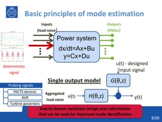
  • 8. Basic principles of mode estimation Power system dx/dt=Ax+Bu y=Cx+Du Inputs (load noise) Outputs (PMUs) Deterministic signal Exactly known excitation brings new information that can be used for improved mode identification Probing signals FACTS devices AVR Turbine governors H(θ,z) G(θ,z) e(t) y(t) u(t) - designed input signal Aggregated load noise Single output model 8/28
  • 9.  Model structure of the power system o ARMAX o Box Jenkins Mathematical formulation  Optimization problem: min 𝜃 1 𝑁 𝑡=1 𝑁 𝜀 𝑡, 𝜃 2 𝜀(𝑡, 𝜃) = 𝑦(𝑡) − 𝑦 ⌢ (𝑡|𝑡 − 1 Solution - identified model ( , ) ( , ) ( ) ( ) ( ) ( , ) ( , ) B z C z y t u t e t A z D z       Contain information about the critical modes/poles 9/28
  • 10. Model order selection  Too low model order => bias of the estimate  Too high model order => large variance/inaccuracy Data length Time resolutionvs Methods:  Residual analysis  Singular value analysis  Akaike Information Criterion  Variance-Accounted-For 10/28
  • 11. Outline 1 • Oscillations – ambient excitation, modes 2 • Principles of mode estimation 3 • Optimal probing design and signal selection 4 • Mode estimation with non-white loads 5 • Prototype implementation 6 • Conclusions 11/28
  • 12. Optimal probing – problem formulation  Objective: Identify the critical damping ratio of G(z)                                        1 * * 0 0 0 02 1 ( , ) ( , ) ( , ) ( , ) 2 2 ( )u euu e N N P F F d F F d H(θ,z) G(θ,z) e(t) y(t) u(t) - input signal load measurement How should the probing signal look like ? 12/28 Spectrum influences accuracy  1 P Good estimate  1 P Bad estimate  ( )u  ( )u There is a limit how strong probing can be Stronger probing provides better accuracy
  • 13. Spectrum calculation of the probing signal 1) Control effort 2) System disturbance 3) Accuracy Objective function                                2 1 2 (t) min ( ) (s) ( ) 2 2u uu k k J d G d Constraint: var( ) T i i i e P e r    r - tolerance Input power Output power (frequency deviation)  Requirements : Optimization problem in a form of LMI The solution is the power spectrum of the probing signal 14/28
  • 14. Time domain probing signal realization  Spectrum calculation (solved)  Time domain signal realization LMI Signal realization max var(ζ) Multisine ACF (rd) min(upeak 2 /urms 2 ) FIR filter min(║ r-rd║2 ) white noise - e(t) u(t) u(t) u(t) Probing Φu(ω) calculation 13/28
  • 15. A method for probing signal realization  Power spectrum      ( ) ( ) m j r u des r m ACF r e 1 1 ( ) ( ) ( ) k k i ACF u i u i k          2 ( ) 0 ( ) ( ) M K k des u k min ACF ACF        Sample autocorrelation  Optimization  Efficient recursive algorithm 15/28 Aimed probing autocorrelation General expression for autocorrelation Time domain signal as the decision variable
  • 16. Optimal probing signal design results 0 0.5 1 1.5 2 2.5 0 5000 10000 15000 Frequency [Hz] Powerspectrum 0 0.5 1 1.5 2 2.5 0 1 2 3 4 x 10 5 Frequency [Hz] Powerspectrum Input spectrum parameterization White noise Multi-sine FIR filter var{u(t)} 10410.0 1441.58 1933.55 var{y(t)} 1.6761 1.598 1.5515 var{uy(t)} 6881.10 2318.81 2518.24 The same accuracy obtained with the 5-7 times weaker excitation The same input power provides 4-5 times better accuracy (0.25*10-5) Damping variance < 10-5 Benefits of the proposed method 16/28 KTH Nordic 32 Minimized input power Minimized disturbance2 critical modes 0.5Hz & 0.76Hz Reactive power probing
  • 17. Optimal signal selection for mode estimation  Only a few signals are sufficient for accurate estimation  Large number of signals introduce bias and extensive computational effort  Variance of the estimate describes estimation quality Compute asymptotic variance for each measured signal Rank the signals Select the top ones                                         1 * * 0 0 0 02 1 ( , ) ( , ) ( , ) ( , ) ( ) 2 2e e u u u N N P F F d F F d                     1 * 0 0 ( , ) ( , ) 2 e e N P F F d 17/28
  • 18. 49 48 50 17 40 31 18 42 44 47 0.09 0.1 0.11 0.12 0.13 0.14 0.15 1 2 3 4 5 6 7 8 9 10 Voltage angles 37 26 36 32 34 39 38 43 22 21 0.15 0.16 0.17 0.18 0.19 0.2 0.21 0.22 0.23 1 2 3 4 5 6 7 8 9 10 Voltage magnitudes Optimal signal selection results 18/28
  • 19. Outline 1 • Oscillations – ambient excitation, modes 2 • Principles of mode estimation 3 • Optimal probing design and signal selection 4 • Mode estimation with non-white loads 5 • Prototype implementation 6 • Conclusions 19/28
  • 20. Ambient mode estimation with non-white loads - Approach 20  Transmission/distribution border points have PMUs  Non-white loads are inputs  Input-output identification Source: EirGrid plc Transmission Distribution 20/28 Non-white noise excitation corrupts results of the classical mode estimators
  • 21. Mode estimation considering spectral characteristics of load  Direct closed loop identification  Only modes of the transmission parts are identified 0 0.5 1 1.5 2 0.495 0.497 0.499 0.501 0.503 0.505  ModeFrequency[Hz] 0 0.5 1 1.5 2 2.5 3 0.495 0.497 0.499 0.501 0.503 0.505 0 0.5 1 1.5 2 1 1.8 2.6 3.4 4.2 5 0 0.5 1 1.5 2 2.5 3 1 1.8 2.6 3.4 4.2 5 Kpf ModeDamping[%] Mode frequency vs  Mode frequency vs Kpf Mode damping vs  Mode damping vs Kpf 𝑃𝐿 = 𝑃0 𝑉 𝑉0 𝛼 (1 + 𝐾 𝑝𝑓 𝛥𝑓) Transmission Load Power State (V,θ) Loads Independent disturbance (white noise) 21/28  Load effects are compensated afterwards
  • 22. Results – Presence of forced oscillations 0 20 40 60 80 100 0 0.2 0.4 0.6 0.8 1 1.2 Damping ratio [%] Frequency[Hz] Estimated modes Real system modes 0 20 40 60 80 100 0 0.2 0.4 0.6 0.8 1 1.2 Damping ratio [%] Frequency[Hz] Estimated modes Real system modes Yule-Walker method Forced oscillation (0.45 Hz) 0 20 40 60 80 100 0 0.2 0.4 0.6 0.8 1 1.2 Damping ratio [%] Frequency[Hz] Estimated modes Real system modes N4SID method  KTH Nordic32 system with forced oscillation at 0.45 Hz  Monte Carlo simulations (large number of mode estimations)  Classical methods: – Forced oscillation estimated as a critical mode – Real system mode masked by the forced oscillation Classical methods Proposed method 22/28 Proposed method discerns the forced oscillation
  • 23. Results – white noise input  When all assumptions used in classical mode estimators are fully satisfied  All methods provide similar results 0 20 40 60 80 100 0 0.2 0.4 0.6 0.8 1 1.2 Damping ratio [%] Frequency[Hz] Estimated modes Real system modes 0 20 40 60 80 100 0 0.2 0.4 0.6 0.8 1 1.2 Damping ratio [%] Frequency[Hz] Estimated modes Real system modes 0 20 40 60 80 100 0 0.2 0.4 0.6 0.8 1 1.2 Damping ratio [%] Frequency[Hz] Estimated modes Real system modes Classical methods Yule-Walker method N4SID method Parameters Yule- Walker N4SID Proposed Method Mode1 Mean {f} [Hz] 0.4972 0.4978 0.4966 Mean {} [%] 3.3081 4.1213 3.8104 Var {f} 8.8670e-6 1.6260e-5 1.6592e-5 Var {} 0.2728 0.7942 0.8561 Mode2 Mean {f} [Hz] 0.7334 0.7309 0.7386 Mean {} [%] 3.8184 4.7095 3.5497 Var {f} 1.4072e-5 6.2711e-5 2.3151e-5 Var{} 0.3563 1.7925 0.5965 Proposed method 23/28
  • 24. Outline 1 • Oscillations – ambient excitation, modes 2 • Principles of mode estimation 3 • Optimal probing design and signal selection 4 • Mode estimation with non-white loads 5 • Prototype implementation 6 • Conclusions 24/28
  • 25.  Power system or real-time simulator  Phasor measurement units (PMUs).  Phasor data concentrator (PDC) SDK PMU 1 PMU 2 PMU n PDC Comm. Network IEEE C37.118 Protocol KTH SmarTS Lab Wide Area Measurements System Real system Real time simulator User application Source Measurements Comm. Infrastructure Decoder  Communication Network  Software Development Kit (SDK)  User applications 25/28
  • 26. Prototype mode estimation application  LabVIEW platform  Real-life data  The critical mode 0.39 Hz damping ratio 9 % (average)  Other modes are observable at 0.2 Hz, 1 Hz and 1.4 Hz  0.5 Hz mode sporadically appears as a poorly damped mode 26/28
  • 27. Conclusions  A comprehensive way of dealing with mode estimation uncertainty.  Probing when carefully designed provides a good mode estimation accuracy at low cost.  Some signals provide better mode estimates than others. Quality signal criterion is proposed.  A method that eliminates negative effects of non-white ambient excitation is proposed.  Testing of the mode estimation tools needs to include other components of the system. 27/28