


![Connections in structural style
By position association
module C_2_4_decoder_with_enable (A, E_n, D);
C_4_16_decoder_with_enable DX (X[3:2], W_n, word);
A = X[3:2], E_n = W_n, D = word
By name association
module C_2_4_decoder_with_enable (A, E_n, D);
C_2_4_decoder_with_enable DX (.E_n(W_n),
.A(X[3:2]), .D(word));
A = X[3:2], E_n = W_n, D = word](https://image.slidesharecdn.com/verilogpresentationfinal-150508114923-lva1-app6892/85/Verilog-presentation-final-15-320.jpg)


![Net Examples
wire x;
wire x, y;
wire [15:0] data, address;
wire vectored [1:7] control;
wire address = offset + index;
wor interrupt_1, interrupt_2;
tri [31:0] data_bus, operand_bus;
Value implicitly assigned by connection to primitive or
module output](https://image.slidesharecdn.com/verilogpresentationfinal-150508114923-lva1-app6892/85/Verilog-presentation-final-20-320.jpg)

![Register Examples
reg a, b, c;
reg [15:0] counter, shift_reg;
reg [8:4] flops;
integer sum, difference](https://image.slidesharecdn.com/verilogpresentationfinal-150508114923-lva1-app6892/85/Verilog-presentation-final-23-320.jpg)
![Constants (Parameters)
Declaration of parameters
parameter A = 2’b00, B = 2’b01, C = 2’b10;
parameter regsize = 8;
reg [regsize - 1:0]; /* illustrates use of parameter regsize */](https://image.slidesharecdn.com/verilogpresentationfinal-150508114923-lva1-app6892/85/Verilog-presentation-final-24-320.jpg)


![Transmitter
module transmitter (clk,ready,datain,dataout);
input clk,ready;
input [7:0] datain;
output reg dataout;
integer count=0;
reg q;
always@(posedge clk)
begin
if(ready==1) begin
q=1;
end
if(q==1)
begin
count=count+1;
if(count==1)
dataout=0;
if (count==2)
dataout=datain[0];
if(count==3)
dataout=datain[1];
if(count==4)
dataout=datain[2];
if(count==5)
dataout=datain[3];
if(count==6)
dataout=datain[4];
if(count==7)
dataout=datain[5];
if(count==8)
dataout=datain[6];
if(count==9)
dataout=datain[7];
if (count==10)
dataout=1;
if (count==11)
begin
q=0;
count=0;
end](https://image.slidesharecdn.com/verilogpresentationfinal-150508114923-lva1-app6892/85/Verilog-presentation-final-29-320.jpg)

![Receiver
module
ps2_keyboard(ps2_clk,ps2_data
,ps2_dataout);
input ps2_clk,ps2_data;
output reg [7:0] ps2_dataout;
integer count=0;
integer q=0;
reg [7:0] store;
reg parity;
always@(negedge ps2_clk)
begin
if (q==0) begin
if(ps2_data==0)
q=1;
end
else if (q==1) begin
if(count<8) begin
store[count]=ps2_data;
end
count=count+1;
if(count==8)
begin
if(ps2_data==(^store))
parity=1;
end
else if (count==9) begin
if(ps2_data==1 &&
parity==1)begin
ps2_dataout[0]=store[0];
ps2_dataout[1]=store[1];
ps2_dataout[2]=store[2];
ps2_dataout[3]=store[3];
ps2_dataout[4]=store[4];](https://image.slidesharecdn.com/verilogpresentationfinal-150508114923-lva1-app6892/85/Verilog-presentation-final-31-320.jpg)
![ps2_dataout[5]=store[5];
ps2_dataout[6]=store[6];
ps2_dataout[7]=store[7];
end
q=0;
parity=0;
count=0;
end
end
end
endmodule](https://image.slidesharecdn.com/verilogpresentationfinal-150508114923-lva1-app6892/85/Verilog-presentation-final-32-320.jpg)

![Top UART
module top_uart (clk,datain,dataout,p1);
input clk,datain;
output [7:0] p1;
output dataout;
wire b_clk,ready;
wire [7:0] r_dataout ;
BDG_clk c1( clk,b_clk);
ps2_keyboard r1(b_clk,datain,r_dataout);
transmitter t1(b_clk,ready,r_dataout,dataout);
assign p1=r_dataout;
endmodule](https://image.slidesharecdn.com/verilogpresentationfinal-150508114923-lva1-app6892/85/Verilog-presentation-final-34-320.jpg)


Verilog presentation final
- 2. Tevatron technologies Pvt. Ltd. (A registered private limited company under Ministry of Corporate Affairs, Govt. of India) is a Design and Product Company focused on VLSI Design, FPGA Based Design & Embedded Systems and nurturing the ecosystem for the same. It has branches in Lucknow ,Noida and Bangalore.
- 3. What is verilog ? Verilog is one of the two major Hardware Description Languages(HDL) used by hardware designers in industry and academia. VHDL is another one Verilog is easier to learn and use than VHDL Verilog is C-like . VHDL is very Aad-like. Verilog HDL allows a hardware designer to describer designs at a high level of abstraction such as at the architectural or behavioral level as well as the lower implementation levels(i.e., gate and switch levels).
- 4. Why use verilog ? Digital system are highly complex. Verilog language provides the digital designer, a software platform. Verilog allow user to express their design with BEHAVIORAL CONSTRUCTS. A program tool can convert the verilog program to a description that was used to make exact chip, like VLSI.
- 5. Development of verilog Verilog was introduced in 1985 by Gateway Design System Corporation, now a part of Cadence Design Systems. Until May, 1990, with the formation of Open Verilog International (OVI), Verilog HDL was a proprietary language of Cadence. Cadence was motivated to open the language to the Public Domain with the expectation that the market for Verilog HDL-related software products would grow more rapidly with broader acceptance of the language
- 6. Comparison b/w verilog and VHDL
- 7. Different styles of modelling Structural - instantiation of primitives and modules RTL/Dataflow - continuous assignments Behavioral - procedural assignments
- 8. MUX in structural style
- 10. MUX in behavioural style
- 11. Program structure Structure module <module name> (< port list>); < declares> <module items> endmodule . Module name an identifier that uniquely names the module. . Port list a list of input, inout and output ports which are used to other modules.
- 12. Program structure Declares section specifies data objects as registers, memories and wires as well as procedural constructs such as functions and tasks. . Module items initial constructs always constructs assignment End module
- 13. An example module Fulladder ( a,b,cin,sum,carry); input a,b,cin; output reg sum; output reg carry; always@(a,b,cin) begin if(a==0 && b==0 && cin==0) begin sum=0; carry=0; end else if (a==0 && b==0 && cin==1) begin sum=1; carry=0; end else if (a==0 && b==1 && cin==0) begin sum=1; carry=0; end
- 14. else if(a==0 && b==1 && cin==1) begin sum=0; carry=1; end else if (a==1 && b==0 && cin==0) begin sum=1; carry=0; end else if (a==1 && b==0 && cin==1) begin sum=0; carry=1; end else if (a==1 && b==1 && cin==0) begin sum=1; carry=0; end else if(a==1 && b==1 && cin==1) begin sum=1; carry=1;
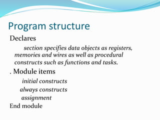
- 15. Connections in structural style By position association module C_2_4_decoder_with_enable (A, E_n, D); C_4_16_decoder_with_enable DX (X[3:2], W_n, word); A = X[3:2], E_n = W_n, D = word By name association module C_2_4_decoder_with_enable (A, E_n, D); C_2_4_decoder_with_enable DX (.E_n(W_n), .A(X[3:2]), .D(word)); A = X[3:2], E_n = W_n, D = word
- 16. Language convention Case-sensitivity Verilog is case-sensitive. Some simulators are case-insensitive Advice: - Don’t use case-sensitive feature! Keywords are lower case Different names must be used for different items within the same scope Identifier alphabet: Upper and lower case alphabetical decimal digits underscore
- 17. Language convention Maximum of 1024 characters in identifier First character not a digit Statement terminated by ; Free format within statement except for within quotes Strings enclosed in double quotes and must be on a single line Comments: All characters after // in a line are treated as a comment Multi-line comments begin with /* and end with */ Compiler directives begin with // synopsys Built-in system tasks or functions begin with $
- 18. variables Nets Used for structural connectivity Registers Abstraction of storage (May or may not be real physical storage) Properties of Both Informally called signals May be either scalar (one bit) or vector (multiple bits)
- 19. Data Types - Nets - Semantics wire - connectivity only; no logical tri - same as wire, but indicates will be 3- stated in hardware wand - multiple drivers - wired and wor - multiple drivers - wired or triand - same as wand, but 3-state trior - same as wor but 3-state supply0 - Global net GND supply1 - Global Net VCC (VDD) tri0, tri1, trireg
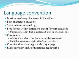
- 20. Net Examples wire x; wire x, y; wire [15:0] data, address; wire vectored [1:7] control; wire address = offset + index; wor interrupt_1, interrupt_2; tri [31:0] data_bus, operand_bus; Value implicitly assigned by connection to primitive or module output
- 21. Data Types - Register Semantics reg - stores a logic value integer – stores values which are not to be stored in hardware Defaults to simulation computer register length or 32 bits whichever is larger No ranges or arrays supported May yield excess hardware if value needs to be stored in hardware; in such a case, use sized reg. time - stores time 64-bit unsigned real - stores values as real num realtime - stores time values as real numbers
- 22. Register Assignment A register may be assigned value only within: a procedural statement a user-defined sequential primitive a task, or a function. A reg object may never by assigned value by: a primitive gate output or a continuous assignment
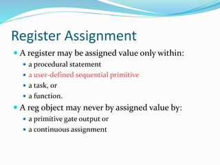
- 23. Register Examples reg a, b, c; reg [15:0] counter, shift_reg; reg [8:4] flops; integer sum, difference
- 24. Constants (Parameters) Declaration of parameters parameter A = 2’b00, B = 2’b01, C = 2’b10; parameter regsize = 8; reg [regsize - 1:0]; /* illustrates use of parameter regsize */
- 25. Operators Arithmetic (binary: +, -,*,/,%*); (unary: +, -) Bitwise (~, &,|,^,~^,^~) Reduction (&,~&,|,~|,^,~^,^~) Logical (!,&&,||,==,!=,===,!==) Relational (<,<=,>,>=) Shift (>>,<<) Conditional ? : Concatenation and Replications {A,B} {4{B}} * Not supported for variables
- 26. Project:UART UART: Universal asynchronous Receiver transmitter Its a piece of Computer hardware that translates between parallel and serial forms. • A UART may be used when: – High speed is not required – A cheap communication line between two devices is required
- 27. Use of UART PC serial port is a UART! Serializes data to be sent over serial cable – De-serializes received data Communication between distant computers – Serializes data to be sent to modem – De-serializes data received from modem Used to be commonly used for internet access Used to be used for mainframe access – A mainframe could have dozens of serial ports
- 28. Parts of UART Transmitter Receiver Baud generator( clock generator)
- 29. Transmitter module transmitter (clk,ready,datain,dataout); input clk,ready; input [7:0] datain; output reg dataout; integer count=0; reg q; always@(posedge clk) begin if(ready==1) begin q=1; end if(q==1) begin count=count+1; if(count==1) dataout=0; if (count==2) dataout=datain[0]; if(count==3) dataout=datain[1]; if(count==4) dataout=datain[2]; if(count==5) dataout=datain[3]; if(count==6) dataout=datain[4]; if(count==7) dataout=datain[5]; if(count==8) dataout=datain[6]; if(count==9) dataout=datain[7]; if (count==10) dataout=1; if (count==11) begin q=0; count=0; end
- 31. Receiver module ps2_keyboard(ps2_clk,ps2_data ,ps2_dataout); input ps2_clk,ps2_data; output reg [7:0] ps2_dataout; integer count=0; integer q=0; reg [7:0] store; reg parity; always@(negedge ps2_clk) begin if (q==0) begin if(ps2_data==0) q=1; end else if (q==1) begin if(count<8) begin store[count]=ps2_data; end count=count+1; if(count==8) begin if(ps2_data==(^store)) parity=1; end else if (count==9) begin if(ps2_data==1 && parity==1)begin ps2_dataout[0]=store[0]; ps2_dataout[1]=store[1]; ps2_dataout[2]=store[2]; ps2_dataout[3]=store[3]; ps2_dataout[4]=store[4];
- 33. Baud generator module BDG_clk (clk,clk_t); input clk; output reg clk_t; parameter baudrate=9600,b_clk=96000; integer i=0,divisor; always@(posedge clk) begin i = i + 1; divisor = (b_clk/baudrate); if(i== divisor/2) clk_t=0; //else if(i>divisor/2) else if (i == divisor)begin i = 0; clk_t=1; end end endmodule
- 34. Top UART module top_uart (clk,datain,dataout,p1); input clk,datain; output [7:0] p1; output dataout; wire b_clk,ready; wire [7:0] r_dataout ; BDG_clk c1( clk,b_clk); ps2_keyboard r1(b_clk,datain,r_dataout); transmitter t1(b_clk,ready,r_dataout,dataout); assign p1=r_dataout; endmodule
- 35. Video of the project