SlideShare a Scribd company logo
VLSI-GATE LEVEL DESIGN
-BY N.C.CHANDU PRASANTH
General Logic Circuit
General Logic Circuit:
CMOS STATIC LOGIC
Vlsi gate level design
CMOS INVERTER
WORKING OF CMOS INVERTER
Explanation of Working Operation
CMOS NOR GATE
Working of CMOS NOR Gate
CMOS NAND GATE
Working of CMOS NAND Gate
Complex Gates in CMOS Logic
AOI Logic Function(or) Design of XOR
Gate Using CMOS Logic
CMOS Implementation
Steps for CMOS Implementation
Vlsi gate level design
OAI Logic Function(or) Design of
XNOR Gate Using CMOS Logic
CMOS Implementation
Switch Logic
Pass Transistor
Vlsi gate level design
Advantages &Disadvantages of Pass
Transistor
Pass Transistor Logic(PTL)
• Only N_MOS Transistors are Used to design the logic.
• Input Signals are Applied to both Gate and
Drain/Source.
When A=1 Upper NMOS is ON, So
o/p is F=B
When A=0 Upper
NMOS is ON, So o/p is F=B
CMOS Transmission Gate
 Actually, It is a Parallel Connection of
N_MOSFET and P-MOSFET that realizes a
simple switch.
 Inputs to the gates of N-MOSFET and P-
MOSFET are Complementary to each other.
Working of CMOS Transmission Gate
Case-1
When C=1 and C^=0
Both NMOS&PMOS--------ON
 Nodes A&B-----------Short Circuited
Input Logic is Transferred to Output
Case-2
When C=10and C^=1
Both NMOS&PMOS--------OFF
 Nodes A&B-----------Open Circuited
Actually ,this is Called High-Impedance State.
Transmission Gate Symbol
Operation of Transmission Gate
Advantages &Disadvantages of
Transmission Gate
2- input Multiplexer using CMOS
Transmission Gates
Working
Alternative Gate Circuits
ALTERNATIVE GATE CIRCUITS
1. Pseudo- NMOS logic
2. Dynamic CMOS logic
(Pseudo –NMOS+NMOS Transistor)
3. Clocked CMOS (C2MOS) logic
4. CMOS domino logic
(Dynamic CMOS + Inveter)
5. n-p CMOS logic
General form of Pseudo- NMOS logic
G
Description
 It is used as a supplement for the CMOS logic circuits.
 In the pseudo-NMOS logic, the PUN is realized by a
single PMOS transistor.
The gate terminal of the PMOS transistor is connected
to the ground.
P-MOS Transistor remains permanently in the ON state
Depending on the input combinations, output goes low
through the PDN.
Only the NMOS logic (Qn) is driven by the input
Voltage
Qp acts as an active load for Qn.
Except for the load device(P-MOS), the Pseudo-NMOS
gate circuit is identical to the pull-down
network(PDN) of the CMOS gate.
Realization of logic circuits using Pseudo-NMOS logic
Advantages & Disadvantages of Pseudo N-MOS Logic
Advantages:
1) Uses less number of transistors as compared to
CMOS logic.
2) Geometrical area and delay gets reduced as it
requires less transistors.
3) Low power dissipation.
Disadvantages
1.The main drawback of using a Pseudo NMOS gate
instead of a CMOS gate is that the always on PMOS
load conducts a steady current when the output
voltage is lower than VDD.
2.Layout problems are critical.
General form of Dynamic CMOS logic
Description
 It is one of the alternate method of reducing
Transistor Count.
It is similar to Pseudo –NMOS Logic except one
additional NMOS Transistor(MN) Connected between
PDN and Ground.
PMOS Transistor in PUN and additional NMOS
Transistor(MN) in PDN are Operated by a Clock Signal
ϕ.
Dynamic Logic Circuit Operates in 2 Phases of Single
Clock Pulse ϕ
Phase-1 (Pre-Charge Phase ϕ =0)
Here, Output is Pre Charged to Logic High Level.
Phase-2 (Evaluation Phase ϕ=1)
Here, Output is evaluated based on applied Input Logic.
Dynamic CMOS Logic Example
Disadvantages of Dynamic CMOS logic
Dynamic CMOS Circuit has a Serious Problem
When they are cascaded.
Advantages of Dynamic CMOS logic
General form of CMOS Domino Logic
(Dynamic Logic + Inverter)
ϕ
Description
 It is a Slightly modified Version of Dynamic CMOS
Logic Circuit.
A Static Inverter is Connected at the Output of
each dynamic CMOS logic blocks.
Addition of Inverter Solves the Problem of
Cascading of dynamic CMOS logic Circuits.
 It is Suitable for only Non-Inverting Logic(the
expression having no complement over whole
expression)
For Inverting the logic the expression must be
reorganized before it can be realized using
Domino CMOS Logic.
Working
Case -1 when ϕ = 0
Output is Pre charged to logic high and O/P of static
Inverter is Low.
Case -2 When ϕ =1
O/P is either 0 (or) 1 Output of static Inverter
can make 0 1 in Evaluation. So, Irrespective of I/P
and O/p of Static Inverter can’t make 1 0 in
Evaluation Phase.
Note:
For, N- Input Logic function we require,
2N Transistors-- Static CMOS
N+2 Transistors- Dynamic CMOS
N+2+2 Transistors Domino CMOS
Example of Domino CMOS Logic
Clocked CMOS (C2MOS) logic
Description
A pull-up p-block and a complementary n-block pull-
down structure represent p and n-transistors
However, the logic in this case is connected to the
output only during the ON period of the clock.
Working
When ø = 1 the circuit acts an inverter , because
transistors Q3 and Q4 are ‘ON’ .
 It is said to be in the “Evaluation mode”. Therefore
the output Z changes its Previous value.
When ø = 0 the circuit is in hold mode, because
transistors Q3 and Q4 ‘OFF’ .
It is said to be in the “Pre Charge mode”. Therefore
the output Z remains its previous value.
n-p CMOS logic (NORA)
Description
In this, logic the actual logic blocks are
alternatively ‘n’ and ‘p’ in a cascaded structure.
The clock ø and ø^ are used alternatively to fed
the Pre Charge and Evaluate transistors.
Disadvantages of N-P CMOS Logic
Here, the P-tree blocks are slower than the
N-tree modules, due to the lower current drive
of the PMOS transistors in the logic network.

More Related Content

What's hot (20)

PPTX
NYQUIST CRITERION FOR ZERO ISI
FAIZAN SHAFI
 
PPT
Correlative level coding
srkrishna341
 
PDF
Mos transistor
Murali Rai
 
PDF
Design of IIR filters
op205
 
PPTX
Programmable logic devices
ISMT College
 
PPTX
Multiplexers
DrSonali Vyas
 
PPTX
Amplitude shift keying
Sunny Kumar
 
PPTX
Delta modulation
mpsrekha83
 
PPTX
M ary psk modulation
Ahmed Diaa
 
PDF
CMOS Topic 5 -_cmos_inverter
Ikhwan_Fakrudin
 
PPSX
VLSI Testing Techniques
Dr. A. B. Shinde
 
PPT
Source coding
Shankar Gangaju
 
PPT
Switch level modeling
Devi Pradeep Podugu
 
PPTX
FM demodulation using PLL
mpsrekha83
 
PPT
DOMINO LOGIC CIRCUIT (VLSI)
AmiBokasoda
 
PPTX
BiCMOS Technology
Mithileysh Sathiyanarayanan
 
PPT
Convolutional Codes And Their Decoding
Kakali Saharia
 
PPTX
Digital electronics logic families
BLESSINAR0
 
NYQUIST CRITERION FOR ZERO ISI
FAIZAN SHAFI
 
Correlative level coding
srkrishna341
 
Mos transistor
Murali Rai
 
Design of IIR filters
op205
 
Programmable logic devices
ISMT College
 
Multiplexers
DrSonali Vyas
 
Amplitude shift keying
Sunny Kumar
 
Delta modulation
mpsrekha83
 
M ary psk modulation
Ahmed Diaa
 
CMOS Topic 5 -_cmos_inverter
Ikhwan_Fakrudin
 
VLSI Testing Techniques
Dr. A. B. Shinde
 
Source coding
Shankar Gangaju
 
Switch level modeling
Devi Pradeep Podugu
 
FM demodulation using PLL
mpsrekha83
 
DOMINO LOGIC CIRCUIT (VLSI)
AmiBokasoda
 
BiCMOS Technology
Mithileysh Sathiyanarayanan
 
Convolutional Codes And Their Decoding
Kakali Saharia
 
Digital electronics logic families
BLESSINAR0
 

Similar to Vlsi gate level design (20)

PPTX
CMOS LOGIC STRUCTURES
VaishaliVaishali14
 
PPT
ppt.ppt on didgital logic design by muskan.s
muskans14
 
PDF
PERFORMANCE OF DIFFERENT CMOS LOGIC STYLES FOR LOW POWER AND HIGH SPEED
VLSICS Design
 
PPT
Combinational Logic
Sirat Mahmood
 
PPTX
cmoshssd-220105164535.pptx
KethavathVenkatesh3
 
PDF
BEC602-Module-4-Notes.pdf.Vlsi design and testing notes
VarshithaP6
 
PPTX
Combinational MOS Logic Design (Combinational Metal oxide semiconductor logic...
AmitKumar571646
 
PDF
cmoslogic_data7.pdf
kalivaraprasad2
 
PPTX
CMOS Logic
Sudhanshu Janwadkar
 
PPT
Dynamic CMOS and Domino logic design .ppt
BEVARAVASUDEVAAP1813
 
PPTX
CO-3 Part-2 combinational logic vlsi design
LakshmiJagupilla
 
PPT
UNIT-4-Logic styles for low power_part_2.ppt
Ravi Selvaraj
 
PDF
9_DVD_Dynamic_logic_circuits.pdf
Usha Mehta
 
DOC
LECTURE NOTES-DSD1.doc
Sai Venu
 
PPTX
CMOS
AWANISHKUMAR84
 
PDF
IC_Lectures_Updated.pdf
AbdelazizmohammedZay
 
PPTX
UNIT 3_new_2025onwardsvhshdhdhhdhdhdhhdhdhhdhd.pptx
mickname134
 
PPTX
Module-3 Basic digital and analog circuits.pptx
BEVARAVASUDEVAAP1813
 
PPTX
Combinational Logic Circuits (1).pptx
ramkumarraja7
 
PPTX
NMOS PPT for 2nd year
faltuthings
 
CMOS LOGIC STRUCTURES
VaishaliVaishali14
 
ppt.ppt on didgital logic design by muskan.s
muskans14
 
PERFORMANCE OF DIFFERENT CMOS LOGIC STYLES FOR LOW POWER AND HIGH SPEED
VLSICS Design
 
Combinational Logic
Sirat Mahmood
 
cmoshssd-220105164535.pptx
KethavathVenkatesh3
 
BEC602-Module-4-Notes.pdf.Vlsi design and testing notes
VarshithaP6
 
Combinational MOS Logic Design (Combinational Metal oxide semiconductor logic...
AmitKumar571646
 
cmoslogic_data7.pdf
kalivaraprasad2
 
Dynamic CMOS and Domino logic design .ppt
BEVARAVASUDEVAAP1813
 
CO-3 Part-2 combinational logic vlsi design
LakshmiJagupilla
 
UNIT-4-Logic styles for low power_part_2.ppt
Ravi Selvaraj
 
9_DVD_Dynamic_logic_circuits.pdf
Usha Mehta
 
LECTURE NOTES-DSD1.doc
Sai Venu
 
IC_Lectures_Updated.pdf
AbdelazizmohammedZay
 
UNIT 3_new_2025onwardsvhshdhdhhdhdhdhhdhdhhdhd.pptx
mickname134
 
Module-3 Basic digital and analog circuits.pptx
BEVARAVASUDEVAAP1813
 
Combinational Logic Circuits (1).pptx
ramkumarraja7
 
NMOS PPT for 2nd year
faltuthings
 
Ad

Recently uploaded (20)

PDF
Ethics and Trustworthy AI in Healthcare – Governing Sensitive Data, Profiling...
AlqualsaDIResearchGr
 
PPTX
Arduino Based Gas Leakage Detector Project
CircuitDigest
 
PDF
ARC--BUILDING-UTILITIES-2-PART-2 (1).pdf
IzzyBaniquedBusto
 
DOCX
CS-802 (A) BDH Lab manual IPS Academy Indore
thegodhimself05
 
PPTX
Hashing Introduction , hash functions and techniques
sailajam21
 
PPTX
EC3551-Transmission lines Demo class .pptx
Mahalakshmiprasannag
 
PPTX
MPMC_Module-2 xxxxxxxxxxxxxxxxxxxxx.pptx
ShivanshVaidya5
 
PDF
GTU Civil Engineering All Semester Syllabus.pdf
Vimal Bhojani
 
PPTX
Introduction to Design of Machine Elements
PradeepKumarS27
 
PDF
Zilliz Cloud Demo for performance and scale
Zilliz
 
PPTX
Pharmaceuticals and fine chemicals.pptxx
jaypa242004
 
PDF
6th International Conference on Machine Learning Techniques and Data Science ...
ijistjournal
 
PDF
Book.pdf01_Intro.ppt algorithm for preperation stu used
archu26
 
DOC
MRRS Strength and Durability of Concrete
CivilMythili
 
PPTX
Introduction to Neural Networks and Perceptron Learning Algorithm.pptx
Kayalvizhi A
 
DOCX
8th International Conference on Electrical Engineering (ELEN 2025)
elelijjournal653
 
PDF
Design Thinking basics for Engineers.pdf
CMR University
 
PPTX
The Role of Information Technology in Environmental Protectio....pptx
nallamillisriram
 
PPTX
Day2 B2 Best.pptx
helenjenefa1
 
PPTX
Solar Thermal Energy System Seminar.pptx
Gpc Purapuza
 
Ethics and Trustworthy AI in Healthcare – Governing Sensitive Data, Profiling...
AlqualsaDIResearchGr
 
Arduino Based Gas Leakage Detector Project
CircuitDigest
 
ARC--BUILDING-UTILITIES-2-PART-2 (1).pdf
IzzyBaniquedBusto
 
CS-802 (A) BDH Lab manual IPS Academy Indore
thegodhimself05
 
Hashing Introduction , hash functions and techniques
sailajam21
 
EC3551-Transmission lines Demo class .pptx
Mahalakshmiprasannag
 
MPMC_Module-2 xxxxxxxxxxxxxxxxxxxxx.pptx
ShivanshVaidya5
 
GTU Civil Engineering All Semester Syllabus.pdf
Vimal Bhojani
 
Introduction to Design of Machine Elements
PradeepKumarS27
 
Zilliz Cloud Demo for performance and scale
Zilliz
 
Pharmaceuticals and fine chemicals.pptxx
jaypa242004
 
6th International Conference on Machine Learning Techniques and Data Science ...
ijistjournal
 
Book.pdf01_Intro.ppt algorithm for preperation stu used
archu26
 
MRRS Strength and Durability of Concrete
CivilMythili
 
Introduction to Neural Networks and Perceptron Learning Algorithm.pptx
Kayalvizhi A
 
8th International Conference on Electrical Engineering (ELEN 2025)
elelijjournal653
 
Design Thinking basics for Engineers.pdf
CMR University
 
The Role of Information Technology in Environmental Protectio....pptx
nallamillisriram
 
Day2 B2 Best.pptx
helenjenefa1
 
Solar Thermal Energy System Seminar.pptx
Gpc Purapuza
 
Ad

Vlsi gate level design

  • 1. VLSI-GATE LEVEL DESIGN -BY N.C.CHANDU PRASANTH
  • 6. WORKING OF CMOS INVERTER
  • 9. Working of CMOS NOR Gate
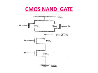
  • 11. Working of CMOS NAND Gate
  • 12. Complex Gates in CMOS Logic
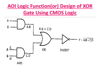
  • 13. AOI Logic Function(or) Design of XOR Gate Using CMOS Logic
  • 15. Steps for CMOS Implementation
  • 18. OAI Logic Function(or) Design of XNOR Gate Using CMOS Logic
  • 23. Advantages &Disadvantages of Pass Transistor
  • 24. Pass Transistor Logic(PTL) • Only N_MOS Transistors are Used to design the logic. • Input Signals are Applied to both Gate and Drain/Source. When A=1 Upper NMOS is ON, So o/p is F=B When A=0 Upper NMOS is ON, So o/p is F=B
  • 25. CMOS Transmission Gate  Actually, It is a Parallel Connection of N_MOSFET and P-MOSFET that realizes a simple switch.  Inputs to the gates of N-MOSFET and P- MOSFET are Complementary to each other.
  • 26. Working of CMOS Transmission Gate Case-1 When C=1 and C^=0 Both NMOS&PMOS--------ON  Nodes A&B-----------Short Circuited Input Logic is Transferred to Output Case-2 When C=10and C^=1 Both NMOS&PMOS--------OFF  Nodes A&B-----------Open Circuited Actually ,this is Called High-Impedance State.
  • 30. 2- input Multiplexer using CMOS Transmission Gates
  • 32. ALTERNATIVE GATE CIRCUITS 1. Pseudo- NMOS logic 2. Dynamic CMOS logic (Pseudo –NMOS+NMOS Transistor) 3. Clocked CMOS (C2MOS) logic 4. CMOS domino logic (Dynamic CMOS + Inveter) 5. n-p CMOS logic
  • 33. General form of Pseudo- NMOS logic G
  • 34. Description  It is used as a supplement for the CMOS logic circuits.  In the pseudo-NMOS logic, the PUN is realized by a single PMOS transistor. The gate terminal of the PMOS transistor is connected to the ground. P-MOS Transistor remains permanently in the ON state Depending on the input combinations, output goes low through the PDN. Only the NMOS logic (Qn) is driven by the input Voltage Qp acts as an active load for Qn. Except for the load device(P-MOS), the Pseudo-NMOS gate circuit is identical to the pull-down network(PDN) of the CMOS gate.
  • 35. Realization of logic circuits using Pseudo-NMOS logic
  • 36. Advantages & Disadvantages of Pseudo N-MOS Logic Advantages: 1) Uses less number of transistors as compared to CMOS logic. 2) Geometrical area and delay gets reduced as it requires less transistors. 3) Low power dissipation. Disadvantages 1.The main drawback of using a Pseudo NMOS gate instead of a CMOS gate is that the always on PMOS load conducts a steady current when the output voltage is lower than VDD. 2.Layout problems are critical.
  • 37. General form of Dynamic CMOS logic
  • 38. Description  It is one of the alternate method of reducing Transistor Count. It is similar to Pseudo –NMOS Logic except one additional NMOS Transistor(MN) Connected between PDN and Ground. PMOS Transistor in PUN and additional NMOS Transistor(MN) in PDN are Operated by a Clock Signal ϕ. Dynamic Logic Circuit Operates in 2 Phases of Single Clock Pulse ϕ Phase-1 (Pre-Charge Phase ϕ =0) Here, Output is Pre Charged to Logic High Level. Phase-2 (Evaluation Phase ϕ=1) Here, Output is evaluated based on applied Input Logic.
  • 40. Disadvantages of Dynamic CMOS logic Dynamic CMOS Circuit has a Serious Problem When they are cascaded.
  • 41. Advantages of Dynamic CMOS logic
  • 42. General form of CMOS Domino Logic (Dynamic Logic + Inverter) ϕ
  • 43. Description  It is a Slightly modified Version of Dynamic CMOS Logic Circuit. A Static Inverter is Connected at the Output of each dynamic CMOS logic blocks. Addition of Inverter Solves the Problem of Cascading of dynamic CMOS logic Circuits.  It is Suitable for only Non-Inverting Logic(the expression having no complement over whole expression) For Inverting the logic the expression must be reorganized before it can be realized using Domino CMOS Logic.
  • 44. Working Case -1 when ϕ = 0 Output is Pre charged to logic high and O/P of static Inverter is Low. Case -2 When ϕ =1 O/P is either 0 (or) 1 Output of static Inverter can make 0 1 in Evaluation. So, Irrespective of I/P and O/p of Static Inverter can’t make 1 0 in Evaluation Phase. Note: For, N- Input Logic function we require, 2N Transistors-- Static CMOS N+2 Transistors- Dynamic CMOS N+2+2 Transistors Domino CMOS
  • 45. Example of Domino CMOS Logic
  • 47. Description A pull-up p-block and a complementary n-block pull- down structure represent p and n-transistors However, the logic in this case is connected to the output only during the ON period of the clock. Working When ø = 1 the circuit acts an inverter , because transistors Q3 and Q4 are ‘ON’ .  It is said to be in the “Evaluation mode”. Therefore the output Z changes its Previous value. When ø = 0 the circuit is in hold mode, because transistors Q3 and Q4 ‘OFF’ . It is said to be in the “Pre Charge mode”. Therefore the output Z remains its previous value.
  • 48. n-p CMOS logic (NORA)
  • 49. Description In this, logic the actual logic blocks are alternatively ‘n’ and ‘p’ in a cascaded structure. The clock ø and ø^ are used alternatively to fed the Pre Charge and Evaluate transistors.
  • 50. Disadvantages of N-P CMOS Logic Here, the P-tree blocks are slower than the N-tree modules, due to the lower current drive of the PMOS transistors in the logic network.