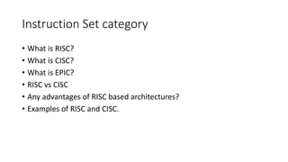
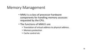
SlideShare a Scribd company logo
ARM PROCESSOR
Migrating from 8-/16-bit to 32 bit
• Data width
• n-bit ALU
• Arithmetic Operations
• Form factor
• Data types
• Speed and memory
Instruction Set category
• What is RISC?
• What is CISC?
• What is EPIC?
• RISC vs CISC
• Any advantages of RISC based architectures?
• Examples of RISC and CISC.
4
• What is an Embedded System?
Embedded System=Hardware + Software
Definition: It is a computational engine, employing hardware and
software, designed to perform specific function/s.
The software is used for providing features and flexibility.
The hardware is used for performance and sometimes security.
5
ARM Embedded Systems
• Key component of many 32 – bit embedded
systems
• Portable Consumer devices
• ARM1 prototype in 1985
• One of the ARM’s most successful cores is the
ARM7TDMI,provides high code density and low
power consumption.
6
The RISC Design Philosophy
• ARM Core uses a RISC architecture
• ARM licenses its cores out and other companies make processors
based on its cores
7
The RISC Design Philosophy
• RISC is characterized by limited number of instructions
• A complex instruction is obtained as a sequence of simple
instructions.so,in RISC processor software is complex but the
processor architecture is simple.
• Large number of registers are required.
• Pipelined instruction execution.
Ex : ARM, ATMEL AVR, MIPS, Power PC etc
8
The CISC Design Philosophy
• CISC is characterized by large instruction set.
• The aim of designing CISC processors is to reduce software complexity
by increasing the complexity of processor architecture.
• Very small number of registers are available.
Ex : Intel X86 family,Motorola 68000 series.
9
CISC vs. RISC
Compiler
Processor
Code Generation
Greater
Complexity
CISC
Compiler
Processor
Code Generation
Greater
Complexity
RISC
10
RISC – 4 major design rules
• Instructions
• Reduced Number of Instructions
• Execute in a single cycle
• The compiler synthesizes complicated operations
• Each instruction is a fixed length
11
RISC – 4 major design rules
• Pipelines
• The processing of instructions is broken down into smaller units that can be
executed in parallel by pipelines
• Pipeline advances by one step on each cycle for maximum throughput
12
RISC – 4 major design rules
• Registers
• Have a large general purpose register set
• Any register can contain either data or address
• CISC has dedicated registers for specific purposes.
13
RISC – 4 major design rules
• Load – Store Architecture
• Separate load and store instructions transfers data between the register bank
and external memory
14
The ARM Design Philosophy
• Reduce power consumption
• High code density
• Reduce the area of the die taken up by the embedded processor
• Incorporated hardware debug technology
15
Instruction set for Embedded Systems
• Variable cycle execution for certain instructions
• Inline barrel shifter leading to more complex instructions
• Thumb 16 – bit instructions
• Conditional execution
• Enhanced Instructions
16
ARM Processor Fundamentals
17
Agenda
• Registers
• CPSR
• Pipeline
• Exceptions, Interrupts and the Vector Table
• Core Extensions
• Architecture Revisions
• ARM Processor Families
• Summary
18
ARM core dataflow model
Incrementer
Address Register
ALU
Barrel Shifter
MAC
Register File
r0 – r15
Sign Extend
Instruction
Decoder
Read
Data
A B Acc
Rd
Result
B
A
r15
pc
Rn Rm
N
Address
19
ARM core dataflow model
• Functional units connected by data buses
• Data Bus  Data or Instruction
• Von Neumann architecture  Data and instruction share
the same bus
• Load Store Architecture
• Register File – 32 bit registers
• ARM instruction has 2 source and 1 destination register
• L/S inst: use the ALU to generate an address to be held in
the address reg. and broadcast on the Address Bus
• Result Bus
20
Registers – User Mode
r0
r1
r2
r3
r4
r5
r6
r7
r8
r9
r10
r11
r12
r13 sp
r14 lr
r15 pc
cpsr
-
• 32 bit in size
• Hold either data or address
• 16 data registers(r0 – r15) and 2 processor status
register (cpsr & spsr)
• r13, r14, r15 – Special functions
• r13 (sp) –stores the head of the stack in the current
processor mode
• r14 (lr) – the core puts the return address whenever it
calls a subroutine
• r15 (pc) – contains the address of the next instruction
to be fetched by the processor
• Which register are visible to the programmer depend
upon the current mode of the processor
21
Current Program Status Register
• To monitor and control internal operations
• Some ARM Processor core have extra bits
allocated
N Z C V I F T Mode
31 30 29 28 7 6 5 4 0
Condition Flags Processor Mode
Interrupt
Masks
Thumb State
Function
Bit
Fields
Flags Status Extension Control
22
Processor Modes
• Determines which registers are active and the
access rights to the cpsr register itself
• Privileged & Nonprivileged
• Abort
• Fast Interrupt Request
• Interrupt Request
• Supervisor
• System
• Undefined
• User
Privileged-R/W
access to CPSR
Nonprivileged-R Access to
CF,R/W access to
ConditionFlags
23
Processor Modes
• Abort – Failed attempt to access memory
• FIQ IRQ – Two interrupt levels available on the ARM
processor
• Supervisor – OS kernel operates
• System – Special version of user mode that allows full
R/W access to the cpsr
• Undefined – processor encounters an instruction that
is undefined
• User – used in programs & applications
• When a power is applied to the core it starts in
supervisor mode.
24
Banked Registers
r0
r1
r2
r3
r4
r5
r6
r7
r8
r9
r10
r11
r12
r13 sp
r14 lr
r15 pc
cpsr
-
r8_fiq
r9_fiq
r10_fiq
r11_fiq
r12_fiq
r13_fiq
r14_fiq
spsr_fiq
r13_irq
r14_irq
spsr_irq
r13_svc
r14_svc
spsr_svc
r13_undef
r14_undef
spsr_undef
r13_abt
r14_abt
spsr_abt
Fast
Interrupt
Request
Interrupt
Request Supervisor Undefined Abort
User &
System
Banked Registers
25
Banked Registers
• Banked registers are available only when the processor is in a
particular mode
• Every processor mode except user mode can change mode by
writing directly to the mode bits of the cpsr
• Banked registers are a subset of the main 16 registers
• If we change processor mode, a banked register from the
new mode will replace an existing register
• Exceptions and Interrupts cause a mode change
26
Changing mode on an exception
r0
r1
r2
r3
r4
r5
r6
r7
r8
r9
r10
r11
r12
r13 sp
r14 lr
r15 pc
cpsr
-
User Mode
r13_irq
r14_irq
spsr_irq
Interrupt
Request
Mode
• This change causes user
register r13 and r14 to be
banked
• The user registers are
replaced with registers
r13_irq and r14_irq
• spsr stores the previous
mode cpsr
27
Processor Mode
Mode Abbr: Privileged Mode[4:0]
Abort abt yes 10111
Fast Interrupt Request fiq yes 10001
Interrupt Request irq yes 10010
Supervisor svc yes 10011
System sys yes 11111
Undefined und yes 11011
User usr no 10000
cpsr is not copied into the spsr when a mode
change is forced due to a program writing directly
to the cpsr.
28
State and Instruction Sets
• There are three instruction sets
• ARM
• Thumb
• Jazelle
The Jazelle instruction set is a closed instruction set
and is not openly available.
To take advantage of Jazelle extra software has to
be licensed from both ARM Limited and Sun
Microsystems.
29
State and Instruction Sets
ARM
(cpsr T = 0)
Thumb
(cpsr T = 1)
Instruction Size 32 bit 16 bit
Core Instruction 58 30
Conditional Execution Most Only branch instructions
Data Processing Instructions Access to barrel shifter
and ALU
Separate barrel and ALU
instructions
Program Status Register R/W in privileged mode No direct access
Register Usage 15 GPR + PC 8 GPR + 7 high registers
+ PC
30
State and Instruction Sets
Jazelle
(cpsr T = 0, J = 1)
Instruction Size 8 bit
Core Instruction Over 60% of the java bytecodes are
implemented in hardware; the rest of the
codes are implemented in software
31
Interrupt Masks
• Are used to stop specific interrupt requests from
interrupting the processor
• IRQ
• FIQ
• The I bit masks IRQ when set to binary 1, and F bit
masks FIQ when set to binary 1
32
Condition Flags
Flag Flag Name Set when
Q Saturation The result causes an overflow and / or saturation
V oVerflow The result causes a signed overflow
C Carry The result causes an unsigned carry
Z Zero The result is zero, frequently used to indicate the
equality
N Negative Bit 31 of the result is a binary 1
33
Condition Flags
• Condition flags are updated by comparisons and the result of ALU
operations that specify the S instruction suffix
• If SUBS results in a register value of zero, then the Z flag in the cpsr is set
34
Condition Flags – Eg
0 0 1 0 0 1 0 10011
31 30 29 28 7 6 5 4 0
nzCvq svc
i F t
Function
Bit
Fields
Flags Status Extension Control
0
24
0
27
j
cpsr = nzCvqjiFt_SVC
35
Conditional Execution
• Conditional execution controls whether or not the core will
execute an instruction
• Most instructions have a condition attribute that
determines if the core will execute it based on the setting
of the condition flags
• Prior to execution, the processor compares the condition
attribute with the condition flags in the cpsr
• If they match, then the instruction is executed, otherwise
the instruction is ignored
• When a condition mnemonic is not present, the default
behaviour is set to always (AL) execute
36
Conditional Execution
Mnemonic Name Condition Flags
EQ equal Z
NE not equal z
CS HS carry set/unsigned higher or same C
CC LO carry clear/unsigned lower c
MI minus/negative N
PL plus/positive or zero n
VS overflow V
VC no overflow v
HI unsigned higher zC
LS unsigned lower or same Z or c
GE signed greater than or equal NV or nv
LT signed less than Nv or nV
GT signed greater than NzV or nzv
LE signed less than or equal Z or Nv or nV
AL always (unconditional) ignored
37
Pipeline
• Is a mechanism a RISC processor uses to execute instructions
• Using a pipeline speeds up execution by fetching the next instruction
while other instructions are being decoded and executed
38
ARM7 Three stage pipeline
• Fetch loads an instruction from memory
• Decode identifies the instruction to be executed
• Execute processes the instruction and writes the
result back to a register
Fetch Decode Execute
39
Pipelined instruction sequence
ADD
SUB ADD
CMP SUB ADD
Fetch Decode Execute
Cycle 1
Cycle 2
Cycle 3
Time
• Filling the pipeline
• Allows the core to execute an instruction every cycle
40
ARM9 Five stage pipeline
Fetch Decode Execute Memory Write
• Higher operating frequency  higher performance
• Latency increases
• Increase in instruction throughput by around 13%
in 5 stage pipeline
• 1.1 Dhrystone MIPS per MHz
41
ARM9 Five stage pipeline
• Fetch
• The instruction is fetched from memory and placed in the instruction pipeline
• Decode
• The instruction is decoded and register operands read from the register file
• Execute
• An operand is shifted and the ALU result generated
• Memory (Buffer/Data)
• Data memory is accessed if required. Otherwise the ALU result is buffered for
one clock cycle to give the same pipeline flow for all instructions
• Write (Write-Back)
• The results generated by the instruction are written back to the register file,
including any data loaded from memory
42
ARM10 Six stage pipeline
Fetch Decode Execute Memory Write
Issue
• Increase in instruction throughput by around 34%
in 6 stage pipeline
• 1.3 Dhrystone MIPS per MHz
• Code written for the ARM7 will execute on ARM9
and ARM10
43
ARM Instruction Sequence
MSR
ADD
AND
SUB
MSR
ADD
AND
MSR
ADD
cpsr
IFt_SVC
cpsr
IFt_SVC
cpsr
iFt_SVC
Fetch Decode Execute
Cycle 1
Cycle 2
Cycle 3
Time
Cycle 4
44
Pipeline Characteristics
• An instruction in the execute stage will complete even though an
interrupt has been raised
• The execution of a branch instruction or branching by the direct
modification of the PC causes the ARM core to flush its pipeline
45
Exceptions, Interrupts, and the Vector Table
• When an exception or interrupt occurs, the processor set
the PC to a specific memory address
• The address is within a special address range called the
vector table
• The entries in the vector table are instructions that
branch to specific routines designed to handle a
particular exception or interrupt
• When an exception or interrupt occurs,the processor
suspends normal execution and starts loading
instructions from the exception vector table.
46
Exceptions, Interrupts, and the Vector Table
Exception / Interrupt Shorthand Address High Address
Reset RESET 0x00000000 0xffff0000
Undefined Instruction UNDEF 0x00000004 0xffff0004
Software Interrupt SWI 0x00000008 0xffff0008
Prefetch Abort PABT 0x0000000C 0xffff000C
Data Abort DABT 0x000000010 0xffff0010
Reserved - 0x000000014 0xffff0014
Interrupt Request IRQ 0x000000018 0xffff0018
Fast Interrupt Request FIQ 0x00000001C 0xffff001C
47
Exceptions, Interrupts, and the Vector Table
• RESET – when power is applied, branches to initialization code
• UNDEF – when the processor cannot decode an instruction
• SWI – when a SWI instruction is called
• PABT – attempts to fetch an instruction from an address
without the correct access permissions
• DABT –attempts to access data memory without the correct
access permissions
• IRQ – by external hardware
• FIQ – by external hardware requiring faster response time
48
Core Extensions
• Standard components placed next to the ARM core
• Improve performance, manage resources, provide extra functionality
• Three hardware extensions
• Caches
• Memory Management
• Coprocessors
49
Caches
• Cache is a block of fast memory placed between
main memory and the core
• Cache provides an overall increase in performance
• ARM has two forms of cache
• Single unified cache for data and instruction
• Separate caches for data and instruction
50
Memory Management
• MMU is a class of processor hardware
components for handling memory accesses
requested by the CPU.
• The functions of MMU’s are
• Translation of virtual address to physical address.
• Memory protection
• Cache control etc
51
Coprocessors
• Coprocessors can be attached to the ARM processor
• A separate chip,that performs lot of calculations for
the microprocessor,relieving the CPU some of its work
and thus enhancing overall speed of system.
• A secondary processor used to speed up operation by
taking over a specific part of main processors work.
• The ARM processor uses coprocessor 15 registers to
control cache, TCMs, and memory management
52
Architecture Revisions
• Every ARM processor implementation executes a specific instruction
set architecture (ISA)
• ISA have more than one processor implementation
53
Nomenclature
• ARM{x}{y}{z}{T}{D}{M}{I}{E}{J}{F}{-S}
x - family
y – memory management / protection unit
z - cache
T – Thumb 16 – bit decoder
D – JTAG debug
M – fast multiplier
I – EmbeddedICE macrocell
E – Enhanced instructions (assumes TDMI)
J - Jazelle
F – vector floating point unit
S – Synthesizible version
54
Revision History
Revision Example core
Implementation
ISA enhancement
ARMv1 ARM1 First ARM Processor
26 – bit addressing
ARMv2 ARM2 32 – bit multiplier
32 – bit coprocessor support
ARMv2a ARM3 On chip cache
Atomic swap instruction
ARMv3 ARM6 & ARM7DI 32 – bit addressing
Separate cpsr & spsr
Coprocessor 15 for cache management
New modes – UNDEF, ABORT
MMU support – virtual memory
ARMv3M ARM7M Signed & unsigned long multiply inst.
ARMv4 StrongARM Load – store instruction
New Mode – system
26 bit addressing mode no longer
supported
55
Revision History
Revision Example core
Implementation
ISA enhancement
ARMv4T ARM7TDMI & ARM9T Thumb
ARMv5TE ARM9E & ARM10E Superset of the ARMv4T
Extra inst. added for changing state
between ARM & Thumb
Enhanced multiply instructions
Extra DSP type instructions
Faster multiply accumulate
ARMv5TEJ ARM7EJ & ARM926EJ Java acceleration
ARMv6 ARM11 Improved multiprocessor instructions
Unaligned and mixed endian data
handling
New multimedia instructions
56
Description of cpsr
Description
Parts Bits Architecture
Mode 4:0 all processor mode
T 5 ARMv4T Thumb state
I & F 7:6 all interrupt masks
J 24 ARMv5TEJ Jazelle state
Q 27 ARMv5TE condition flag
V 28 all condition flag
C 29 all condition flag
Z 30 all condition flag
N 31 all condition flag
57
ARM processor families
• ARM7, ARM9, ARM10 and ARM11
• 7, 9, 10, 11 indicate different core designs
58
ARM family attribute comparison
(+ cache)
ARM11
eight-stage
335
0.4 mW/MHz
1.2
Harvard
16 x 32
ARM7
three-stage
80
0.06 mW/MHz
0.97
Von Neumann
8 x 32
ARM10
six-stage
260
0. 5 mW/MHz
1.3
Harvard
16 x 32
(+ cache)
ARM9
five-stage
150
0.19 mW/MHz
1.1
Harvard
8 x 32
(+ cache)
Pipeline depth
Typical MHz
MIPS/MHz
Multiplier
Architecture
mW/MHz
59
ARM processor variants
E
no
yes
Jazelle
no
ISA
v4T
yes
Thumb
yes
v5TEJ
yes
CPU Core MMU
/MPU
Cache
ARM7TDMI none none
ARM7EJ-S none none
no
v4T
no
ARM720T MMU unified – 8K cache yes
no
v4T
no
ARM920T MMU separate – 16K/16K yes
D + I cache
v4T
no
ARM922T MMU separate – 8K/8K yes
D + I cache
no
v5TEJ
yes
ARM926EJ-S MMU separate – cache yes
TCM configurable
yes
v4T
no
ARM940T MPU separate – 4K/4K yes
D + I cache
no
v5TE
no
ARM946E-S MPU separate – cache yes
TCM configurable
yes
v5TE
no
ARM966E-S none separate – TCM yes
configurable
no
60
ARM processor variants
E
yes
Jazelle
no
ISA
v5TE
Thumb
yes
CPU Core MMU
/MPU
Cache
ARM1020E MMU
D + I cache
separate – 32K/32K
yes
no v5TE
yes
ARM1022E MMU
D + I cache
separate – 16K/16K
yes
yes v5TE
yes
ARM1026EJ-S MMU
MPU TCM configurable
separate – cache
yes
yes v6
yes
ARM1136J-S MMU
TCM configurable
separate – cache
yes
yes v6
yes
ARM1136F-S MMU
TCM configurable
separate – cache
61
Cortex Family
• ARM Cortex-A Series - Application processors for
complex OS and user applications
• ARM Cortex-A8, ARM Cortex-A9
• ARM Cortex-R Series - Embedded processors
for real-time systems
• ARM Cortex-R4(F)
• ARM Cortex-M Series – Embedded processors optimized
for cost sensitive applications, as Mobile devices
• ARM Cortex-M0, ARM Cortex-M1, ARM Cortex-M3
62
Specialized Processors
• StrongARM
• Digital Semiconductor + Intel
• PDAs
• Low power consumption
• Harvard Architecture
• 5 stage pipeline
• No thumb support
63
Summary
• Data flow in an ARM core.
• 3 instruction sets
• Register file
• Extensions
• Caches
• Memory Management
• Coprocessors
• ISA
WINSEM2022-23_BECE204L_TH_VL2022230500861_2023-02-10_Reference-Material-I.pptx

More Related Content

PPTX
Unit 4 _ ARM Processors .pptx
PDF
semester 6_arm processor basics Mod 3_part 1.pdf
PPTX
PPT
ARM_2.ppt
PPTX
UNIT 2.pptx
PPT
ARM - Advance RISC Machine
PDF
PPTX
ARM Architecture and Instruction set.pptx
Unit 4 _ ARM Processors .pptx
semester 6_arm processor basics Mod 3_part 1.pdf
ARM_2.ppt
UNIT 2.pptx
ARM - Advance RISC Machine
ARM Architecture and Instruction set.pptx

Similar to WINSEM2022-23_BECE204L_TH_VL2022230500861_2023-02-10_Reference-Material-I.pptx (20)

PPT
ARM Introduction
PPTX
Arm corrected ppt
PPTX
Arm architecture
PDF
ARM Holings presentation for the worldd.pdf
PDF
Unitii armarchitecture-130305014346-phpapp01
PDF
ARM Architecture
PPTX
Processor types
PPTX
ARM-7 ADDRESSING MODES INSTRUCTION SET
PDF
ARM programming basic introduction for start learning assembly level programming
PPT
ARM7_Architecture.ppt, RISC-processor core
PPT
ARM Introduction 1.ppthhhhhhhhhhhhhuuuuuuu
PPT
arm-intro.ppt
PPT
20-ARM Design Philosophy, Overview of ARM architecture-10-04-2025.ppt
PPT
ARM7TDMI-S_CPU.ppt
PPTX
Introduction to arm processor
PPTX
Unit vi (2)
PPT
AdvancedRiscMachineryss-INTRODUCTION.ppt
PPTX
Topic 2 ARM Architecture and Programmer's Model.pptx
PPT
LPC 2148 Instructions Set.ppt
ARM Introduction
Arm corrected ppt
Arm architecture
ARM Holings presentation for the worldd.pdf
Unitii armarchitecture-130305014346-phpapp01
ARM Architecture
Processor types
ARM-7 ADDRESSING MODES INSTRUCTION SET
ARM programming basic introduction for start learning assembly level programming
ARM7_Architecture.ppt, RISC-processor core
ARM Introduction 1.ppthhhhhhhhhhhhhuuuuuuu
arm-intro.ppt
20-ARM Design Philosophy, Overview of ARM architecture-10-04-2025.ppt
ARM7TDMI-S_CPU.ppt
Introduction to arm processor
Unit vi (2)
AdvancedRiscMachineryss-INTRODUCTION.ppt
Topic 2 ARM Architecture and Programmer's Model.pptx
LPC 2148 Instructions Set.ppt
Ad

Recently uploaded (20)

PDF
The Lost Whites of Pakistan by Jahanzaib Mughal.pdf
PPTX
PPH.pptx obstetrics and gynecology in nursing
PDF
O7-L3 Supply Chain Operations - ICLT Program
PDF
102 student loan defaulters named and shamed – Is someone you know on the list?
PDF
O5-L3 Freight Transport Ops (International) V1.pdf
PPTX
Final Presentation General Medicine 03-08-2024.pptx
PPTX
Cell Structure & Organelles in detailed.
PPTX
Renaissance Architecture: A Journey from Faith to Humanism
PDF
RMMM.pdf make it easy to upload and study
PPTX
Week 4 Term 3 Study Techniques revisited.pptx
PDF
Physiotherapy_for_Respiratory_and_Cardiac_Problems WEBBER.pdf
PPTX
Pharma ospi slides which help in ospi learning
PPTX
The Healthy Child – Unit II | Child Health Nursing I | B.Sc Nursing 5th Semester
PDF
Microbial disease of the cardiovascular and lymphatic systems
PDF
Business Ethics Teaching Materials for college
PPTX
Introduction_to_Human_Anatomy_and_Physiology_for_B.Pharm.pptx
PDF
Saundersa Comprehensive Review for the NCLEX-RN Examination.pdf
PDF
Classroom Observation Tools for Teachers
PPTX
human mycosis Human fungal infections are called human mycosis..pptx
PDF
Complications of Minimal Access Surgery at WLH
The Lost Whites of Pakistan by Jahanzaib Mughal.pdf
PPH.pptx obstetrics and gynecology in nursing
O7-L3 Supply Chain Operations - ICLT Program
102 student loan defaulters named and shamed – Is someone you know on the list?
O5-L3 Freight Transport Ops (International) V1.pdf
Final Presentation General Medicine 03-08-2024.pptx
Cell Structure & Organelles in detailed.
Renaissance Architecture: A Journey from Faith to Humanism
RMMM.pdf make it easy to upload and study
Week 4 Term 3 Study Techniques revisited.pptx
Physiotherapy_for_Respiratory_and_Cardiac_Problems WEBBER.pdf
Pharma ospi slides which help in ospi learning
The Healthy Child – Unit II | Child Health Nursing I | B.Sc Nursing 5th Semester
Microbial disease of the cardiovascular and lymphatic systems
Business Ethics Teaching Materials for college
Introduction_to_Human_Anatomy_and_Physiology_for_B.Pharm.pptx
Saundersa Comprehensive Review for the NCLEX-RN Examination.pdf
Classroom Observation Tools for Teachers
human mycosis Human fungal infections are called human mycosis..pptx
Complications of Minimal Access Surgery at WLH
Ad

WINSEM2022-23_BECE204L_TH_VL2022230500861_2023-02-10_Reference-Material-I.pptx

  • 2. Migrating from 8-/16-bit to 32 bit • Data width • n-bit ALU • Arithmetic Operations • Form factor • Data types • Speed and memory
  • 3. Instruction Set category • What is RISC? • What is CISC? • What is EPIC? • RISC vs CISC • Any advantages of RISC based architectures? • Examples of RISC and CISC.
  • 4. 4 • What is an Embedded System? Embedded System=Hardware + Software Definition: It is a computational engine, employing hardware and software, designed to perform specific function/s. The software is used for providing features and flexibility. The hardware is used for performance and sometimes security.
  • 5. 5 ARM Embedded Systems • Key component of many 32 – bit embedded systems • Portable Consumer devices • ARM1 prototype in 1985 • One of the ARM’s most successful cores is the ARM7TDMI,provides high code density and low power consumption.
  • 6. 6 The RISC Design Philosophy • ARM Core uses a RISC architecture • ARM licenses its cores out and other companies make processors based on its cores
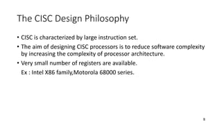
  • 7. 7 The RISC Design Philosophy • RISC is characterized by limited number of instructions • A complex instruction is obtained as a sequence of simple instructions.so,in RISC processor software is complex but the processor architecture is simple. • Large number of registers are required. • Pipelined instruction execution. Ex : ARM, ATMEL AVR, MIPS, Power PC etc
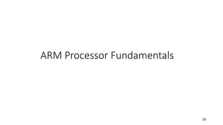
  • 8. 8 The CISC Design Philosophy • CISC is characterized by large instruction set. • The aim of designing CISC processors is to reduce software complexity by increasing the complexity of processor architecture. • Very small number of registers are available. Ex : Intel X86 family,Motorola 68000 series.
  • 9. 9 CISC vs. RISC Compiler Processor Code Generation Greater Complexity CISC Compiler Processor Code Generation Greater Complexity RISC
  • 10. 10 RISC – 4 major design rules • Instructions • Reduced Number of Instructions • Execute in a single cycle • The compiler synthesizes complicated operations • Each instruction is a fixed length
  • 11. 11 RISC – 4 major design rules • Pipelines • The processing of instructions is broken down into smaller units that can be executed in parallel by pipelines • Pipeline advances by one step on each cycle for maximum throughput
  • 12. 12 RISC – 4 major design rules • Registers • Have a large general purpose register set • Any register can contain either data or address • CISC has dedicated registers for specific purposes.
  • 13. 13 RISC – 4 major design rules • Load – Store Architecture • Separate load and store instructions transfers data between the register bank and external memory
  • 14. 14 The ARM Design Philosophy • Reduce power consumption • High code density • Reduce the area of the die taken up by the embedded processor • Incorporated hardware debug technology
  • 15. 15 Instruction set for Embedded Systems • Variable cycle execution for certain instructions • Inline barrel shifter leading to more complex instructions • Thumb 16 – bit instructions • Conditional execution • Enhanced Instructions
  • 17. 17 Agenda • Registers • CPSR • Pipeline • Exceptions, Interrupts and the Vector Table • Core Extensions • Architecture Revisions • ARM Processor Families • Summary
  • 18. 18 ARM core dataflow model Incrementer Address Register ALU Barrel Shifter MAC Register File r0 – r15 Sign Extend Instruction Decoder Read Data A B Acc Rd Result B A r15 pc Rn Rm N Address
  • 19. 19 ARM core dataflow model • Functional units connected by data buses • Data Bus  Data or Instruction • Von Neumann architecture  Data and instruction share the same bus • Load Store Architecture • Register File – 32 bit registers • ARM instruction has 2 source and 1 destination register • L/S inst: use the ALU to generate an address to be held in the address reg. and broadcast on the Address Bus • Result Bus
  • 20. 20 Registers – User Mode r0 r1 r2 r3 r4 r5 r6 r7 r8 r9 r10 r11 r12 r13 sp r14 lr r15 pc cpsr - • 32 bit in size • Hold either data or address • 16 data registers(r0 – r15) and 2 processor status register (cpsr & spsr) • r13, r14, r15 – Special functions • r13 (sp) –stores the head of the stack in the current processor mode • r14 (lr) – the core puts the return address whenever it calls a subroutine • r15 (pc) – contains the address of the next instruction to be fetched by the processor • Which register are visible to the programmer depend upon the current mode of the processor
  • 21. 21 Current Program Status Register • To monitor and control internal operations • Some ARM Processor core have extra bits allocated N Z C V I F T Mode 31 30 29 28 7 6 5 4 0 Condition Flags Processor Mode Interrupt Masks Thumb State Function Bit Fields Flags Status Extension Control
  • 22. 22 Processor Modes • Determines which registers are active and the access rights to the cpsr register itself • Privileged & Nonprivileged • Abort • Fast Interrupt Request • Interrupt Request • Supervisor • System • Undefined • User Privileged-R/W access to CPSR Nonprivileged-R Access to CF,R/W access to ConditionFlags
  • 23. 23 Processor Modes • Abort – Failed attempt to access memory • FIQ IRQ – Two interrupt levels available on the ARM processor • Supervisor – OS kernel operates • System – Special version of user mode that allows full R/W access to the cpsr • Undefined – processor encounters an instruction that is undefined • User – used in programs & applications • When a power is applied to the core it starts in supervisor mode.
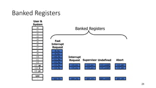
  • 24. 24 Banked Registers r0 r1 r2 r3 r4 r5 r6 r7 r8 r9 r10 r11 r12 r13 sp r14 lr r15 pc cpsr - r8_fiq r9_fiq r10_fiq r11_fiq r12_fiq r13_fiq r14_fiq spsr_fiq r13_irq r14_irq spsr_irq r13_svc r14_svc spsr_svc r13_undef r14_undef spsr_undef r13_abt r14_abt spsr_abt Fast Interrupt Request Interrupt Request Supervisor Undefined Abort User & System Banked Registers
  • 25. 25 Banked Registers • Banked registers are available only when the processor is in a particular mode • Every processor mode except user mode can change mode by writing directly to the mode bits of the cpsr • Banked registers are a subset of the main 16 registers • If we change processor mode, a banked register from the new mode will replace an existing register • Exceptions and Interrupts cause a mode change
  • 26. 26 Changing mode on an exception r0 r1 r2 r3 r4 r5 r6 r7 r8 r9 r10 r11 r12 r13 sp r14 lr r15 pc cpsr - User Mode r13_irq r14_irq spsr_irq Interrupt Request Mode • This change causes user register r13 and r14 to be banked • The user registers are replaced with registers r13_irq and r14_irq • spsr stores the previous mode cpsr
  • 27. 27 Processor Mode Mode Abbr: Privileged Mode[4:0] Abort abt yes 10111 Fast Interrupt Request fiq yes 10001 Interrupt Request irq yes 10010 Supervisor svc yes 10011 System sys yes 11111 Undefined und yes 11011 User usr no 10000 cpsr is not copied into the spsr when a mode change is forced due to a program writing directly to the cpsr.
  • 28. 28 State and Instruction Sets • There are three instruction sets • ARM • Thumb • Jazelle The Jazelle instruction set is a closed instruction set and is not openly available. To take advantage of Jazelle extra software has to be licensed from both ARM Limited and Sun Microsystems.
  • 29. 29 State and Instruction Sets ARM (cpsr T = 0) Thumb (cpsr T = 1) Instruction Size 32 bit 16 bit Core Instruction 58 30 Conditional Execution Most Only branch instructions Data Processing Instructions Access to barrel shifter and ALU Separate barrel and ALU instructions Program Status Register R/W in privileged mode No direct access Register Usage 15 GPR + PC 8 GPR + 7 high registers + PC
  • 30. 30 State and Instruction Sets Jazelle (cpsr T = 0, J = 1) Instruction Size 8 bit Core Instruction Over 60% of the java bytecodes are implemented in hardware; the rest of the codes are implemented in software
  • 31. 31 Interrupt Masks • Are used to stop specific interrupt requests from interrupting the processor • IRQ • FIQ • The I bit masks IRQ when set to binary 1, and F bit masks FIQ when set to binary 1
  • 32. 32 Condition Flags Flag Flag Name Set when Q Saturation The result causes an overflow and / or saturation V oVerflow The result causes a signed overflow C Carry The result causes an unsigned carry Z Zero The result is zero, frequently used to indicate the equality N Negative Bit 31 of the result is a binary 1
  • 33. 33 Condition Flags • Condition flags are updated by comparisons and the result of ALU operations that specify the S instruction suffix • If SUBS results in a register value of zero, then the Z flag in the cpsr is set
  • 34. 34 Condition Flags – Eg 0 0 1 0 0 1 0 10011 31 30 29 28 7 6 5 4 0 nzCvq svc i F t Function Bit Fields Flags Status Extension Control 0 24 0 27 j cpsr = nzCvqjiFt_SVC
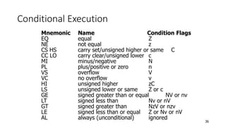
  • 35. 35 Conditional Execution • Conditional execution controls whether or not the core will execute an instruction • Most instructions have a condition attribute that determines if the core will execute it based on the setting of the condition flags • Prior to execution, the processor compares the condition attribute with the condition flags in the cpsr • If they match, then the instruction is executed, otherwise the instruction is ignored • When a condition mnemonic is not present, the default behaviour is set to always (AL) execute
  • 36. 36 Conditional Execution Mnemonic Name Condition Flags EQ equal Z NE not equal z CS HS carry set/unsigned higher or same C CC LO carry clear/unsigned lower c MI minus/negative N PL plus/positive or zero n VS overflow V VC no overflow v HI unsigned higher zC LS unsigned lower or same Z or c GE signed greater than or equal NV or nv LT signed less than Nv or nV GT signed greater than NzV or nzv LE signed less than or equal Z or Nv or nV AL always (unconditional) ignored
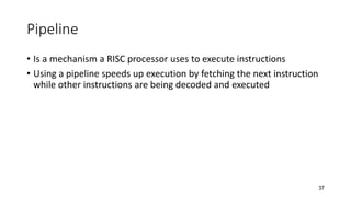
  • 37. 37 Pipeline • Is a mechanism a RISC processor uses to execute instructions • Using a pipeline speeds up execution by fetching the next instruction while other instructions are being decoded and executed
  • 38. 38 ARM7 Three stage pipeline • Fetch loads an instruction from memory • Decode identifies the instruction to be executed • Execute processes the instruction and writes the result back to a register Fetch Decode Execute
  • 39. 39 Pipelined instruction sequence ADD SUB ADD CMP SUB ADD Fetch Decode Execute Cycle 1 Cycle 2 Cycle 3 Time • Filling the pipeline • Allows the core to execute an instruction every cycle
  • 40. 40 ARM9 Five stage pipeline Fetch Decode Execute Memory Write • Higher operating frequency  higher performance • Latency increases • Increase in instruction throughput by around 13% in 5 stage pipeline • 1.1 Dhrystone MIPS per MHz
  • 41. 41 ARM9 Five stage pipeline • Fetch • The instruction is fetched from memory and placed in the instruction pipeline • Decode • The instruction is decoded and register operands read from the register file • Execute • An operand is shifted and the ALU result generated • Memory (Buffer/Data) • Data memory is accessed if required. Otherwise the ALU result is buffered for one clock cycle to give the same pipeline flow for all instructions • Write (Write-Back) • The results generated by the instruction are written back to the register file, including any data loaded from memory
  • 42. 42 ARM10 Six stage pipeline Fetch Decode Execute Memory Write Issue • Increase in instruction throughput by around 34% in 6 stage pipeline • 1.3 Dhrystone MIPS per MHz • Code written for the ARM7 will execute on ARM9 and ARM10
  • 44. 44 Pipeline Characteristics • An instruction in the execute stage will complete even though an interrupt has been raised • The execution of a branch instruction or branching by the direct modification of the PC causes the ARM core to flush its pipeline
  • 45. 45 Exceptions, Interrupts, and the Vector Table • When an exception or interrupt occurs, the processor set the PC to a specific memory address • The address is within a special address range called the vector table • The entries in the vector table are instructions that branch to specific routines designed to handle a particular exception or interrupt • When an exception or interrupt occurs,the processor suspends normal execution and starts loading instructions from the exception vector table.
  • 46. 46 Exceptions, Interrupts, and the Vector Table Exception / Interrupt Shorthand Address High Address Reset RESET 0x00000000 0xffff0000 Undefined Instruction UNDEF 0x00000004 0xffff0004 Software Interrupt SWI 0x00000008 0xffff0008 Prefetch Abort PABT 0x0000000C 0xffff000C Data Abort DABT 0x000000010 0xffff0010 Reserved - 0x000000014 0xffff0014 Interrupt Request IRQ 0x000000018 0xffff0018 Fast Interrupt Request FIQ 0x00000001C 0xffff001C
  • 47. 47 Exceptions, Interrupts, and the Vector Table • RESET – when power is applied, branches to initialization code • UNDEF – when the processor cannot decode an instruction • SWI – when a SWI instruction is called • PABT – attempts to fetch an instruction from an address without the correct access permissions • DABT –attempts to access data memory without the correct access permissions • IRQ – by external hardware • FIQ – by external hardware requiring faster response time
  • 48. 48 Core Extensions • Standard components placed next to the ARM core • Improve performance, manage resources, provide extra functionality • Three hardware extensions • Caches • Memory Management • Coprocessors
  • 49. 49 Caches • Cache is a block of fast memory placed between main memory and the core • Cache provides an overall increase in performance • ARM has two forms of cache • Single unified cache for data and instruction • Separate caches for data and instruction
  • 50. 50 Memory Management • MMU is a class of processor hardware components for handling memory accesses requested by the CPU. • The functions of MMU’s are • Translation of virtual address to physical address. • Memory protection • Cache control etc
  • 51. 51 Coprocessors • Coprocessors can be attached to the ARM processor • A separate chip,that performs lot of calculations for the microprocessor,relieving the CPU some of its work and thus enhancing overall speed of system. • A secondary processor used to speed up operation by taking over a specific part of main processors work. • The ARM processor uses coprocessor 15 registers to control cache, TCMs, and memory management
  • 52. 52 Architecture Revisions • Every ARM processor implementation executes a specific instruction set architecture (ISA) • ISA have more than one processor implementation
  • 53. 53 Nomenclature • ARM{x}{y}{z}{T}{D}{M}{I}{E}{J}{F}{-S} x - family y – memory management / protection unit z - cache T – Thumb 16 – bit decoder D – JTAG debug M – fast multiplier I – EmbeddedICE macrocell E – Enhanced instructions (assumes TDMI) J - Jazelle F – vector floating point unit S – Synthesizible version
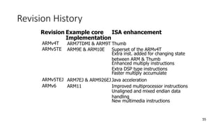
  • 54. 54 Revision History Revision Example core Implementation ISA enhancement ARMv1 ARM1 First ARM Processor 26 – bit addressing ARMv2 ARM2 32 – bit multiplier 32 – bit coprocessor support ARMv2a ARM3 On chip cache Atomic swap instruction ARMv3 ARM6 & ARM7DI 32 – bit addressing Separate cpsr & spsr Coprocessor 15 for cache management New modes – UNDEF, ABORT MMU support – virtual memory ARMv3M ARM7M Signed & unsigned long multiply inst. ARMv4 StrongARM Load – store instruction New Mode – system 26 bit addressing mode no longer supported
  • 55. 55 Revision History Revision Example core Implementation ISA enhancement ARMv4T ARM7TDMI & ARM9T Thumb ARMv5TE ARM9E & ARM10E Superset of the ARMv4T Extra inst. added for changing state between ARM & Thumb Enhanced multiply instructions Extra DSP type instructions Faster multiply accumulate ARMv5TEJ ARM7EJ & ARM926EJ Java acceleration ARMv6 ARM11 Improved multiprocessor instructions Unaligned and mixed endian data handling New multimedia instructions
  • 56. 56 Description of cpsr Description Parts Bits Architecture Mode 4:0 all processor mode T 5 ARMv4T Thumb state I & F 7:6 all interrupt masks J 24 ARMv5TEJ Jazelle state Q 27 ARMv5TE condition flag V 28 all condition flag C 29 all condition flag Z 30 all condition flag N 31 all condition flag
  • 57. 57 ARM processor families • ARM7, ARM9, ARM10 and ARM11 • 7, 9, 10, 11 indicate different core designs
  • 58. 58 ARM family attribute comparison (+ cache) ARM11 eight-stage 335 0.4 mW/MHz 1.2 Harvard 16 x 32 ARM7 three-stage 80 0.06 mW/MHz 0.97 Von Neumann 8 x 32 ARM10 six-stage 260 0. 5 mW/MHz 1.3 Harvard 16 x 32 (+ cache) ARM9 five-stage 150 0.19 mW/MHz 1.1 Harvard 8 x 32 (+ cache) Pipeline depth Typical MHz MIPS/MHz Multiplier Architecture mW/MHz
  • 59. 59 ARM processor variants E no yes Jazelle no ISA v4T yes Thumb yes v5TEJ yes CPU Core MMU /MPU Cache ARM7TDMI none none ARM7EJ-S none none no v4T no ARM720T MMU unified – 8K cache yes no v4T no ARM920T MMU separate – 16K/16K yes D + I cache v4T no ARM922T MMU separate – 8K/8K yes D + I cache no v5TEJ yes ARM926EJ-S MMU separate – cache yes TCM configurable yes v4T no ARM940T MPU separate – 4K/4K yes D + I cache no v5TE no ARM946E-S MPU separate – cache yes TCM configurable yes v5TE no ARM966E-S none separate – TCM yes configurable no
  • 60. 60 ARM processor variants E yes Jazelle no ISA v5TE Thumb yes CPU Core MMU /MPU Cache ARM1020E MMU D + I cache separate – 32K/32K yes no v5TE yes ARM1022E MMU D + I cache separate – 16K/16K yes yes v5TE yes ARM1026EJ-S MMU MPU TCM configurable separate – cache yes yes v6 yes ARM1136J-S MMU TCM configurable separate – cache yes yes v6 yes ARM1136F-S MMU TCM configurable separate – cache
  • 61. 61 Cortex Family • ARM Cortex-A Series - Application processors for complex OS and user applications • ARM Cortex-A8, ARM Cortex-A9 • ARM Cortex-R Series - Embedded processors for real-time systems • ARM Cortex-R4(F) • ARM Cortex-M Series – Embedded processors optimized for cost sensitive applications, as Mobile devices • ARM Cortex-M0, ARM Cortex-M1, ARM Cortex-M3
  • 62. 62 Specialized Processors • StrongARM • Digital Semiconductor + Intel • PDAs • Low power consumption • Harvard Architecture • 5 stage pipeline • No thumb support
  • 63. 63 Summary • Data flow in an ARM core. • 3 instruction sets • Register file • Extensions • Caches • Memory Management • Coprocessors • ISA