


![Locale formatOperating System
fr_FR.ISO8859-1Sun Solaris
Français (France) [fr-FR]Infoview 6.5.1
To simplify the documentation and the application, the same term "language" may be used for both
language and locale meanings.
1.7.3 The different locales
DefinitionTerms
This is the universe design tool user interface
language. The menu and messages appear in
that language.
Product language
Your preferred viewing language settings. This
defines the locale in which strings, text and format
- the parts of the resource (document or universe)
content or attribute list - appear in the application
on InfoView or Web Intelligence Rich Client.
Preferred viewing locale (PVL)
The locale used when your preferred viewing lo-
cale is not available.
Substitution (Fallback) locale
The locale in which the document has been cre-
ated.
Source language
1.7.4 Setting the product language for the universe design tool user interface
In the General tab of the Tools > Options settings of the universe design tool, choose a Language
from the list of available languages, this is the product language, also known as the User Interface
Language (UIL). There is no impact on the universe metadata: object names, context names, and
classes appear in the original language of the database elements. To translate the universe metadata,
use the translation management tool.
2011-04-1430
Introducing the universe design tool](https://image.slidesharecdn.com/xi4sp2universedesigntoolen-140522041756-phpapp01/85/Xi4sp2-universe-design_tool_en-30-320.jpg)


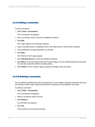


![3.4.14.5 BLOB_COMPARISON
BLOB_COMPARISON = Yes|No
Yes/NoValues
NoDefault
NoCan be edited?
Species if a query can be generated with a DISTINCT statement when
a BLOB file is used in the SELECT statement. It is related to the setting
No Duplicate Row in the query properties.
Yes: The DISTINCT statement can be used within the query.
No: The DISTINCT statement cannot be used within the query even if
the query setting No Duplicate Row is on.
Description
3.4.14.6 BOUNDARY_WEIGHT_TABLE
BOUNDARY_WEIGHT_TABLE = Integer 32bits [0-9]
Integer 32bits [0-9, or a negative integer]Values
-1Default
2011-04-14110
Creating a universe and setting the universe parameters](https://image.slidesharecdn.com/xi4sp2universedesigntoolen-140522041756-phpapp01/85/Xi4sp2-universe-design_tool_en-110-320.jpg)


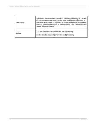
![NoDefault
Specifies how multiple SQL statements are handled. Multiple statements
can be combined (provided that the database permits this).
Yes: Specifies that multiple SQL statements are combined.
No: Specifies that multiple SQL statements are not combined. This is
the default value.
Description
3.4.14.24 MAX_INLIST_VALUES
MAX_INLIST_VALUES = [0-99]
Integer: min-1, max depends on DBValues
-1Default
Allows you to set the maximum number of values you may enter in a
condition when you use the IN LIST operator.
99: Specifies that you may enter up to 99 values when you create a
condition using the IN LIST operator.
The maximum authorized value you may enter depends on your
database.
The value of -1 means that there is no restriction on the number of values
returned, except that imposed by the database.
Description
3.4.14.25 OLAP_UNIVERSE
OLAP_UNIVERSE = Yes|No
2011-04-14122
Creating a universe and setting the universe parameters](https://image.slidesharecdn.com/xi4sp2universedesigntoolen-140522041756-phpapp01/85/Xi4sp2-universe-design_tool_en-122-320.jpg)


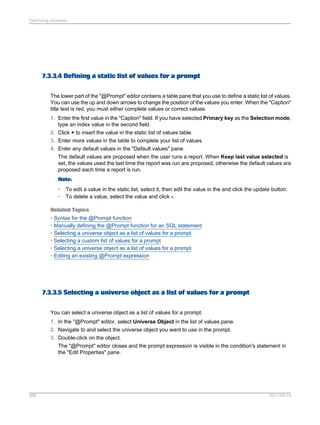
![• Add an object (dimension, measure, or detail) to the "Result" pane of the "Query Panel" in Web
Intelligence.
• Add a universe pre-defined filter to the "Filter" pane of the "Query panel", even if no object that
belongs to the same class has been selected in the Result pane.
• Create a filter with an object (dimension, measure, or detail) that belongs to a class with a
mandatory filter.
A mandatory filter can have default values or be associated with a list of values.
A mandatory filter is hidden and cannot be selected in the "Query Panel" in Web Intelligence. In the
universe design tool, when you set a filter as mandatory in the query, then it is hidden automatically
and the Show Item(s) command is disabled. If you uncheck the mandatory option, the filter is no longer
hidden. The Hide Item(s) command is enabled.
An end-user query can include more than one mandatory filter. By default, all mandatory filters are
joined in the query with the AND operator.
All sub-classes inherit the mandatory filters from the parent class. Note, however:
• An object (dimension, measure, detail) that references another object with the @Select function
does not inherit the class mandatory filter of the referenced object.
• A WHERE clause of an object that references another object where clause with the @Where function
does not inherit the class mandatory filter of the referenced object.
• A pre-defined filter that references another pre-defined filter or an object where clause with the
@Where function does not inherit the class mandatory filter of the referenced object.
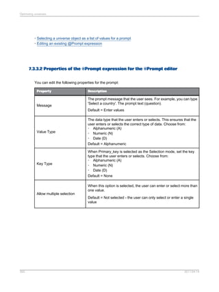
Example: Mandatory filter in an OLAP universe
The following filter (shown in XML code) authenticates the code entered by a user in a prompt.
<FILTER KEY="[BCOMUSI]">
<CONDITION OPERATORCONDITION="InList">
<CONSTANT TECH_NAME=
"@Prompt('CO_CODE Char User MultiSingle Man Def',
'A','Company codeLov[BCOMUSI]Base',
multi,primary_key)"/>
</CONDITION>
</FILTER>
Related Topics
• Mandatory filters examples
• Mandatory filters and list of values
6.6.16.3.1 Mandatory filters examples
The following examples show how universe mandatory filters can be used:
To verify the Login entered by a user with a Login stored in a table:
1 = (Select 1 from Club.dbo.Login
where Login = @Variable('BOUSER')
AND Password = @Prompt('Password?','A',,mono,free) )
2011-04-14320
Creating universes](https://image.slidesharecdn.com/xi4sp2universedesigntoolen-140522041756-phpapp01/85/Xi4sp2-universe-design_tool_en-320-320.jpg)


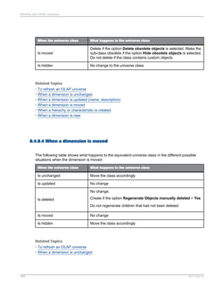
![DescriptionProperty
Optional. The 'default value' parameter is used to define
default values presented to the user. When you use a hard-coded
list, the default values entered here must be present in the [lov]
list.
For example, for a single value:
{'France'}
For a pair of values:
{'France':'F'}
For two pairs of values:
{'France':'F','Germany':'G'}
When refreshing a document, these values are displayed by default,
but if the persistent option is set, then the last values used in
the prompt are used instead of the default values.
You can have single values or pairs of values.
If you specify the primary_key parameter in the prompt definition,
then you must provide the key values.
'default value'
7.3.3.10 Examples: Using the @Prompt function
The following are examples of @Prompt syntax.
Minimal use of the @Prompt function:
@Prompt('Displayed text ','A',,,)
Using the @Prompt with a LOV without default values:
@Prompt('Displayed text ','A',{'Paris','London','Madrid'},,)
Using the @Prompt with a LOV and one default value:
@Prompt('Displayed text ','A',{'Paris','London','Madrid'},,,,{'Paris'})
2011-04-14403
Optimizing universes](https://image.slidesharecdn.com/xi4sp2universedesigntoolen-140522041756-phpapp01/85/Xi4sp2-universe-design_tool_en-403-320.jpg)

![(value, key) such as: {'England: 21', ‘Scotland:39’}. The user must choose only one region, so the
Mono parameter is set. The default value must appear in the list of values.
SELECT dbo.region.sales_region
FROM dbo.region
WHERE dbo.region.region_id = @Prompt('Choose a region','A:N',
{'England':'21', 'Scotland':'39', 'Wales':'14'},
Mono, primary_key, Persistent, {'Scotland':'39'})
This feature will also allow you to perform the behavior of the CASE WHEN ELSE clause on databases
that do not support it, especially OLAP databases.
Example: @Prompt syntax to create a predefined condition using a match pattern prompt
The example below allows the user to select a client name by entering the first letter of the name. If
the Web Intelligence user enters H%, then the report returns all the clients with the last name starting
with H.
(@Select(ClientClient Name)
LIKE (@Prompt('enter','A',,,)+%)
To allow the client to use either uppercase or lowercase letters, the syntax is:
(@Select(ClientClient Name)
LIKE lower(@Prompt('enter','A',,,)+%) OR
(@Select(ClientClient Name)
LIKE upper(@Prompt('enter','A',,,)+%)
7.3.3.11 Syntax for the @Prompt function
The syntax for the @Prompt function is complex due to the versatility of this function. You write the
prompt a message and specify the data type, if the data is a single value or multiple values, if the data
is persistent, and you can specify default values. The syntax is shown below:
@Prompt('message','type',[lov],Mono|Multi,
free|constrained|primary_key,persistent|not_persistent,[default_values])
Related Topics
• @Prompt
• Manually defining the @Prompt function for an SQL statement
• Properties of the @Prompt expression for manually defining a prompt
2011-04-14405
Optimizing universes](https://image.slidesharecdn.com/xi4sp2universedesigntoolen-140522041756-phpapp01/85/Xi4sp2-universe-design_tool_en-405-320.jpg)
![7.3.4 @Script
The @Script function returns the result of a Visual Basic for Applications macro (VBA macro). VBA
macros can only run in a Windows environment. You use the @Script function to run a specified VBA
macro each time a query that includes the object is refreshed or run.
You would typically use a @Script function in a WHERE clause to run a more complex process than
a simple prompt box (@Prompt function). VBA macros are stored in BusinessObjects report files (.REP).
The default directory for these reports is the UserDocs folder in the BusinessObjects path, however,
you can define any folder to store .REP files.
Note:
@Script is only supported with universe design tool and the client version of Desktop Intelligence or
Desktop Intelligence Three-tier Mode. You are strongly advised to avoid using the @Script function
for any use beyond the client version of Desktop Intelligence. It is not supported with the server version
of Desktop Intelligence available in InfoView for publishing or scheduling Desktop Intelligence reports,
and Web Intelligence. In the case of Web Intelligence, you should not use the @Script function, but
stay with a simpler design using the @Prompt function for interactive objects.
7.3.4.1 Syntax for the @Script function
The syntax for the @Script function is as follows:
@Script('var_name', ['var_type'], 'script_name')
Note:
The second argument is optional; however, if it is omitted, you must still include commas as separators.
The syntax is described in the following table:
DescriptionSyntax
Variable name declared in the macro. This name
enables the results of the executed macro to be
recovered in the SQL definition of an object. This
name must be identical in both the VBA macro
and in the SQL definition of the object.
'var_name'
2011-04-14406
Optimizing universes](https://image.slidesharecdn.com/xi4sp2universedesigntoolen-140522041756-phpapp01/85/Xi4sp2-universe-design_tool_en-406-320.jpg)


![7.4.3.1 Accessing external strategies
External strategies appear in the drop down list boxes that also list the built-in strategies on the Strategies
page. Each drop down list box corresponds to a strategy type category in the XML file. An external
strategy appears in the list with External Strategy prefixing the strategy name as follows:
External Strategy:<strategy name>
For example, an external strategy for join creation called Constraints in the Strategy file, appears as
External Strategy:Constaints in the Joins drop down list on the Strategies page.
7.4.4 Creating Help text for external strategies
On the Strategies page, a commentary note appears under each selected strategy. This is the Help
text for the strategy. For built-in strategies the Help text cannot be accessed or edited. However, you
can access and edit the Help text for external strategies.
Note:
In previous versions of the universe design tool the Help text was included in the strategy text file in
the section [HELP]. The text in this section is now stored in a separate file, the external strategy language
file described below.
7.4.4.1 External strategy Help text is stored in a separate file
The Help text for external strategies is stored in a separate external strategy language file called
<RDBMS><language>.stg. For example, oaracleen.stg is the Help text file for the strategies in the
oracle.stg file.
You can edit and customize Help text entries. The Help text should describe briefly what the strategy
does to help designers who may not be familiar with the strategy.
For each external strategy that appears in the external strategy file, you should ensure that a
corresponding entry with Help text appears in the external strategy language file.
There is a strategy language file for each language version of the universe design tool that you have
installed. The external strategy language file is in the same directory as the external strategy file. For
2011-04-14420
Optimizing universes](https://image.slidesharecdn.com/xi4sp2universedesigntoolen-140522041756-phpapp01/85/Xi4sp2-universe-design_tool_en-420-320.jpg)


![7.4.8.1 The output format of object strategies (OBJECT)
The output format of an object strategy contains nine columns. You must ensure that your output
includes all these columns even if they contain null values. All returned values have to be separated
with a pipe '|' character. The pipe has to be appended at the end of the returned values.
DescriptionColumn contains...Column number
Table name format is [Qualifi-
er.][Owner.]Table where each
name can have up to 35 charac-
ters. If you leave this column
empty, then the tables are ob-
tained from the Select (fifth col-
umn) and Where (sixth column).
Table1
Name of the column.Column Name2
Name of a class. Subclasses
are written as follows:
ClassSubclass format.
Class Name3
Name of the object or condition.
If the object name is empty, then
a class and its description are
created.
Object Name4
Select statement.Select5
If you leave the Select column
empty, but include a Where
clause, then a predefined condi-
tion and its description are creat-
ed.
Where:6
C (Character), N (Numeric), D
(Date), T (Long Text). If the col-
umn is left empty, the default is
N.
Type7
2011-04-14426
Optimizing universes](https://image.slidesharecdn.com/xi4sp2universedesigntoolen-140522041756-phpapp01/85/Xi4sp2-universe-design_tool_en-426-320.jpg)


![• Syntax that you can use for analytic, RISQL, and OLAP functions in the Select statement.
• How you can verify and modify PRM files to ensure the support of unlisted analytic functions.
• RDBMS specific rules and restrictions for the use of analytic functions.
• Inserting analytic function syntax automatically when editing Select statements.
7.5.5 IBM DB2 UDB and Oracle
You can use the same syntax for analytic functions for both RDBMS.
7.5.5.1 Defining the SELECT statement for DB2, UDB, and Oracle RDBMS
You define an analytic function in the SELECT statement for an object. You need to type the syntax in
one of the edit boxes for the Select statement.
Note:
You can automate syntax entry by adding analytic functions to the Functions list in the Edit Select
Statement dialog box. To make a function available in the Functions list, you need to add the analytic
function to the [FUNCTIONS] section of the .prm file. See the section Inserting syntax automatically in
Select statements for more information.
Analytic functions are identified by the keyword OVER; for example:
RANK() OVER (PARTITION BY calender.cal_year ORDER BY SUM(telco_facts.total_billed_rev)DESC)
The clause that follows the OVER keyword defines the partition, and how the rows are ordered in the
result table.
The syntax for each family of analytic functions is described as follows:
2011-04-14435
Optimizing universes](https://image.slidesharecdn.com/xi4sp2universedesigntoolen-140522041756-phpapp01/85/Xi4sp2-universe-design_tool_en-435-320.jpg)


![Preventing use of an analytic object in a condition or sort
To prevent the use of an analytic function in a condition or sort:
1. Right-click the object in the universe design tool.
2. Select Object Properties from the contextual menu.
The "Edit Properties" dialog appears.
3. Clear the Condition and Sort check boxes in the "Can be used in" group box.
4. Click OK.
7.5.6 RedBrick (RISQL functions)
The following sections describe how you can use RISQL functions in the universe design tool.
7.5.6.1 Defining the SELECT Statement for RedBrick RISQL Functions
You define an analytic function in the SELECT statement for an object. You need to type the syntax in
one of the edit boxes for the Select statement.
Note:
You can automate syntax entry by adding RISQL functions to the Functions list in the Edit Select
Statement dialog box. To make a function available in the Functions list, you need to add the RISQL
function to the [FUNCTIONS] section of the PRM file. See the section Inserting syntax automatically in
Select statements for more information.
2011-04-14439
Optimizing universes](https://image.slidesharecdn.com/xi4sp2universedesigntoolen-140522041756-phpapp01/85/Xi4sp2-universe-design_tool_en-439-320.jpg)


![• An OLAP function cannot be used in the same Select statement as another function.
• An OLAP function cannot be based on another function.
• OLAP functions are not supported as user objects.
7.5.8 Inserting syntax automatically in Select statements
You can automate the insertion of analytic function syntax by adding the analytic function to the Functions
list box in the Edit Select Statement dialog box.
You populate the Functions list box by adding the analytic function to the list of functions under the
[FUNCTION] section in the appropriate PRM file for the target RDBMS.
Once added to the PRM file, the function becomes available in the Functions list box in the Edit Select
Statement dialog box. When you double click the function syntax, the defined syntax is inserted in the
edit box.
When you add the analytic function to the PRM file, you must set the following values:
DescriptionParameter
Analytic, RISQL, and OLAP functions cannot
generate a GROUP BY clause. By setting the
value N, you prevent the analytic function from
being used in a GROUP BY clause.
GROUP = N
This prevents the analytic function for DB2 UDB
and Oracle from being used in user objects. For
RedBrick and Teradata, this value can be set at
Y.
For IBM DB2 UDB v.7.1 and ORACLE 8.1.6 only:
IN_MACRO = N
You can add an analytic function to the [FUNCTION] section in the PRM file as follows:
To add an analytic function to the PRM file:
1. Browse to the Data Access directory in the Business Objects path.
2. Open the PRM file for your RDBMS in a text editor.
3. Scroll to the [FUNCTION] section of the PRM file.
4. Copy an existing function and paste it at the end of the list.
5. Type a unique number for the newly pasted function, and modify the values as appropriate for the
analytic function that you want to add to the list.
2011-04-14445
Optimizing universes](https://image.slidesharecdn.com/xi4sp2universedesigntoolen-140522041756-phpapp01/85/Xi4sp2-universe-design_tool_en-445-320.jpg)


![• Navigation/Member functions (ANCESTOR, ASCENDANTS...)
• Metadata functions (AXIS, HIERARCHY...)
8.3.10 XML syntax for filter and WHERE statements
This section describes the XML syntax for defining the WHERE clause or filter statements in your OLAP
universe. You must add the FILTER or FILTER EXPRESSION tags manually, and then enter your
expression between the tags either manually or with the universe design tool MDX editor.
• Use <FILTER= "your_object_definition"> when using a single object definition. Enter your object
definition inside the double quotes.
• Use <FILTER EXPRESSION= "yourcomplexMDX_expression"> when using a complex MDX
expression containing one or more objects. Enter your expression inside the double quotes.
The syntax for a single filter object is as follows:
<FILTER = “your_object_definition”><CONDITION OPERATORCONDITION="yourOpera
tor"><CONSTANT VALUE="your_Value"/></CONDITION></FILTER>
Where:
• yourMDX_expression is the single object definition, enclosed in double quotes.
• CONSTANTVALUE is either CONSTANT CAPTION or CONSTANT TECH_NAME
• yourOperator is the filter expression operator (equals, inlist...). When the InIist operator
is used, you must insert a CONSTANT CAPTION or CONSTANT TECH_NAME element for each item
in the list.
• your_Value is the defined filter value when CONSTANT CAPTION is used, or the object identifier
if CONSTANT TECH_NAME is used.
The syntax for a single filter object using the InList operator, where three countries are listed, is as
follows:
<FILTER= "your_object_definition "><CONDITION OPERATORCONDITION="InList"><CON
STANT CAPTION="England"/><CONSTANT CAPTION="France"/><CONSTANT CAPTION="Ger
many"/></CONDITION></FILTER>
The syntax for a complex filter expression and the TECH_NAME for the filtered value is as follows:
<FILTER EXPRESSION="yourComplex_MDX_Expression"><CONDITION OPERATORCONDI
TION="Equal"><CONSTANT TECH_NAME="1"/></CONDITION></FILTER>
Example: Filter with a calculated member in the filter expression
<FILTER EXPRESSION="IIF([0CALYEAR].CurrentMember > “2000”, 1,0)"><CONDITION
OPERATORCONDITION="Equal"><CONSTANT CAPTION="1"/></CONDITION></FILTER>
2011-04-14477
Working with OLAP universes](https://image.slidesharecdn.com/xi4sp2universedesigntoolen-140522041756-phpapp01/85/Xi4sp2-universe-design_tool_en-477-320.jpg)
![8.3.11 Predefined conditions in OLAP universes
Predefined conditions in OLAP universes are like conditions in non-OLAP universes except that you
define the WHERE clause using XML rather than SQL. You can declare filters manually, or by using
the Predefined filter editor.
8.3.11.1 XML Syntax for predefined filter options
Syntax for predefined conditions
A single predefined condition may contain multiple filters combined with the AND and OR operators.
By default, all filters are combined with the AND operator. To include filters using OR, you must use
the AND and OR operator tags.
The functions @Select, @Prompt and @Variable are allowed in the predefined filter definition.
Predefined filters can include one or multiple prompts. Prompts can be mandatory or optional.
Example: Using AND and OR tags for pre-defined conditions
<OPERATOR VALUE="AND">
<FILTER "[Level Object definition]">
<CONDITION OPERATORCONDITION="Operator">
<CONSTANT Level Attribute="Value"/>
</CONDITION>
</FILTER>
<OPERATOR VALUE="OR">
<FILTER "[Level Object definition]">
<CONDITION OPERATORCONDITION="Operator">
<CONSTANT Level Attribute="Value"/>
</CONDITION>
</FILTER>
<FILTER “[Level Object definition]">
<CONDITION OPERATORCONDITION="Operator">
<CONSTANT Level Attribute="Value"/>
</CONDITION>
</FILTER>
</OPERATOR>
</OPERATOR>
8.3.11.2 Manually creating pre-defined conditions in an OLAP universe
To create a pre-defined condition:
1. In universe design tool, open an OLAP universe and click the conditions radio button at the bottom
of the Universe pane.
2011-04-14478
Working with OLAP universes](https://image.slidesharecdn.com/xi4sp2universedesigntoolen-140522041756-phpapp01/85/Xi4sp2-universe-design_tool_en-478-320.jpg)
![The conditions view of the Universe pane appears. It contains a tree view of the classes in the
universe.
2. Right-click a class and select Condition... from the contextual menu.
3. In the Where: box, edit the XML template filter.
The template filter has the format:
<FILTER "[Level Object definition]">
<CONDITION OPERATORCONDITION="Operator">
<CONSTANT Level Attribute="Value"/
</CONDITION>
</FILTER>
Replace the elements in the template as follows:
Possible Values:Template element:
Enter the dimension level or measure implied in the filter. Enter the object
definition not the object name.
Level Object definition
Enter one of:
• Equal
• NotEqual
• Greater
• Less
• GreaterOrEqual
• LessOrEqual
• Between
• NotBetween
• InList
• NotInList
• Like
• NotLike
Operator
Enter one of:
• NAME
• CAPTION
• TECH_NAME
• DESCRIPTION
Level Attribute
Enter the value or a prompt. Define one value per CONSTANT tag.Value
An example of an edited predefined condition:
<FILTER KEY="[0D_DIV].[LEVEL01]">
<CONDITION OPERATORCONDITION="InList">
<CONSTANT CAPTION="Internal"/>
2011-04-14479
Working with OLAP universes](https://image.slidesharecdn.com/xi4sp2universedesigntoolen-140522041756-phpapp01/85/Xi4sp2-universe-design_tool_en-479-320.jpg)
![<CONSTANT CAPTION="Service"/>
</CONDITION>
</FILTER>
4. Click Parse to review the syntax and fix any errors.
5. Click OK to save the condition.
Related Topics
• Predefined conditions in OLAP universes
• Optional prompts in OLAP universes
8.3.11.3 About the Pre-defined Filter editor
The "Pre-defined filter" editor is for editing pre-defined filters in OLAP universes. Use it to select objects,
operators, lists of values, prompts, functions, and other optional elements that can be used to define a
filter for your OLAP universe.
In the condition properties panel of a filter, you can manually type the filter expression or click >> to
open the "Pre-defined filter" editor. When the editor is open, you can insert an @Prompt in the filter
expression: Right-click at the appropriate point in the filter expression and select New @Prompt from
the shortcut menu. The pre-defined filter editor inserts the filter expression in the query/object definition.
Example: Restriction on dimension Customer at the country level to restrict country to
Canada
<FILTER KEY="[Customer].[Country].[Country]"> <CONDITION OPERATORCONDITION="Equal">
<CONSTANT CAPTION="Canada" /> </CONDITION> </FILTER>
Related Topics
• About the options for the Pre-defined Filter editor
• Editing a pre-defined filter with the pre-defined filter editor
• About MDX functions for cube queries
8.3.11.4 About the options for the Pre-defined Filter editor
The "Pre-defined Filter" editor allows you to easily define a universe filter for an OLAP universe. You
can define the following options:
2011-04-14480
Working with OLAP universes](https://image.slidesharecdn.com/xi4sp2universedesigntoolen-140522041756-phpapp01/85/Xi4sp2-universe-design_tool_en-480-320.jpg)
![DescriptionOption
Select an operator from the available list. Default = EqualSelect an Operator
Filter either on an existing universe object or on a free definition (for example:
[Measures].[Internet Sales Amount]). Default = Universe object.
Base the filter on
Select a list of objects in the current universe when filter based on existing
object. Default selection = The Root class in the list of objects.
Select a LoV
Define values to compare the object/expression to. Depending on selected
operator, there are one or two sets of values to enter. Values can either be
static or based on a prompt. Default = Static values.
Comparison values
Edit a prompt manually, or use the "@Prompt" editor. Click >> to open the
"@Prompt" editor.
Insert a Prompt
Enable the index awareness function. Primary keys must be declared for this
to work correctly. When index awareness is set up in the universe design tool,
the primary and foreign key columns are used to speed up data retrieval and
to allow the universe design tool to generate more efficient SQL filters. Default
= Not selected.
Set Index Awareness
When selected, this encloses the filter expression inside <EXPRESSION>
</EXPRESSION> tags. Default = Not selected.
Use calculated expres-
sion
Set the current filter expression as optional. This applies to the current filter
expression in the filter editor only and not to the entire pre-defined condition
object. Default = Not selected.
Optional
Note:
"Optional" tags cannot be used for pre-defined filters in Web Intelligence. If these tags are used, they
are treated as a mandatory part of the query, therefore preventing the query from running.
Related Topics
• Editing a pre-defined filter with the pre-defined filter editor
8.3.11.5 Editing a pre-defined filter with the pre-defined filter editor
You are editing a filter in an OLAP universe.
The "Pre-defined Filter" editor is updated as you select or enter the values. You can right-click in the
filter expression to insert an @Prompt expression in the filter expression. When you right-click and
select New @Prompt, the "Prompt" editor opens.
1. In the "Properties" pane of the condition (filter) pane, click >>.
2011-04-14481
Working with OLAP universes](https://image.slidesharecdn.com/xi4sp2universedesigntoolen-140522041756-phpapp01/85/Xi4sp2-universe-design_tool_en-481-320.jpg)
![The "Pre-defined Filter" editor appears.
2. To base the filter on a universe object, select Universe object and choose an object from the
"Available Objects" pane. To base the predefined filter on your own expression, select "Free definition"
and type the expression in the "Available Objects" pane.
3. Select an operator from the "Operators" list. Multiple values (right operand) are allowed for the In
List and Not In List operators only.
4. Select Static value to define one or more fixed values, or select Prompt to insert a prompt expression.
When you select Prompt , the Edit button is activated. Click Edit to open the "@Prompt" editor and
define the prompt expression as required.
5. Click OK to validate the filter definition.
The parser checks the syntax for errors, including the integrity check. If errors are found a warning
message with error message is shown. When no errors are found, the new condition object is added
to the universe with the filter definition.
Related Topics
• About the options for the Pre-defined Filter editor
• About the Pre-defined Filter editor
8.3.12 Optional prompts in OLAP universes
Universes generated from OLAP data sources support optional prompts.
For SAP NetWeaver BW optional variables, filters with the optional conditions are automatically generated
in the universe.
In pre-defined conditions or in an object's WHERE clause, to make a prompt optional, embed the XML
filter expression between the two XML tags: <OPTIONAL> and </OPTIONAL>.
Example: Optional prompt in a pre-defined condition
<OPTIONAL>
<FILTER KEY="[Products].[Family]" >
<CONDITION OPERATORCONDITION="InList" >
<CONSTANT CAPTION="@prompt('Enter value(s) for Product family:','A','ProductsFamily',Multi,pri
mary_key,persistent)"/>
</CONDITION>
</FILTER>
</OPTIONAL>
Related Topics
• Manually creating pre-defined conditions in an OLAP universe
2011-04-14482
Working with OLAP universes](https://image.slidesharecdn.com/xi4sp2universedesigntoolen-140522041756-phpapp01/85/Xi4sp2-universe-design_tool_en-482-320.jpg)
![8.3.13 To improve performance of certain queries on SAP NetWeaver BW universes
For queries on SAP NetWeaver BW universes that include only the key and medium name detail objects
of a dimension, you can modify the generated syntax of the objects to improve query performance.
To modify the syntax:
1. Open the universe in universe design tool.
2. Double click the key detail object you want to modify.
3. In the Select text box on the "Definition" tab of the "Edit Properties" dialog box, change the syntax
to refer to the NAME attribute of the SAP characteristic.
For example, for the object L01 Customer Key, change the generated select syntax:
[Z_CUSTOM].[LEVEL01].[[2Z_CUSTOM]].[Value]
to refer to the NAME attribute:
[Z_CUSTOM].[LEVEL01].[NAME]
4. Click OK to save the changes.
5. Follow the same steps for the name object. Change the syntax to refer to the DESCRIPTION attribute
of the SAP characteristic.
For example, for the object L01 Customer Medium Name, change the generated select syntax:
[Z_CUSTOM].[LEVEL01].[[5Z_CUSTOM]].[Value]
to refer to the DESCRIPTION attribute:
[Z_CUSTOM].[LEVEL01].[DESCRIPTION]
8.4 OLAP universe lifecycle management
8.4.1 About OLAP universe lifecycle management
Note:
When you open a universe created with a version of Universe Designer prior to XIR3.1 SP2, you must
refresh and save the universe before making any changes in the universe or in the OLAP source.
2011-04-14483
Working with OLAP universes](https://image.slidesharecdn.com/xi4sp2universedesigntoolen-140522041756-phpapp01/85/Xi4sp2-universe-design_tool_en-483-320.jpg)


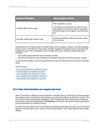


![For each mandatory filter, two dimension objects are created as reference objects for the @Prompt
function to display the expected list of values. The list of values dimensions are hidden in the universe.
They are necessary for the correct functioning of the prompt so must not be deleted and must be moved
or modified carefully.
Default values for variables are defined in the @Prompt function in the filter using the primary key,
persistent/not persistent, and default values parameters. The @Prompt function syntax can be seen in
the Properties page of the filter in the universe.
To avoid conflict between BW variables and filters defined by Web Intelligence users, objects involved
in an SAP variable definition are generated with the option Can be used in Condition unchecked in
the "Advanced" page of the object properties. This restricts Web Intelligence users from including
dimensions involved in SAP variables in the Filter pane.
Example: WHERE clause generated for an SAP BW variable
This example shows the WHERE clause generated for a BW variable on dimension object Customer2.
The syntax for the generated WHERE clause for a variable can be seen on the Properites page of
the filter.
<FILTER KEY="[Z_VAR002]">
<CONDITION OPERATORCONDITION="Equal">
<CONSTANT TECH_NAME="@Prompt(
'Customer Variable Single Value Mandatory',
'A',
'Customer2LovCustomer Variable Single Value MandatoryBase',
mono,
primary_key)"/>
<CONDITION>
</FILTER>
The prompt text is generated from the BW variable name. You can edit the text to make it more
descriptive.
Customer2LovCustomer Variable Single Value MandatoryBase is the name of the
hidden universe object that is used to build the list of values.
Note:
If you rename the class or move the list of values object to another folder, you must update the syntax
in the filter key.
8.5.1.4.2 How variables and lists of values are supported
A BEx Query can contain more than ten variables, which means that ten or more lists of values can be
loaded. Loading and refreshing lists of values can have an important impact on performance. The
following options are available for improving query performance for queries with variables:
• At universe generation time, all SAP BW variables (except key date) are mapped to mandatory
filters. By default, the filter objects are not associated with a list of values (except for hierarchy node
variables). You must explicitly associate a list of values in the object properties page.
• Optional variables are generated as optional prompts. An optional prompt does not automatically
load the list of values at query run time.
2011-04-14525
Working with OLAP universes](https://image.slidesharecdn.com/xi4sp2universedesigntoolen-140522041756-phpapp01/85/Xi4sp2-universe-design_tool_en-525-320.jpg)


Xi4sp2 universe design_tool_en
- 1. Universe design tool ■ SAP BusinessObjects Business Intelligence platform 4.0 Support Package 02 2011-04-14
- 2. © 2011 SAP AG. All rights reserved.SAP, R/3, SAP NetWeaver, Duet, PartnerEdge, ByDesign, SAP Business ByDesign, and other SAP products and services mentioned herein as well as their respective Copyright logos are trademarks or registered trademarks of SAP AG in Germany and other countries. Business Objects and the Business Objects logo, BusinessObjects, Crystal Reports, Crystal Decisions, Web Intelligence, Xcelsius, and other Business Objects products and services mentioned herein as well as their respective logos are trademarks or registered trademarks of Business Objects S.A. in the United States and in other countries. Business Objects is an SAP company.All other product and service names mentioned are the trademarks of their respective companies. Data contained in this document serves informational purposes only. National product specifications may vary.These materials are subject to change without notice. These materials are provided by SAP AG and its affiliated companies ("SAP Group") for informational purposes only, without representation or warranty of any kind, and SAP Group shall not be liable for errors or omissions with respect to the materials. The only warranties for SAP Group products and services are those that are set forth in the express warranty statements accompanying such products and services, if any. Nothing herein should be construed as constituting an additional warranty. 2011-04-14
- 3. Contents Introducing the universe design tool.....................................................................................15Chapter 1 Overview................................................................................................................................151.1 Universe design tool and universe fundamentals....................................................................151.2 What is a universe?................................................................................................................151.2.1 What is the role of a universe?...............................................................................................161.2.2 What does a universe contain?...............................................................................................161.2.3 About the universe window....................................................................................................181.2.4 Universe design tool install root path......................................................................................191.2.5 How do you use the universe design tool to create universes?..............................................191.3 How do objects generate SQL?.............................................................................................201.3.1 What types of database schema are supported?....................................................................201.3.2 How are universes used?.......................................................................................................211.3.3 Who is the universe designer?...............................................................................................221.4 Required skills and knowledge...............................................................................................221.4.1 What are the tasks of the universe designer?.........................................................................231.4.2 The basic steps to create a universe......................................................................................231.5 Introducing the universe development process.......................................................................241.6 Universe design methodology................................................................................................241.6.1 Universe development cycle..................................................................................................251.6.2 Optimizing universe planning and implementation time...........................................................271.6.3 Multilingual universes.............................................................................................................281.7 Multilingual universes.............................................................................................................281.7.1 Definitions of languages and locales.......................................................................................291.7.2 The different locales...............................................................................................................301.7.3 Setting the product language for the universe design tool user interface................................301.7.4 Consuming multilingual universes...........................................................................................311.7.5 Determining the fallback locale in linked universes.................................................................311.7.6 The translation management tool............................................................................................311.7.7 Multilingual data.....................................................................................................................321.7.8 Universe design tool example materials..................................................................................321.8 Demonstration databases......................................................................................................321.8.1 Demonstration universes.......................................................................................................331.8.2 2011-04-143
- 4. Using universes with the information design tool....................................................................331.9 Doing basic operations.........................................................................................................35Chapter 2 Overview................................................................................................................................352.1 Starting the universe design tool............................................................................................352.2 To start the universe design tool............................................................................................362.2.1 Using the Quick Design wizard ..............................................................................................372.2.2 Working with XI R2 connections and universes with Designer XI R3......................................372.3 Creating a basic universe with the Quick Design wizard.........................................................382.4 Why use the Quick Design wizard?........................................................................................382.4.1 Using the Quick Design Wizard..............................................................................................382.4.2 Following up on a universe created with the Quick Design wizard..........................................462.4.3 Importing a universe...............................................................................................................462.5 Importing a universe from the repository................................................................................462.5.1 What is the difference between opening and importing?.........................................................472.5.2 Opening a universe................................................................................................................472.6 Exporting a universe...............................................................................................................482.7 How are universes organized on the repository file system?..................................................492.7.1 Exporting a universe to the repository....................................................................................492.7.2 What is the difference between exporting and saving?...........................................................502.7.3 Saving a universe...................................................................................................................502.8 Universe file names as identifiers...........................................................................................512.8.1 Saving a universe...................................................................................................................512.8.2 Saving a universe definition as PDF........................................................................................512.8.3 Closing a universe..................................................................................................................522.9 Working with multiple designers.............................................................................................532.10 Locking a universe.................................................................................................................532.10.1 Revision number....................................................................................................................532.10.2 Using the universe design tool user interface.........................................................................542.11 The main components of the user interface............................................................................542.11.1 The universe design tool user interface..................................................................................552.11.2 Manipulating windows ...........................................................................................................552.11.3 Using toolbars........................................................................................................................562.11.4 Performing an action or operation in the universe design tool.................................................572.11.5 Using Find and Replace..........................................................................................................592.12 Using Find..............................................................................................................................592.12.1 Using Quick Find....................................................................................................................622.12.2 Organizing the table display....................................................................................................622.13 How are tables represented?.................................................................................................632.13.1 Manipulating tables................................................................................................................632.13.2 Using List mode.....................................................................................................................642.13.3 2011-04-144 Contents
- 5. Arranging tables automatically................................................................................................652.13.4 Changing table display...........................................................................................................662.13.5 Selecting schema display options...........................................................................................672.14 Setting graphic options for the Structure pane display...........................................................692.14.1 Viewing table and column values............................................................................................702.14.2 Viewing the number of rows in database tables......................................................................722.14.3 Printing a universe..................................................................................................................762.15 Setting print options...............................................................................................................762.15.1 Creating a universe and setting the universe parameters.....................................................79Chapter 3 What are universe parameters?..............................................................................................793.1 Creating a new universe.........................................................................................................803.2 Creating a new universe from scratch....................................................................................813.2.1 Viewing and entering summary information............................................................................823.3 Setting universe parameters..................................................................................................833.4 Identifying the universe ..........................................................................................................833.4.1 Defining and editing connections............................................................................................853.4.2 Setting universe summary parameters...................................................................................943.4.3 To view and enter summary information.................................................................................943.4.4 Selecting strategies...............................................................................................................953.4.5 Indicating resource controls.................................................................................................1003.4.6 What system resource options are available?.......................................................................1003.4.7 To enter resource control information...................................................................................1013.4.8 Limiting execution time for queries generating more than one SQL statement......................1013.4.9 Indicating SQL restrictions...................................................................................................1023.4.10 Indicating options for linked universes..................................................................................1043.4.11 Setting SQL generation parameters.....................................................................................1043.4.12 About SQL Generation Parameters......................................................................................1073.4.13 SQL Parameters that you set in the user interface...............................................................1073.4.14 SQL Parameters that you set in the PRM files.....................................................................1283.4.15 Creating a schema with tables and joins............................................................................145Chapter 4 Overview..............................................................................................................................1454.1 What is a schema?...............................................................................................................1454.2 Schema design is the basis for a successful universe..........................................................1464.2.1 Schema design and the universe creation process...............................................................1464.2.2 What are the stages of schema design?...............................................................................1474.2.3 Inserting tables.....................................................................................................................1474.3 Using the Table Browser......................................................................................................1474.3.1 Arranging Tables in the Structure Pane................................................................................1504.3.2 2011-04-145 Contents
- 6. Using derived tables.............................................................................................................1514.4 Adding, editing, and deleting derived tables..........................................................................1524.4.1 Nested derived tables..........................................................................................................1544.5 Using the Derived Tables editor...........................................................................................1554.5.1 To create a nested derived table..........................................................................................1554.5.2 Renaming nested derived tables...........................................................................................1564.5.3 Using tables that have input columns...................................................................................1564.6 To define a hard-coded list of values....................................................................................1574.6.1 To define a list of values for the user to enter or select........................................................1574.6.2 Defining joins.......................................................................................................................1584.7 What is a join?......................................................................................................................1584.7.1 Why use joins in a schema?.................................................................................................1584.7.2 What SQL does a join Infer?................................................................................................1594.7.3 What tables do not have to be joined?.................................................................................1594.7.4 Joining primary and foreign keys..........................................................................................1604.7.5 Understanding the cardinality of a join..................................................................................1614.7.6 Creating joins.......................................................................................................................1614.7.7 Join properties.....................................................................................................................1664.7.8 Editing a join.........................................................................................................................1694.7.9 ANSI 92 support for joins in a universe................................................................................1734.7.10 Deleting joins.......................................................................................................................1764.7.11 Defining specific types of joins.............................................................................................1774.8 Creating Equi-joins...............................................................................................................1784.8.1 Theta joins...........................................................................................................................1814.8.2 Outer joins...........................................................................................................................1844.8.3 Shortcut joins.......................................................................................................................1884.8.4 Self restricting joins.............................................................................................................1894.8.5 Using cardinalities................................................................................................................1914.9 How are cardinalities used in the universe design tool?........................................................1924.9.1 Setting cardinalities manually................................................................................................1944.9.2 Checking the universe..........................................................................................................2014.10 Checking universe integrity automatically.............................................................................2024.10.1 Resolving join problems in a schema..................................................................................209Chapter 5 Overview..............................................................................................................................2095.1 What is a join path problem?................................................................................................2095.2 What is a Lookup Table........................................................................................................2105.2.1 What is a Fact Table.............................................................................................................2105.2.2 What Types of Join Paths Return Incorrect Results?............................................................2105.2.3 Detecting and Solving Join Problems...................................................................................2115.2.4 Defining aliases....................................................................................................................2125.3 2011-04-146 Contents
- 7. How are Aliases Used in a Schema?....................................................................................2125.3.1 Creating Aliases...................................................................................................................2135.3.2 Defining contexts.................................................................................................................2165.4 How are Contexts Used in a Schema?.................................................................................2165.4.1 Creating a Context...............................................................................................................2175.4.2 Editing a context...................................................................................................................2205.4.3 Deleting a context................................................................................................................2225.4.4 Updating contexts................................................................................................................2225.4.5 Join Paths that Prevent Context Detection..........................................................................2235.4.6 How do Contexts Affect Queries?........................................................................................2245.4.7 Resolving loops....................................................................................................................2275.5 What is a Loop?...................................................................................................................2275.5.1 How Does a Loop Affect Queries?.......................................................................................2295.5.2 Visually Identifying Loops.....................................................................................................2365.5.3 Automatically Identifying and Resolving Loops.....................................................................2375.5.4 Tool Features to Detect and Resolve loops..........................................................................2375.5.5 Examples of Resolving Loops...............................................................................................2465.5.6 Resolving Chasm Traps.......................................................................................................2555.6 What is a Chasm Trap?........................................................................................................2555.6.1 How does a chasm trap inflate results?................................................................................2565.6.2 Detecting a Chasm Trap......................................................................................................2585.6.3 Resolving a Chasm Trap......................................................................................................2585.6.4 Resolving Fan Traps.............................................................................................................2615.7 What is a Fan Trap?.............................................................................................................2615.7.1 How Do You Detect a Fan Trap?..........................................................................................2635.7.2 How Do You Resolve a Fan Trap?........................................................................................2635.7.3 Detecting join problems graphically......................................................................................2675.8 Potential chasm trap.............................................................................................................2675.8.1 Potential fan trap..................................................................................................................2685.8.2 Checking the universe..........................................................................................................2695.9 Checking Universe Integrity Automatically............................................................................2705.9.1 Checking Universe Integrity Manually...................................................................................2715.9.2 Refreshing the Universe Structure.......................................................................................2745.9.3 Creating universes..............................................................................................................277Chapter 6 Overview..............................................................................................................................2776.1 Introduction to universe building...........................................................................................2776.2 What is an object?...............................................................................................................2786.2.1 What types of objects are used in a universe?.....................................................................2796.2.2 What is a class?...................................................................................................................2796.2.3 Using classes and objects....................................................................................................2806.2.4 2011-04-147 Contents
- 8. Using the Universe pane......................................................................................................2806.3 Displaying classes and objects or conditions........................................................................2806.3.1 Basic operations on classes, objects, and conditions...........................................................2816.4 Cut, copy, paste..................................................................................................................2816.4.1 Moving classes, objects, or conditions.................................................................................2816.4.2 Showing or hiding classes, objects and conditions...............................................................2816.4.3 Defining classes...................................................................................................................2826.5 Creating a class...................................................................................................................2836.5.1 Class properties...................................................................................................................2856.5.2 Modifying a class.................................................................................................................2856.5.3 Using subclasses.................................................................................................................2866.5.4 Defining objects...................................................................................................................2866.6 Creating an object................................................................................................................2876.6.1 Object properties.................................................................................................................2886.6.2 Modifying an object..............................................................................................................2896.6.3 Object definition...................................................................................................................2906.6.4 Properties............................................................................................................................2936.6.5 Advanced.............................................................................................................................2946.6.6 Defining index awareness.....................................................................................................2966.6.7 Source Information...............................................................................................................3016.6.8 Using the SQL editor to define an object..............................................................................3016.6.9 Defining an object format.....................................................................................................3046.6.10 Viewing the table used in an object definition.......................................................................3066.6.11 Defining a dimension............................................................................................................3066.6.12 Defining a detail...................................................................................................................3076.6.13 Defining a measure..............................................................................................................3076.6.14 Defining restrictions for an object.........................................................................................3136.6.15 Defining condition objects....................................................................................................3186.6.16 Using self restricting joins to apply restrictions.....................................................................3246.6.17 Applying a restriction by inferring multiple tables..................................................................3246.6.18 Concatenating objects.........................................................................................................3266.6.19 Defining hierarchies..............................................................................................................3286.7 What is multidimensional analysis?.......................................................................................3286.7.1 How to identify a hierarchy...................................................................................................3296.7.2 Setting up hierarchies..........................................................................................................3306.7.3 Using cascading lists of values for hierarchies......................................................................3336.8 Creating a cascading list of values.......................................................................................3346.8.1 Using lists of values.............................................................................................................3366.9 How is a list of values used?................................................................................................3376.9.1 Defining how a list of values is used with an object..............................................................3386.9.2 List of values properties and options....................................................................................3396.9.3 2011-04-148 Contents
- 9. Editing a list of values...........................................................................................................3446.9.4 Exporting a list of values.......................................................................................................3476.9.5 Refreshing values in a list of values......................................................................................3506.9.6 Using data from a personal data file.....................................................................................3506.9.7 Administering lists of values in the universe.........................................................................3526.9.8 Optimizing and customizing LOV files...................................................................................3536.9.9 Linking universes.................................................................................................................3546.10 What are linked universes?..................................................................................................3546.10.1 Different ways to link universes............................................................................................3566.10.2 Advantages of linking universes...........................................................................................3586.10.3 Requirements for linking universes.......................................................................................3586.10.4 Restrictions when linking universes......................................................................................3596.10.5 Creating a link between two universes.................................................................................3596.10.6 Editing a derived universe.....................................................................................................3626.10.7 Removing a link....................................................................................................................3636.10.8 Relocating the core universe................................................................................................3636.10.9 Derived universes and lists of values....................................................................................3646.10.10 Presenting objects in the order of the core universe.............................................................3646.10.11 Including one universe within another...................................................................................3656.11 Copying a core universe into a derived universe...................................................................3656.11.1 Creating stored procedure universes...................................................................................3666.12 Stored procedures in Java bean universes...........................................................................3676.12.1 Creating a universe based on stored procedures.................................................................3676.12.2 Testing the universe.............................................................................................................3716.13 Testing objects in the Query Panel.......................................................................................3716.13.1 Testing the integrity of the universe .....................................................................................3716.13.2 Testing the universe with Web Intelligence...........................................................................3716.13.3 Optimizing universes..........................................................................................................373Chapter 7 Overview..............................................................................................................................3737.1 Using aggregate tables........................................................................................................3737.2 What is aggregate awareness?............................................................................................3747.2.1 Applying aggregate awareness to data warehouses.............................................................3747.2.2 Setting up aggregate awareness..........................................................................................3747.2.3 Building the objects..............................................................................................................3767.2.4 Identifying all combinations of the aggregate objects............................................................3767.2.5 Arranging objects in aggregate level order...........................................................................3767.2.6 Defining aggregate objects with the @Aggregate_Aware function........................................3777.2.7 Specifying the incompatible objects.....................................................................................3797.2.8 Specifying incompatible objects...........................................................................................3827.2.9 Resolving loops involving aggregate tables..........................................................................3857.2.10 2011-04-149 Contents
- 10. Testing aggregate awareness...............................................................................................3877.2.11 Using @Functions in the SQL of an object............................................................................3877.3 Inserting an @Function in an object......................................................................................3897.3.1 @Aggregate_Aware.............................................................................................................3907.3.2 @Prompt..............................................................................................................................3917.3.3 @Script................................................................................................................................4067.3.4 @Select...............................................................................................................................4077.3.5 @Variable.............................................................................................................................4087.3.6 @Where...............................................................................................................................4157.3.7 Using external strategies to customize universe creation.....................................................4177.4 Migrating external strategies to the universe design tool......................................................4177.4.1 External strategies overview.................................................................................................4187.4.2 What is an external strategy?...............................................................................................4197.4.3 Creating Help text for external strategies.............................................................................4207.4.4 Verifying that the external strategy file is declared................................................................4227.4.5 Using example external strategies........................................................................................4227.4.6 How is the strategy file (STG) structured?............................................................................4237.4.7 The output formats of strategies..........................................................................................4257.4.8 Creating an external strategy...............................................................................................4297.4.9 Creating a text file for data...................................................................................................4317.4.10 Applying external strategies in the universe design tool........................................................4317.4.11 Using analytic functions........................................................................................................4327.5 What are analytic functions?.................................................................................................4337.5.1 What are the advantages of using analytic functions?...........................................................4337.5.2 Which analytic function families are supported?....................................................................4347.5.3 How are analytic functions used in the universe design tool?................................................4347.5.4 IBM DB2 UDB and Oracle...................................................................................................4357.5.5 RedBrick (RISQL functions).................................................................................................4397.5.6 Teradata (OLAP functions)...................................................................................................4427.5.7 Inserting syntax automatically in Select statements..............................................................4457.5.8 Using the SQL prefix function..............................................................................................4467.6 To prefix SQL statements with the BEGIN_SQL universe parameter....................................4467.6.1 Optimizing the array fetch parameter....................................................................................4477.7 Modifying the array fetch parameter.....................................................................................4487.7.1 Allocating table weights........................................................................................................4487.8 Modifying the PRM file to allocate table weights..................................................................4487.8.1 Modifying the number of returned rows for a table...............................................................4497.9 Modifying the number of returned rows................................................................................4497.9.1 Using shortcut joins.............................................................................................................4507.10 2011-04-1410 Contents
- 11. Working with OLAP universes............................................................................................451Chapter 8 About OLAP universes.........................................................................................................4518.1 What is an OLAP universe?..................................................................................................4518.1.1 Which OLAP data sources can be used to create a universe? .............................................4528.1.2 Defining connections to OLAP data sources........................................................................4578.2 About connections to OLAP data sources............................................................................4588.2.1 To start the New Connection wizard....................................................................................4588.2.2 To select database middleware for an OLAP connection......................................................4598.2.3 Login parameters for SAP BW OLAP connections...............................................................4608.2.4 Login parameters for MSAS OLAP connections .................................................................4628.2.5 Defining login parameters for Essbase connections.............................................................4638.2.6 To select source cube or query for OLAP connections.........................................................4648.2.7 To define configuration parameters for OLAP connections...................................................4658.2.8 Defining custom parameters for Essbase connections.........................................................4668.2.9 Customizing OLAP universes...............................................................................................4678.3 Creating OLAP Universes with additional parameters..........................................................4678.3.1 Defining OLAP options for your OLAP universe...................................................................4688.3.2 Defining objects in OLAP universes.....................................................................................4698.3.3 Universe design tool features supported for OLAP universes..............................................4708.3.4 Database delegated projection function...............................................................................4718.3.5 Setting delegated measures for OLAP universes.................................................................4738.3.6 Setting aggregate projection for a measure..........................................................................4738.3.7 Calculated measures in OLAP universes..............................................................................4748.3.8 About MDX functions for cube queries.................................................................................4768.3.9 XML syntax for filter and WHERE statements.......................................................................4778.3.10 Predefined conditions in OLAP universes.............................................................................4788.3.11 Optional prompts in OLAP universes....................................................................................4828.3.12 To improve performance of certain queries on SAP NetWeaver BW universes....................4838.3.13 OLAP universe lifecycle management..................................................................................4838.4 About OLAP universe lifecycle management........................................................................4838.4.1 Overview: relationship between universe object status and OLAP object status .................4858.4.2 To refresh an OLAP universe...............................................................................................4878.4.3 Regenerating Level 00 for OLAP universes..........................................................................4908.4.4 Renaming level L00 to ALL..................................................................................................4908.4.5 Replacing OLAP universe level prefixes...............................................................................4918.4.6 Synchronizing the universe and the OLAP cube...................................................................4918.4.7 How dimensions are managed in OLAP universe updates....................................................4928.4.8 How hierarchies or characteristics are managed in OLAP universe updates ........................4978.4.9 How levels are managed in OLAP universe updates ............................................................5048.4.10 How SAP variables are managed in OLAP universe updates ...............................................5088.4.11 2011-04-1411 Contents
- 12. How key figures or measures are managed in OLAP universe updates ...............................5128.4.12 How SAP key dates are managed in OLAP universe updates ..............................................5168.4.13 How the different OLAP cubes are mapped to universes.....................................................5188.5 How SAP NetWeaver BW objects are mapped and used in a universe................................5188.5.1 How Essbase cubes are mapped to universe components...................................................5278.5.2 How MSAS cubes are mapped to universe components .....................................................5288.5.3 Working with universes from metadata sources.................................................................531Chapter 9 Introduction to generating universes from metadata sources................................................5319.1 Overview..............................................................................................................................5319.2 Universe creation overview..................................................................................................5329.3 Selecting a metadata source................................................................................................5329.4 Creating a universe from an XML source.............................................................................5339.5 XML metadata sources........................................................................................................5339.5.1 To generate a universe from an XML metadata source ........................................................5349.5.2 Choosing connection and universe options..........................................................................5359.5.3 To update a universe from an XML metadata source............................................................5369.5.4 Exporting a universe to DB2CV............................................................................................5379.6 Universe pre-requisites for export........................................................................................5379.6.1 Identifying universe metadata...............................................................................................5389.6.2 Exporting a universe to a DB2CV XML file...........................................................................5399.6.3 Universe to DB2CV metadata mapping................................................................................5399.6.4 Mapping specific SQL expressions......................................................................................5449.6.5 Oracle Analytic Workspaces................................................................................................5459.7 How is a universe generated from an OLAP cube?...............................................................5459.7.1 Mapping Oracle OLAP structures to universe components..................................................5469.7.2 Analyzing the relational view.................................................................................................5469.7.3 What are the shortcut joins in the universe used for?...........................................................5479.7.4 How are Oracle OLAP structures mapped to universe components?...................................5499.7.5 Create a view and generate a universe.................................................................................5539.7.6 Options for creating a universe and view from an Oracle Analytic Workspace......................5549.7.7 Creating a view and generating a universe...........................................................................5549.7.8 Create a view only from an Oracle Analytical Workspace.....................................................5569.7.9 Generating a universe from an existing view.........................................................................5569.7.10 To generate a universe from an existing view.......................................................................5569.7.11 Deploying universes............................................................................................................559Chapter 10 Overview..............................................................................................................................55910.1 How are universes deployed?...............................................................................................55910.2 Identifying a universe in the repository.................................................................................55910.2.1 2011-04-1412 Contents
- 13. Giving all users access to a universe....................................................................................56010.3 Setting access restrictions on a universe.............................................................................56110.4 What is a restriction?...........................................................................................................56110.4.1 What restrictions can be applied in a universe?....................................................................56210.4.2 How are access restrictions managed?................................................................................56210.4.3 Creating a restriction............................................................................................................56410.4.4 Applying universe access restrictions...................................................................................56710.4.5 Adding a user group to the list of available users for a universe...........................................56710.4.6 Setting restriction group priority...........................................................................................56910.4.7 Viewing users and groups security restrictions.....................................................................57010.4.8 Managing users and logins...................................................................................................57110.5 Managing logins...................................................................................................................57110.5.1 Managing passwords...........................................................................................................57210.5.2 Using the sample materials.................................................................................................573Chapter 11 Overview..............................................................................................................................57311.1 The Club database...............................................................................................................57311.2 The structure of the tables...................................................................................................57311.2.1 More Information.................................................................................................................583Appendix A Index 585 2011-04-1413 Contents
- 15. Introducing the universe design tool 1.1 Overview This chapter gives you a general introduction to the universe design tool, the tool you use to build universes. It describes universes, what they contain, how they are created, and the role that universes have in your business environment. The typical universe development cycle is described, with best design practices recommended. The demonstration databases and universes shipped with this release are also described. This chapter introduces the universe design tool, the devlopment process and the different language possibilities for the universe. The following topics are covered: Related Topics • Universe design tool and universe fundamentals • How do you use the universe design tool to create universes? • Who is the universe designer? • Introducing the universe development process • Multilingual universes 1.2 Universe design tool and universe fundamentals Business Objects universe design tool is a software tool that allows you to create universes for Web Intelligence and Desktop Intelligence users. 1.2.1 What is a universe? A universe is a file that contains the following: 2011-04-1415 Introducing the universe design tool
- 16. • Connection parameters for one or more database middleware. • SQL structures called objects that map to actual SQL structures in the database such as columns, tables, and database functions. Objects are grouped into classes. Objects and classes are both visible to Web Intelligence users. • A schema of the tables and joins used in the database. Objects are built from the database structures that you include in your schema. The schema is only available to universe design tool users. It is not visible to Web Intelligence and Desktop Intelligence users. Web Intelligence users connect to a universe, and run queries against a database. They can do data analysis and create reports using the objects in a universe, without seeing, or having to know anything about, the underlying data structures in the database. 1.2.2 What is the role of a universe? The role of a universe is to provide an easy to use and understand interface for non technical Web Intelligence users to run queries against a database to create reports and perform data analysis. As the universe designer, you use the universe design tool to create objects that represent database structures, for example columns and database functions, that users need to access and query, to get the information necessary to meet their business requirements. The objects that you create in the universe must be relevant to the end user business environment and vocabulary. Their role is to present a business focussed front end to the SQL structures in the database. 1.2.3 What does a universe contain? A universe contains the following structures: • Classes • Objects 1.2.3.1 Classes A class is a logical grouping of objects within a universe. It represents a category of objects. The name of a class should indicate the category of the objects that it contains. A class can be divided hierarchically into subclasses. 2011-04-1416 Introducing the universe design tool
- 17. 1.2.3.2 Objects An object is a named component that maps to data or a derivation of data in the database. The name of an object should be drawn from the business vocabulary of the targeted user group. For example, objects used in a universe used by a product manager could be Product, Life Cycle, or Release Date. A universe used by a financial analyst could contain objects such as Profit Margin or Return on Investment. 1.2.3.3 Types of objects In the universe design tool, objects are qualified as one of three types: dimension, detail, or measure. DescriptionObject type Parameters for analysis. Dimensions typically re- late to a hierarchy such as geography, product, or time. For example. Last Name and City_Id Dimension Provide a description of a dimension, but are not the focus for analysis. For example. Phone Number Detail Convey numeric information which is used to quantify a dimension object. For example, Sales Revenue Measure 1.2.3.4 Objects infer SQL structures displayed in a schema The objects that Web Intelligence users see in a universe infer SQL structures that you have inserted into a database schema. You, as the universe designer, create this schema based on the tables and joins that are required to return the data, needed by users for their analysis and report creation. 2011-04-1417 Introducing the universe design tool
- 18. The schema is a part of the universe file, but is only visible and accessible in the universe design tool. You create the schema in the "Structure pane" of the "Universe window". A schema is shown below for the sample universe Beach.unv. 1.2.3.5 How are objects presented in a universe? Objects are displayed as nodes in a "Tree explorer" view in the "Universe pane". You use the object explorer to create, delete, copy, view, and move classes and objects. 1.2.4 About the universe window The "Universe window" in the universe design tool is shown below. It contains both the "Universe" pane (also visible in Web Intelligence) and the "Structure pane" (visible only in the universe design tool). 2011-04-1418 Introducing the universe design tool
- 19. 1.2.5 Universe design tool install root path In this guide the variable $INSTALLDIR is the install root path for the data access files used by the universe design tool and Web Intelligence. This is the Business Objects installation path with the operating system sub directory that contains the universe design tool executable and the data access drivers. Under Windows, $INSTALLDIR = ...Business ObjectsBusinessObjects Enterprise 12.0win32_x86. For example C:Program FilesBusiness ObjectsBusinessObjects Enterprise 12.0win32_x86. 1.3 How do you use the universe design tool to create universes? The universe design tool provides a connection wizard that allows you to connect to your database middleware. You can create multiple connections with the tool, but only one connection can be defined for each universe. This database connection is saved with the universe. The universe design tool provides a graphical interface that allows you to select and view tables in a database. The database tables are represented as table symbols in a schema diagram. You can use 2011-04-1419 Introducing the universe design tool
- 20. this interface to manipulate tables, create joins that link the tables, create alias tables, contexts, and solve loops in your schema. Web Intelligence users do not see this schema. The universe design tool provides an object explorer view, the "Tree explorer". You use the "Tree explorer" to create objects that map to the columns and SQL structures that are represented in the schema view. Web Intelligence users manipulate these objects to run queries against a database. The universe design tool allows you to distribute universes by importing and exporting universes to the Central Management System (CMS) repository. 1.3.1 How do objects generate SQL? Web Intelligence users create queries by dragging objects into the "Query" work area. The definition of each object infers a SELECT statement. When a query is run, a SELECT statement and optional WHERE clause for all the objects is run against the target database. When a user chooses to include dimension and/or detail objects with a measure object in the "Query" work area, a GROUP BY clause containing the content of those dimension and detail objects is automatically added to the SELECT statement. The tables that are included in the FROM clause and the Joins in the WHERE clause, are inferred from the table schema that you build in the "Structure" pane. 1.3.2 What types of database schema are supported? The universe design tool can support most types of database schema, including all those shown below. You do not need to redefine or optimize your database before using the universe design tool. 2011-04-1420 Introducing the universe design tool
- 21. 1.3.3 How are universes used? Universes are used by Web Intelligence users. The universes are stored in the Central Management System (CMS) repository. An end user connects to a universe from a web browser. The connection to the database is defined in the universe, so by connecting to the universe, the end user automatically has access to the data. The access to data is in turn restricted by the objects that are available in the universe. These objects have been created by you, the universe designer, based on the user needs profile for a defined user group. 1.3.3.1 Representing a targeted data need A universe can represent the data needs of any specific application, system, or group of users. For example, a universe can contain objects that represent the data needs of the Marketing or Accounting departments in a company. A universe can also represent the data needs of a section within a department or any set of organized procedures such as a payroll or inventory system. Examples of classes are Employee Information, Attendance Information, and Department Information. 1.3.3.2 Universes and the database schema The database schema is used to create three universes; PERSONNEL, INVENTORY, and SALES. Each universe contains classes and objects. Each object maps to a part of the database structure. 2011-04-1421 Introducing the universe design tool
- 22. 1.3.3.3 Who uses universes? Web Intelligence users use universes for reporting and analysis. The universe should provide them with classes and objects relevant to their business domain. 1.4 Who is the universe designer? Universes are created by a universe designer using the universe design tool. There is no standard profile for a universe designer. Within a company, the person designated as the universe designer may be the database administrator, an applications manager or developer, a project manager, or a report creator who has acquired enough technical skills to create universes for other users. There can be more than one universe designer in a company. The number of universe designers depends on the company's data requirements. For example, one universe designer could be appointed for each application, project, department or functional area. When several people create universes, it is important to define a set of rules or guidelines for terminology, so that the objects are represented consistently. 1.4.1 Required skills and knowledge A universe designer should have the following skills and level of technical knowledge: DescriptionSkill/Knowledge Universes are created to meet a user need for data. The universe designer must have the skills to conduct user needs analyses to create classes and objects that are relevant to the user vocabu- lary, and to develop universes that meet the needs of the user community. These needs in- clude report creation and query results that are suitable for analysis Ability to analyze user needs 2011-04-1422 Introducing the universe design tool
- 23. DescriptionSkill/Knowledge Universe designer needs to have a good working knowledge of the company's database manage- ment system (DBMS), how the databases are deployed, the logical database structure, and the type of data stored in company databases Database knowledge A working knowledge of SQL is necessaryStuctured Query Language (SQL) 1.4.2 What are the tasks of the universe designer? The universe designer is normally responsible for the following tasks: • Conducting user needs analysis • Designing and creating the universe • Distributing the universe • Maintaining the universe 1.5 The basic steps to create a universe The universe is the part of the .unv file that is used by end-users who use reporting tools to create reports. It is the only part if the .unv file that is visible to the end-users. When you create a universe, you perform the following steps: 1. Create a new (empty) universe file and set the connection and parameter details. 2. Create a schema of the database tables that you want to use, and define the joins between tables. The schema is not visible to end-users who use reporting tools to create reports. 3. Resolve any join problems in the schema. 4. Create the classes and objects that make up the universe. The universe is used by end-users who use reporting tools to create reports. Related Topics • Doing basic operations • Creating a universe and setting the universe parameters 2011-04-1423 Introducing the universe design tool
- 24. • Creating a schema with tables and joins • Resolving join problems in a schema • Creating universes • Optimizing universes 1.6 Introducing the universe development process The following sections give an overview of how you manually create a universe, and describe how universe creation fits into a typical universe development cycle. 1.6.1 Universe design methodology The universe design methodology described in this manual consists of one planning stage, and three implementation phases: • Analysis of business problem and planning the universe solution • Designing a schema • Building the universe • Distributing the universe to users Each implementation phase is based on an assumption that you have completed an initial planning phase. The planning phase can be done without using the universe design tool, and is the decisive phase for the success or failure of your universe. A poorly planned universe that is not based on a study of user reporting needs will be difficult to design, implement, maintain, and will not be useful to your target users. Each of these phases is described as follows: 1.6.1.1 Plan the universe before you start using the universe design tool Before starting the first phase, you should spend up to eighty percent of the time allotted for the universe creation project, planning the universe. You should note the following points: • You must analyze the data analysis and reporting needs of the target audience for the universe. The structures that you use to create the schema should be based on a clearly defined user need to access the data contained in those tables and columns. 2011-04-1424 Introducing the universe design tool
- 25. • You should have a clear idea of the objects that you need to create before you start using the universe design tool. Do not create objects by looking at the columns available in the database, but identify columns that match an object that you have already identified from your user needs analysis. 1.6.1.2 Designing a schema You create a schema for the underlying database structure of your universe. This schema includes the tables and columns of the target database and the joins by which they are linked. You may need to resolve join problems such as loops, chasm traps, and fan traps, which may occur in the structure by using aliases or contexts. You test the integrity of the overall structure. In this guide, the designing a schema phase is described in the chapters Creating a schema with tables and joins and Resolving join problems in a schema. 1.6.1.3 Building the universe You create the objects that infer SELECT statements based on the components of your schema. You organize these objects into classes. These are objects that you have identified from an analysis of user reporting needs. You can create many types of objects to enhance user reporting capabilities, multidimensional analysis, and optimize query performance. You test the integrity of your universe structure. You should also perform tests by running reports in Web Intelligence. The building phase is described in the chapter Creating universes. 1.6.1.4 Distributing the universe You can distribute your universes to users for testing, and eventually for production, by exporting them to the Central Management System (CMS) repository. This phase is described in the chapter Deploying universes. 1.6.2 Universe development cycle 2011-04-1425 Introducing the universe design tool
- 26. Universe development is a cyclic process which includes planning, designing, building, distribution, and maintenance phases. You use the universe design tool to design and build a universe, however, the usability of any universe is directly related to how successfully the other phases in the development cycle interact with each other. This section presents an overview of a universe design methodology that you can use to plan and implement a universe development project. The table below outlines the major phases in a typical universe development cycle: DescriptionDevelopment phase • Identify the target data source and become familiar with its structure. • Know what data is contained within each table of each of the target databases. • Understand the joins. • Identify the cardinality. • Know what is possible. Prepare • Identify the user population and how it is structured; for example is the user group structured by department or by task. • Identify what information the users need. • Identify what standard reports they require. • Familiarize yourself with their business termi- nology so that you can name objects sensibly. Analyze Identify a project strategy. For example, how many universes should be created and which ones should have the capacity to be linked and to what level. Plan • Build the universe using the tool. This manual covers this part of the universe development cycle, the actual use of the universe design tool. • Test frequently during the build process for validity and reliability of inferred SQL. Implement 2011-04-1426 Introducing the universe design tool
- 27. DescriptionDevelopment phase Form a small group of Web Intelligence power users who have some knowledge of what informa- tion they expect to get from the universe. Ask the users to perform thorough tests simulating live usage of the universe(s). Test Distribute the universe by exporting universe to the Central Management System (CMS) reposito- ry, where it can be accessed by end users. Deploy Update and maintain the universe as the data sources and user requirements change and grow. Evolve Note: Universe design should always be driven primarily by user requirements and NOT the data source structure. 1.6.3 Optimizing universe planning and implementation time The analysis of user requirements and design are the most important stages in the process. Users must be heavily involved in the development process if the universe is going to fulfil their needs both with the business language used to name objects and the data that can be accessed. Implementation will be very quick and easy if the first three stages are carried out properly. You can spend up to 80% of the time allocated to the development of a universe on the first three stages: • Preparing • Analyzing • Planning If you have spent the time in the laying the foundation for your universe, the other 20% of the time spent actually using the universe design tool to build your universe will be much more productive than if you have not spent the necessary time in planning and analysis. 2011-04-1427 Introducing the universe design tool
- 28. 1.7 Multilingual universes 1.7.1 Multilingual universes One of the key features of SAP BusinessObjects Enterprise XI4 is the ability to produce multilingual metadata and reports from the same universe. This feature enables the user to have a one-step multilingual reporting solution that is locale sensitive, supported by a single metadata universe model, and provides full Unicode support. Reports can then be built once from the same universe and displayed in several languages based on user preferences. The universe metadata that can be translated are: • Universe name • Universe description • Class names • Object names • Object names, descriptions and formats • Custom hierarchies names • Prompt and input column questions Note: Only prompts defined in the universe metadata can be translated. Prompts defined using the @Prompt function cannot be translated. A universe may contain translations in several locales. When creating reports on top of the universe, the metadata are displayed in a locale that depends on the user's Preferred Viewing Locale. A universe also defines a fallback locale that is a locale to use if no locale is available. Only locales that have their status set to Ready for use can be seen by the user that creates reports on top of the universe. In these visible locales, only metadata whose status is in the Translation Visible category can be seen by the user who creates reports on top of the universe. The Translation Visible category contains metadata that have the following statuses: • NEEDS_REVIEW_TRANSLATION • NEEDS_REVIEW_LOCALIZATION • NEEDS_REVIEW_ADAPTATION • TRANSLATED • FINAL • SIGNED_OFF 2011-04-1428 Introducing the universe design tool
- 29. Translating universe metadata, setting the universe locales, and and metadata statuses are done through the translation management tool tool. Translations and locales parameters are stored in an additional XML stream and saved in the .unv file format. The universe design tool user interface can also be displayed in different languages. The following text describes the multilingual universe features of the tool. 1.7.2 Definitions of languages and locales Some languages are associated to several countries. For example French (fr) is a language spoken in the following countries: France (FR), Belgium (BE) and Switzerland (CH). In this example fr-FR, fr-BE, fr-CH means French (fr) as the language in France (FR), in Belgium (BE) and in Switzerland (CH). CountryLanguage FranceFrench BelgiumFrench SwitzerlandFrench At the same time a country can be associated to several languages (fr-CH, de-CH, it-CH). For instance, in Switzerland German, French and Italian are all spoken. CountryLanguage SwitzerlandFrench SwitzerlandGerman SwitzerlandItalian A locale defines the combination of a language and a geographical area, and the way data is sorted. Dates and times are often formatted in specific formats. When you combine language and country (for example, French language in France), the locale appears as follows depending on Operating System or applications: Locale formatOperating System Français (France) Where the locale is taken from your system set- tings (country) Windows fr_FRJava 2011-04-1429 Introducing the universe design tool
- 30. Locale formatOperating System fr_FR.ISO8859-1Sun Solaris Français (France) [fr-FR]Infoview 6.5.1 To simplify the documentation and the application, the same term "language" may be used for both language and locale meanings. 1.7.3 The different locales DefinitionTerms This is the universe design tool user interface language. The menu and messages appear in that language. Product language Your preferred viewing language settings. This defines the locale in which strings, text and format - the parts of the resource (document or universe) content or attribute list - appear in the application on InfoView or Web Intelligence Rich Client. Preferred viewing locale (PVL) The locale used when your preferred viewing lo- cale is not available. Substitution (Fallback) locale The locale in which the document has been cre- ated. Source language 1.7.4 Setting the product language for the universe design tool user interface In the General tab of the Tools > Options settings of the universe design tool, choose a Language from the list of available languages, this is the product language, also known as the User Interface Language (UIL). There is no impact on the universe metadata: object names, context names, and classes appear in the original language of the database elements. To translate the universe metadata, use the translation management tool. 2011-04-1430 Introducing the universe design tool
- 31. 1.7.5 Consuming multilingual universes When a user creates a report on top of a multilingual universe, in Web Intelligence for example, the locale in which metadata is displayed depends in the locale's availability/status and the metadata category: • A metadata translation in a locale is displayed if and only if its status is in the Visible category and this locale has been defined as Ready for use. • The locale in which to display the translation metadata is, by priority order: • The user's Preferred Viewing Locale. • If the Preferred Viewing Locale is not available, the fallback locale if it has been defined in this universe. • If no fallback locale has been defined in this universe, then the dominant locale of the user's Preferred Viewing Locale. • If it is not available, the original content is displayed. This original content is the metadata as it is defined in the universe design tool. 1.7.6 Determining the fallback locale in linked universes A derived universe may re-use metadata from different core universes. When the derived universe and the core universes define different fallback locales: • If a fallback locale is defined at derived universe level, then use this fallback locale. • If no fallback locale is defined at derived universe level, then use the fallback locale of the first core universe defined in the derived universe, if any. • If no fallback locale has been defined in any core universes, then the universe has no fallback locale. 1.7.7 The translation management tool The universe design tool cannot be used to translate universe metadata or even display metadata translations. In the universe design tool, only the original universe content is displayed. For translation tasks, the BusinessObjects Enterprise suite provides the translation management tool. This tool is a stand-alone application available only on Windows platforms. Through the translation management tool, the person designing the universe can: • Add new locales in a universe and set them as Ready to Use. • Define the universe's fallback locale. 2011-04-1431 Introducing the universe design tool
- 32. • Translate universe metadata in the added locales through the interface itself. • Set the status of the translation of the metadata in the different locales. • Export universe metadata into XLIFF files for external translation and import them back into the application. Once the universe metadata has been translated, it can be re-saved and multilingual reports may benefit from these translations. Refer to the "Translation management tool" user guide for more information. 1.7.8 Multilingual data Through the PREFERRED_VIEWING_LOCALE and the DOMINANT_PREFERRED_VIEWING_LOCALE variables, the designer can customize the universe in order to filter multilingual data and retrieve only data in the user's Preferred Viewing Locale at query time. This can be done by using the @Variable function. 1.8 Universe design tool example materials The following samples are shipped with the universe design tool: 1.8.1 Demonstration databases Most of the examples in this guide are based on the Club database built with Microsoft Access 2000. This database is used by the sales manager of the fictitious business, Island Resorts, to perform sales and marketing analysis. You can find the database file, Club.mdb, in the Databases subfolder in the Business Objects installation path. For more information on the structure of this database, refer to the appendix at the back of this guide. The efashion database is also shipped with this release. This MS Access 2000 database tracks 211 products (663 product color variations), sold over 13 stores (12 US, 1 in Canada), over 3 years. The database contains: • A central fact table with 89,000 rows of sales information on a weekly basis. • A second fact table containing promotions. • Two aggregate tables which were set up with aggregate navigation. 2011-04-1432 Introducing the universe design tool
- 33. 1.8.2 Demonstration universes A complete demo universe called beach.unv is delivered in the Universes subfolder of the Samples folder in the Business Objects installation path. It was built with the Club database described above. You can use this universe to learn how to build specific objects and classes with the universe design tool. The universe design tool also comes with the efashion universe built using the efashion database. 1.9 Using universes with the information design tool You can use the information design tool to work with .unv format universes that were created by the universe design tool, universe design tool desktop edition, Universe Designer or Universe Designer Personal. These files cannot be used directly by the information design tool, you must first convert them, or upgrade and then convert them, depending on the version of the file. See the information design tool for information about the steps to perform in order to use different versions of .unv universe files, and which features are supported after the files are converted. Note: Once a .unv file has been converted for use with the information design tool, the file cannot be opened with the tool that was originally used to create it. 2011-04-1433 Introducing the universe design tool
- 34. 2011-04-1434 Introducing the universe design tool
- 35. Doing basic operations 2.1 Overview This chapter describes the basic operations you perform in the universe design tool to create, modify, and update universes. The following topics are covered: • Starting the universe design tool • Importing a universe • Opening a universe • Exporting a universe • Saving a universe • Creating a universe and setting the universe parameters • Using the universe design tool user interface • Using Find and Replace • Organizing the table display • Selecting schema display options • Printing a universe 2.2 Starting the universe design tool The universe design tool can only be used with a Central Management System (CMS) repository. You must log in to the repository before starting the tool. If you are starting the tool for the first time and want to work on an existing universe, you need to open the universe directly first, save it with a secure connection, and export it to the repository. You then import the universe to make updates and export updated versions. This ensures that the CMS and the local universe versions are synchronized. Once you start the universe design tool you can open a universe in one of the following ways: 2011-04-1435 Doing basic operations
- 36. • Create a new universe • Import a universe from the CMS repository • Open a universe directly from the file system A universe is only available to Web Intelligence users when it is exported to the repository. Importing a universe, making changes, then exporting the updated universe is the most common way of working with the universe design tool. It ensures that the CMS (repository) version is synchronized with the file version. Note: You can save a universe to the file system. You do this when you want to share the universe with other users who may not have a connection rights to the target CMS. See the section Saving a universe for more information. You start the universe design tool from the task bar by clicking the tool icon in the group of installed Business Objects products for this release. You are prompted to log into the CMS before the tool starts. 2.2.1 To start the universe design tool To start the universe design tool : 1. Click the Start button on the taskbar. 2. Point to the Programs menu. 3. Click the universe design tool program from the BusinessObjects command. The login box for the CMS appears. 4. Type the following information. This information is normally provided for you by the BusinessObjects administrator. DescriptionLogin information Name of the CMS server.System Your repository user name.User Name Your repository password.Password Your security levelAuthentication 5. Click OK. 2011-04-1436 Doing basic operations
- 37. The universe design tool startup screen appears, and an empty session opens. The user name and CMS name appear in the title bar. Depending on options set for the universe design tool, the "Quick Start" universe design wizard can start automatically when you start the universe design tool. Click Cancel to close the wizard. For more information on disabling other wizard options, see the section Disactivating the Quick Design wizard. If you want to use the Quick Design wizard, then you can refer to the section Using the Quick Design Wizard. 2.2.2 Using the Quick Design wizard When you start a session for the first time, a "Quick Design" wizard appears by default. You can use the wizard to quickly create a universe, or to familiarize yourself with the universe design tool, however, it is not an appropriate tool for creating a complete universe that responds to end user reporting requirements. It is recommended that you disable the "Quick Design" wizard, and use it only as a means to familiarize yourself with the universe design tool , and not use it to design universes. All the universe design, building, and maintenance information and procedures in this manual assume that you have disabled the "Quick Design" wizard, except for the chapter Using the Quick Design Wizard which deals specifically with using the wizard. For information on disabling other "Quick Design" wizard options, see the section Disactivating the Quick Design wizard. 2.3 Working with XI R2 connections and universes with Designer XI R3 In this release of the universe design tool, you can access a connection and open or import a universe stored in an XI R2 CMS. When working with XI R2 universes and connections, you need to note the following points: • Desktop Intelligence XI R2 users can refresh documents created with Desktop Intelligence XI 3.1 based on XI 3.1 universes and XI R2 connections. • Desktop Intelligence XI R2 users can create documents based on XI 3.1 universes and XI R2 connections. • If you want to edit and save the XI R2 connection, a warning message appears informing you that if the connection is saved, it is saved as an XI 3.1 connection, and XI R2 reports using that connection will not be able to be refreshed. • You can open XI R2 universes with XI 3.1 Universe Designer, but you can not open an XI 3.1 universe with a prior version of Designer. This interconnection ability between Desktop Intelligence XI R2 and XI 3.1 installations, allows administrators to upgrade servers while retaining Desktop Intelligence XI R2 and XI 3.1 clients connecting 2011-04-1437 Doing basic operations
- 38. to the upgraded XI 3.1 servers. This is a temporary phase while the upgrade of a large client population is managed. 2.4 Creating a basic universe with the Quick Design wizard For a demonstration or quick test universe based on a simple relational schema, use the "Quick Design" wizard for creating a basic yet complete universe. You can use the resulting universe immediately, or you can modify the objects and create complex new ones. In this way, you can gradually refine the quality and structure of your universe. If you are designing a production universe, you should create the universe manually. All other chapters of this guide are based on showing you how to manually create a universe. This is the only section that deals with automatic universe creation. 2.4.1 Why use the Quick Design wizard? The Quick Design wizard assists you throughout the creation of a universe. It guides you in establishing a connection to the database and then lets you create simple classes and objects. The wizard also provides built-in strategies for the automatic creation of objects, joins, and tables. Using Quick Design has the following benefits: • If you are new to the universe design tool, it can help you get familiar with the user interface and basic universe design. • If you are creating a demonstration universe, it saves you time by automating much of the design process. With the wizard, you can quickly set up a working model of your universe, and then you can customize the universe to suit the needs of your target audience. 2.4.2 Using the Quick Design Wizard Quick Design is the name of the wizard that you use to automatically create a universe. Each step in the wizard is described in each of the following sections. 2.4.2.1 Starting the Quick Design wizard 2011-04-1438 Doing basic operations
- 39. To start the Quick Design wizard: 1. Start the universe design tool . The User Identification dialog box is displayed. 2. In the User Identification dialog box, enter your user name and password. 3. Click OK. The welcome screen of the Quick Design wizard appears. Note: If you do not want the wizard to appear the next time you launch a session, clear the check box Run this Wizard at Startup. In addition, you can find two options relating to the display of the wizard in the General tab of the Options dialog box: Show Welcome Wizard and File/New Starts Quick Design wizard (Tools menu, Options command). 2.4.2.2 The welcome screen The welcome screen displays an overview of the four steps necessary to create a basic universe. It also provides a check box: Click here to choose strategies. If you click this check box, you will be able to select the strategies for creating the universe; otherwise, the universe design tool applies the default built-in strategies. In each dialog box that follows, Quick Design prompts you for the information needed to carry out the action. To move from one dialog box to the next, click Next. You can return to the previous dialog box by clicking Back. You may end the process and quit Quick Design at any time by clicking the Cancel button. 2011-04-1439 Doing basic operations
- 40. When you select the Click here to choose strategies check box, a dialog box appears listing strategies. This dialog box is described in Choosing the strategies. You can select a strategy, or accept the default strategies. Click Begin to start the creation process. 2.4.2.3 Defining the universe parameters In this step, you define the universe parameters: the universe name and a database connection. You can enter a long name of up to 35 alphanumeric characters for the universe. 2011-04-1440 Doing basic operations
- 41. You can either create the connection, or select an existing one. To create a connection, click the New button, and specify the necessary parameters in the dialog boxes that follow. For more instructions on these dialog boxes, refer to the section Defining and editing connections. To check whether your connection is valid, click the Test button. The Edit button lets you modify the parameters of the connection. Click the Next button to proceed to the next step. 2.4.2.4 Choosing the strategies If you clicked the check box for strategies in the welcome screen, Quick Design prompts you to specify strategies for the creation of objects, joins, and tables. A strategy is a script that reads structural information from a database or flat file. The universe design tool uses these scripts to create objects, joins, and tables automatically. 2011-04-1441 Doing basic operations
- 42. From a list box, you can select another strategy, or none at all. Brief descriptions of the current strategies appear just below the list boxes. In addition to the built-in internal strategies provided by the universe design tool , you can also create your own external strategies. Refer to the section Using external strategies to customize universe creation. Click the Next button to proceed to the next step. 2.4.2.5 Creating the initial classes and objects Based on the parameters of your database connection, the wizard presents you with a list of database tables and columns. You create the initial classes and objects by selecting tables and columns from the left pane, and adding them to the Universe classes and objects pane on the right. 2011-04-1442 Doing basic operations
- 43. By default, the left pane shows only the names of the tables.You can use the following methods to navigate through the file trees, and add classes and objects to the right pane: • To view the columns of any table, click the plus sign (+) to the left of the table name. • To view the data values of any table or column, click it and then click the View Values button. • To select one table, click the table, and then click the Add button. • To select several contiguous tables, hold down the Shift key, then click the first table and last table. All the tables between the selected tables will be highlighted. Then click the Add button. • To select several tables that are not contiguous, click each table while holding down the Ctrl key. Click the Add button. • Another way to select tables is to drag and drop them from the left pane to the right pane. When you insert a table, the universe design tool includes all of its columns. In the right pane, the names of classes are displayed beside a folder icon. Click the plus sign (+) beside the class name to view the objects. You can rename a class or object by double-clicking it and entering a new name in the dialog box. By default, an object is qualified as a dimension object, which is indicated by the cube symbol that precedes the object's name. To remove a class or object, click it and then click the Remove button. Click Next to move to the next step. 2011-04-1443 Doing basic operations
- 44. 2.4.2.6 Creating measure objects A measure object is derived from an aggregate function: Count, Sum, Minimum, or Maximum. This type of object provides numeric information. Examples of measure objects are shown in the right pane of the dialog box below: If you wish to view the data values associated with an object, click it and then click the View Values button. To create a measure object, click the appropriate object in the left pane, and then click the aggregate button. You can rename any measure object you create. Grouping measure objects in one or more measures classes improves the organization of the universe. It also facilitates the end user's ease of navigation. For more information on measure objects, refer to the section Defining a measure. When you click Next, Quick Design begins creating your universe. 2.4.2.7 Generating the universe Quick Design automatically generates your new universe based on the parameters you specified. It indicates the number of classes, objects, and joins created in your universe. 2011-04-1444 Doing basic operations
- 45. In the dialog box above, a message states that loops exist within the joins of the universe. The universe design tool enables you to resolve loops with aliases and contexts. Refer to the Designing a Schema chapter for more information. When you click the Finish button, the Universe pane and the Structure pane of your new universe appear. 2.4.2.8 Ending a Work Session Select File > Save As to save the universe, then File > Close to close the universe. When you save the universe, the universe design tool prompts you to enter a file name. A universe file name can contain the maximum number of characters allowed by your operating system. It has a .unv extension. By default, the universe design tool stores these files in the Universe subfolder of the BusinessObjects folder. In Windows 2000, this folder appears under the Local Data folder for your user profile. To quit the universe design tool, select File > Exit. 2.4.2.9 Disactivating the Quick Design wizard When you first start a session, a "Quick Design" wizard appears by default. You can prevent the wizard appearing automatically when you create a new universe as follows: 2011-04-1445 Doing basic operations
- 46. To disactivate the "Quick Design" wizard: 1. Select Tools > Options. The "Options" dialog box opens to the General page. 2. Clear the Show Welcome Wizard check box. (This check box is already cleared if you have cleared the Run this Wizard at Startup check box from the "Startup Wizard" Welcome page.) 3. Clear the File/New Starts Quick Design Wizard check box. 4. Click OK. You can activate the "Quick Design" wizard at any time by selecting the above check boxes from the General page of the "Options" dialog box. Using the "Quick Design" wizard is covered in the section Using the Quick Design Wizard. 2.4.3 Following up on a universe created with the Quick Design wizard Once you have created a basic universe with the Quick Design wizard, you may find it necessary to edit joins, and to resolve all loops using aliases or contexts. In addition, you can choose to enhance your universe with more complex components using the various universe design tool features. For the appropriate information, you should refer to the relevant section in this manual. 2.5 Importing a universe You can import one or more universes stored in a universe folder in the repository. You can only import a universe that has already been exported to the repository. When you import a universe, the CMS checks the universe version on the repository file system. If the version is identical, the universe is made available to the universe design tool. If the universe version on the repository file system is more recent than the CMS version, a message box appears asking if you want to replace the universe in the folder. If you answer Yes, then the universe on the repository file system is replaced by the version in the CMS. 2.5.1 Importing a universe from the repository 2011-04-1446 Doing basic operations
- 47. 2.5.1.1 To import a universe from the repository 1. Select File > Import. The "Import Universe" dialog box appears. 2. Select a universe folder from the drop down list box. Or Click the Browse button and select a universe using the folder browser. You want to import a universe from this folder. 3. If you want to lock the universe, double-click the universe name. A locked universe appears with a padlock symbol. To unlock a universe, double-click it again. 4. Click a universe name. This is the universe that you want to import. 5. Verify the file path for the import folder in the Import Folder box. The universe is imported to this folder. 6. Click OK. 2.5.2 What is the difference between opening and importing? You can open a universe directly from the file system. When you save this universe, it is saved only to the file system, it is not updated in the CMS. Updates in this universe are not available to Web Intelligence users. When you import a universe, the current version available in the repository is made available to the universe design tool. When you have finished modifying the universe, you export it to the repository. The CMS is updated with the latest changes. 2.6 Opening a universe 2011-04-1447 Doing basic operations
- 48. You open a universe using the menu commands or by clicking Open. When you open a universe directly without importing, you are opening a version on the local file system, that may not correspond to the latest version in the CMS. 2.6.1 To open a universe directly 1. Select File > Open. A "Open" box opens to the directory designated as the default universe file store. You can set this directory in the Save page of the "Options" dialog box (Tools > Options > Save). 2. If necessary, browse to the directory that contains the universe file (.UNV). 3. Select a universe file and click Open Or Double-click the universe file. The Universe opens in the current universe design tool window. 2.7 Exporting a universe You make a universe available to Web Intelligence users and other designers by exporting a universe to the repository. When you export a universe the universe is: • Moved to the selected universe folder on the repository file system and • Created in the Central Management System (CMS) Each time the universe is exported to the repository, the universe version in the CMS is updated. This is the version that is available to Web Intelligence users. Note: Saving a universe is not the same as exporting a universe. Saving updates the universe on the repository local file system, but not the CMS repository version of the universe. See the section What is the difference between exporting and saving? for more information. 2011-04-1448 Doing basic operations
- 49. 2.7.1 How are universes organized on the repository file system? The repository stores universes on the local file system and in the CMS server. You work on the universe version on the local file system. The local file system is the server on which the tool is installed. Your universes are saved by default in the universes folder in your user profile path as follows: Documents and Settings<user>Application DataBusiness ObjectsBusiness Objects 12.0universes@<repository name>universe folder<universe>.unv The universes stored in the CMS server are used for version control. When you export an updated universe to the repository, the updated universe is copied to the CMS server. 2.7.2 Exporting a universe to the repository 2.7.2.1 To export a universe to the repository 1. Select File > Export. The "Export Universe" dialog box appears. 2. Select a universe folder from the folder drop down list box. Or Click the Browse button and select a universe folder in the folder browser. You want to export the universe to this folder. 3. If you want to lock the universe, double-click the universe name. A locked universe appears with a padlock symbol. To unlock a universe, double-click it again. 4. Click a group in the "Groups" list box. This is the user group that uses the exported universe. 5. Click a universe in the "Universes" list box. The "Universes" list box shows the names of the active universes. 6. If you want to export other universes that are not open, click the Add Universe button, and then use the browser to select the other universes. 2011-04-1449 Doing basic operations
- 50. 7. Click OK. 2.7.3 What is the difference between exporting and saving? When you save a universe, you update the version in the repository file system. This does not update the CMS version. When you export a universe, the update of the version in the repository file system is synchronized with the update of the universe in the CMS. If you save a universe and do not export the updated version, the CMS is not updated. The saved universe is not available to other users. Each universe in the repository is assigned a system identifier. Refer to the section Identifying a universe in the repository for more information in identifiers. You cannot export a universe if it has been locked in the repository by another designer. You can export only a universe defined with a secured connection. 2.8 Saving a universe You should regularly save your universes throughout a work session. When you save a universe, the universe design tool stores it as a file with a .unv extension on the local file system. In Web Intelligence, a user identifies the universe by the universe name (long name). When you save a universe, the changes are not saved to the CMS. You must export the universe to the CMS when you have completed updating a universe. You can use the following maximum characters in the universe name (the long name) and .unv file name: Maximum number of charactersName type 100Universe name Operating system maximum.unv name 2011-04-1450 Doing basic operations
- 51. 2.8.1 Universe file names as identifiers You should not change the universe filename .unv after reports have been created based on that universe. If you change the filename, any report built on the universe with the old name, will not point to the universe once its name has been changed. 2.8.2 Saving a universe The universe name can be different from the .unv name. When you use Save As to save the universe under new name, the new universe is not associated in the CMS. You must export the new universe to the CMS to create a version of the new universe. You can use the following methods to save a universe: • Select File > Save from the menu bar • Click the Save icon • Press CTRL+S from the keyboard 2.8.3 Saving a universe definition as PDF You save the universe information as an Adobe PDF file. You can save the same information that you can print out for a universe. This information includes: • General information: parameters, linked universes, and the graphical table schema. • Component lists: lists of components in the universe including objects, conditions, hierarchies, tables, joins, and contexts. • Component descriptions: descriptions for the objects, conditions, hierarchies, tables, joins, and contexts in the universe. You can select what components that you want to appear in the PDF from the Print Options dialog box (Tools > Options > Print). These options are described in the section Setting print options. To save universe information as a PDF file: 1. Select File > Save As 2. Select Portable Document Format (*.pdf) from the Save as type drop down list box. 2011-04-1451 Doing basic operations
- 52. 3. Click Save. 2.8.3.1 Setting default save options By default, the universe design tool stores the files that you save in the Universe subfolder in the Business Objects path. You can specify another default save folder as follows: 1. Select Tools > Options. The "Options" dialog box appears. 2. Click the Save tab. The "Save" page appears. 3. Type a file path in the Default Universe Folder text box. Or 4. Browse to a folder that contains .unv files. 5. If you want to specify an automatic save time, select the Save Automatically check box and select or type a time period number from the Minutes value select box. 6. Click OK. 2.9 Closing a universe 2011-04-1452 Doing basic operations
- 53. You can use the following methods to close a universe. To close a universe: • Select File > Close from the menu bar • Click the Close window button at the top right corner of the universe window • Press CTRL+W from the keyboard. 2.10 Working with multiple designers You can use the universe design tool in a multiple user environment in which several designers can work on the same universes without causing conflicts between versions. You can lock a universe so that only one designer at a time can make modifications on the universe, and a universe can also be assigned a version number to keep track of changes. 2.10.1 Locking a universe When stored in a universe folder, a universe can be shared by several designers provided that they have the necessary user rights. Only one designer can work on a given universe at a time. A designer who wants to work on a universe, can do so only if the universe has not been locked by another designer. Note: You lock a universe from the Import or Export dialog box. When a universe is locked, a padlock symbol is displayed next to the universe name. When another designer locks the universe, the padlock symbol appears dimmed. 2.10.2 Revision number Each time you export a universe to a universe folder, the universe design tool increments the revision number of the universe. This allows you to determine which is the latest version of the universe. The revision number appears on the Summary tab of Universe Parameters (File > Universe Parameters > Summary). 2011-04-1453 Doing basic operations
- 54. 2.11 Using the universe design tool user interface The universe design tool interface user interface complies with Microsoft Windows standards. It features windows, menus, toolbars, shortcut keys, and online help. 2.11.1 The main components of the user interface Each universe is contained within a single universe window, which is contained within the main window. You also use an independent window called a "Table Browser" which shows all the tables available in the connected database. 2.11.1.1 Universe window The "Universe" window is divided into two panes: DisplaysPane Graphical representation of the underlying target database of the universe. It includes the tables and joins to which you map objects that end users use to run their queries. "Structure" Classes and objects defined in the universe. These are the components of the universe that Web Intelligence users see and use to create their queries. "Universe" 2.11.1.2 Table browser 2011-04-1454 Doing basic operations
- 55. The "Table" browser is a window that displays the tables available in the connected database. You can insert tables into the "Structure" pane by selecting the table and dragging it into the "Structure" pane, or by double-clicking the appropriate table in the "Table" browser. You can display the "Table" browser by any of the following methods: • Double-click the "Structure" pane background. • Right-click the "Structure" pane background and select Insert Table from the contextual menu. • Select Insert > Tables. Note: Using the table browser is described fully in the Designing a Schema chapter. 2.11.2 The universe design tool user interface The main components of the interface are labeled below: 2.11.3 Manipulating windows You can use the windows in the user interface in the following ways: • In a work session, you can work on more than one universe at a time. the tool displays each universe in one "Structure" pane and in one "Universe" pane. 2011-04-1455 Doing basic operations
- 56. • Recently opened universes are listed at the bottom of the File menu. You can modify the number of universes listed by selecting Tools > Options > General, and indicating the number of universes in the "Recent File" list. • You can move, resize, or minimize any window within the universe design tool window. • You can position these windows in the way you find most convenient by selecting Window > Arrange, and selecting Cascade, Tile Horizontally, or Tile Vertically. • You can line up all windows that were minimized in the tool window by selecting Window > Arrange Icons. 2.11.4 Using toolbars The universe design tool window contains two sets of toolbars: the "Standard" toolbar and the "Editing" toolbar. For either toolbar, the buttons that you can select depend on which pane is active the "Universe" pane or the "Structure" pane. Buttons that are not available are displayed as dimmed. The toolbars are dockable. You can drag a toolbar and position it anywhere in the universe window. 2.11.4.1 Moving a toolbar To move a toolbar: 1. Click in an area within the rectangle containing the toolbar. The area is shown for both toolbars in the illustration above. 2. While keeping the left mouse button pressed, drag the toolbar to the desired location. 3. Release the mouse button. The toolbar is displayed independently. 2.11.4.2 Hiding and showing toolbars To display or hide either toolbar alternately: 1. Select View > Toolbars. 2011-04-1456 Doing basic operations
- 57. The "Toolbars" dialog box appears. 2. Select or clear check boxes corresponding to toolbars. 3. Select or clear options for the display of the toolbar buttons, tooltips, and shortcut keys listed at the bottom of the dialog box. 4. Click OK. 2.11.5 Performing an action or operation in the universe design tool In the universe design tool, you perform an action or operation in the following ways: • Select a command from a menu. • Press the Alt key and enter a shortcut key from the keyboard. • Click a button on the toolbar. 2.11.5.1 Using the mouse You can use single and double mouse clicks as follows: Single click You use a single click for the following actions: 2011-04-1457 Doing basic operations
- 58. • Performing a standard action (selecting a command or clicking a button) • Selecting an element from the "Universe" pane, the "Structure" pane, or the "Table Browser". • If you select one or more components within the universe design tool window, a single-click with the right mouse button causes a pop-up menu to be displayed. It contains commands related to the components you selected. Double-click You can double-click the following universe structures to affect display changes or modify properties: Result...Double click... "Table Browser" appears.An empty space in the "Structure" pane Modifies table display. A table and its columns can be displayed in one of three views. Refer to the section Changing table display for more infor- mation. A table in the "Structure" pane "Edit Join" dialog box for the join appears. You can modify join properties from this dialog box. A join in the "Structure" pane "Edit Properties" dialog box for the class appears. You can modify class properties from this dialog box. A class in the "Universe" pane "Edit Properties" dialog box for the object appears. You can modify object properties from this dialog box. An object in "Universe" pane. "Edit Properties" dialog box for the condition ob- ject appears. You can modify object properties from this dialog box. A Condition object in the "Condition" view of "Universe" pane 2.11.5.2 Undoing an Action You can undo a previously performed action in two ways: • Select Edit > Undo. 2011-04-1458 Doing basic operations
- 59. • Click Undo. 2.12 Using Find and Replace You can use Find to locate characters or a text string in both the universe and structure panes. You can use Find and Replace to locate and replace characters or text in the names and descriptions for any structure in the universe. 2.12.1 Using Find You can search for text contained in universe structures in the universe and structure panes. 2.12.1.1 Setting Find options The Find options available are dependant on whether the "Universe" pane or the "Structure" pane is active. You can set the following search options to locate a string: DescriptionOption is availableOption Text string to search. When "Universe" or "Structure" pane is active Find What Include upper and lower case character match in search. When "Universe" or "Structure" pane is active Match Case Match on entire string. When "Universe" or Structure pane is active Match whole word only 2011-04-1459 Doing basic operations
- 60. DescriptionOption is availableOption When selected, searches class and object names or predefined condition names only. When cleared, class, object or predefined condition names are not included in search. When "Universe" pane is activeLook also in names When selected, includes all de- scriptions of universe structures in search. When "Universe" pane is activeLook also in descriptions When selected, includes SQL definitions of objects, joins, and other universe structures in search. When "Universe" pane is activeLook also in SQL 2.12.1.2 Searching in a universe To search in a universe: 1. Click in the "Universe" or "Structure" pane. You want to find a string in this pane. 2. Select Edit > Find. The "Find and Replace" box appears. The box for an active "Universe" pane is below. 2011-04-1460 Doing basic operations
- 61. The box for an active "Structure" pane appears below. 3. Type a character or a string in the Find what text box. 4. Select or clear search option text boxes. 5. Click Find Next. When a character or string is found in the universe pane, the object is highlighted. When an instance is found in an object description, or SQL definition, the object properties box is opened automatically, and the character or string highlighted. 6. Click Find Next to search for another instance of the search string. 7. Click Cancel to close the "Find and Replace" box. 2.12.1.3 Searching and replacing in a universe To search and replace a character or string in a universe: 1. Select Edit > Replace Next. The "Find and Replace" box appears. 2. Type a character or a string in the Find what text box. 2011-04-1461 Doing basic operations
- 62. 3. Type a character or a string in the "Replace" box. This is the text item that you want to replace an instance of the contents of the "Find what" box. 4. Select or clear search option text boxes. 5. Click Replace if you want to replace a text item each time an instance is found. Or Click Replace All to automatically replace all instances in the universe. If you replace found items individually, the object properties box automatically opens and becomes the active box when an item appears in an object description. You need to click the "Find and Replace" box to continue the search. 2.12.2 Using Quick Find You can search the active pane by typing the first letter of the search string in the search box at the bottom of the Universe pane. If the Universe pane is active, the search is performed on class and object names. If the Structure pane is active, the search is performed on table names. 2.13 Organizing the table display This section describes the graphic features that you can use to organize and manipulate tables in the structure pane. The design methodology that you use to design the schema, and what you need to know to create a successful schema in the "Structure" pane, is described in the chapter Creating a schema with tables and joins. 2011-04-1462 Doing basic operations
- 63. 2.13.1 How are tables represented? In the "Structure" pane, tables are represented graphically as rectangular symbols. The name of the table appears within a strip in the upper part of the rectangle. The list of items within the rectangle represents the columns of the table. The lines connecting the tables are the joins. 2.13.2 Manipulating tables You can perform the following actions to manipulate tables in the "Structure" pane: 2.13.2.1 Selecting tables You can select tables as follows: Do the following...To select Click the table.One table • Hold left mouse button down while drawing a selection border around the tables. • Click multiple tables while holding down the SHIFT key. Several tables Select Edit > Select All.All tables at once 2011-04-1463 Doing basic operations
- 64. To undo a selection, place the pointer away from the tables and click again. 2.13.2.2 Deleting tables To delete a table: 1. Select a table. 2. Do one of the following actions: • Click the Cut button on the "Standard" toolbar. • Select Edit > Cut. • Press Delete. 2.13.3 Using List mode You can use List Mode to list the tables, joins, and contexts used in the active universe. In List Mode, the universe design tool adds three panes above the "Structure" pane. These panes are labeled "Tables", "Joins", and "Contexts". You can use List Mode in the following ways: ResultAction Component is highlighted in "Structure" pane. Click a listed component in any of the List mode panes. Corresponding listed component in "List" pane is highlighted. Select a table, join, or context in the Structure pane. Rename Table box appears. You can rename the table and depending on the database, edit table owner and qualifier. Double-click a table name in the Table pane. "Edit Join" box for the join appears. You can edit join properties. Double-click a join name in the "Joins" pane. 2011-04-1464 Doing basic operations
- 65. ResultAction "Edit Context" box appears. You can add joins to the selected context by pressing CTRL and clicking joins in the list. Double-click a context name in the "Contexts" pane. Components in neighboring list pane related to original component are displayed. All non-related components are filtered out. Click a component then click a triangle between two "List" panes. "List" pane enlarges or decreases size depending on drag direction. Click on separator line between "List" pane and "Structure" pane, then drag line up or down. 2.13.3.1 Using the triangles between panes to filter listed components The small triangles that appear between the panes act as filters on the display of the components. For example: • You click a table name in the "Tables" pane, and then click the triangle pointing to the "Joins" pane. The Joins pane now shows only the joins of the selected table. • You click a join name in the "Joins" pane, and then click the triangle pointing to the Tables pane. The "Tables" pane now only shows the tables linked by the join. 2.13.3.2 Returning to normal view from List Mode You can remove "List" view and return to normal view in two ways: • When in List Mode, select View > List Mode. • When in List Mode, click the List Mode button. 2.13.4 Arranging tables automatically 2011-04-1465 Doing basic operations
- 66. You can automatically arrange the tables in the structure pane in two ways: • Select View > Arrange tables. • Click the Arrange button. 2.13.5 Changing table display You can display three different views of a table. Each type of view acts as a filter on the amount of information shown in the table symbol. Each view is described as follows: DescriptionTable view Each table is displayed with up to eight columns. You can modify this value. Refer to the section Selecting schema display options for more infor- mation. Default Only table names are displayed in the table sym- bols. This reduces potential clutter in the "Struc- ture" pane when you have many tables. Name only Only columns involved in joins between tables are shown in each table symbol. These are usu- ally key columns. Join columns Each table view is shown as follows: 2.13.5.1 Default table view A table symbol with the first eight columns is shown below. 2011-04-1466 Doing basic operations
- 67. The ellipsis (...) appears after the last column when there are more then the default number of columns in a table. The scroll bar appears when you click the table once. You can enlarge a table by dragging the lower border of the table downward. 2.13.5.2 Table name only view You can display only table names in a table symbol as follows: • Double-click a table. Only the name of the table is displayed. 2.13.5.3 Join columns table view You can display only join columns in a table symbol as follows: • In the "Structure", double-click a table that is already in name only view. The table shows only the join columns. 2.13.5.4 Changing the display for all tables To change the view of all selected tables simultaneously: • Select View > Change Table Display. 2.14 Selecting schema display options 2011-04-1467 Doing basic operations
- 68. You can customize the shape or appearance of the tables, columns, joins, and cardinalities in the "Structure" pane. You have the following graphical options for the display of components in the structure pane: DescriptionOption Joins can be represented as different types of simple lines, or as lines that include cardinality indicators such as crows feet ends, or cardinality ratios. Join shape When selected the join linking two tables is auto- matically evaluated as being better displayed on the left or right side of one table, ending on the left or right side of another table, and having the shortest length. Best Side Tables can have 3D effect, show an aliased name, or show the number of rows. To display the number of rows in each table, you also need to refresh the row count by selecting View > Number of Rows in Table. This is described in the section Viewing the number of rows in database tables. Tables A column data type can be displayed next to the column. Key columns can be underlined, and columns can also be shown left justified in the table symbol, or centered. Columns You can type the default number of columns that are shown in a table symbol. If a table has more than the default number, the table symbol appears with an ellipsis (...) at the end of the column list. When you click the table once, a scroll bar ap- pears at the side of the table. Default number of columns The view of the "Structure" pane based on a cal- culated center point. Center on selection 2011-04-1468 Doing basic operations
- 69. 2.14.1 Setting graphic options for the Structure pane display You can set graphic options for the components of the "Structure" pane as follows: 1. Select Tools > Options. The "Options" dialog box appears. 2. Click the Graphics tab. The "Graphics" page appears. It lists graphic options for components in the "Structure" pane. 3. Select or type graphic display options. 4. Click OK. 2.14.1.1 Examples of graphical options The following are some examples of the possible graphical representations of components in the structure pane using the graphical options available in the "Options" dialog box (Tools > Options > Graphics. Aliased name When selected an aliased table in the "Structure" pane is displayed both with its name and the name of the table from which it is derived, in parentheses. Show Row Count and Show Format When Show Row Count is selected the number of rows in each table appears at the bottom of each table symbol. You need to select View > Number of rows in Table to refresh row numbers for all tables before the row count is displayed. When Show Format is selected, a letter representing the column type appears beside the column name. The column type can be: • C for character • D for date • N for number • T for long text • L for blob (binary large object). In the "Structure" pane, the numbers appear below the lower left corner of the tables, the data types are shown next to the column names. 2011-04-1469 Doing basic operations
- 70. 2.14.2 Viewing table and column values You can view the data values of a particular table or column. The default number of rows that you can view for any table is 100. You can change this value to return more or less rows depending on your needs. 2.14.2.1 Viewing the values of a table To view the values in a table: 1. Click the table in the "Structure" pane. 2. Select View > Table Values. A content dialog box for the table appears listing the values for each column in the table. 3. Select the Distinct Values check box if you want to show only distinct values. 4. Click Close. 2.14.2.2 Viewing the values of a column 2011-04-1470 Doing basic operations
- 71. When viewing column values you can enlarge the view of the columns by selecting View > Zoom In. This makes it easier to select a column. You can view the values for an individual column as follows: 1. Place the pointer over a table column in the "Structure" pane. The pointer is transformed into a hand symbol. 2. Right-click the column and select View Column Values from the contextual menu. A content dialog box for the column appears listing the column values. 3. Select the Distinct Values check box if you want to show only distinct values. 4. Click Close. 2.14.2.3 Modifying the default value for number of returned rows You can modify the default value for the number of rows returned when you view table or column values. This can be useful if you only want to view a small sample of the values in a table, so you can restrict the returned values to a smaller number. To modify the number of rows fetched for a table: 1. Select Tools > Options. The "Options" dialog box appears. 2. Click the Database tab. The "Database" page appears. 2011-04-1471 Doing basic operations
- 72. 3. Type or select a number using the up and down arrows from the Table and Column values list box. The "Database" page below has 20 rows specified to be returned when values are viewed for a table or column. 4. Click OK. 2.14.3 Viewing the number of rows in database tables You can display the number of rows in each table. You do this in two stages: • Activate the graphic option Show Row Count (Tools > Options > Graphics), • Refresh the row count for all tables by selecting View > Number of Rows in Table. You can display the number of rows in each table in the database, or you can set a fixed number of rows for a selected table to optimize query performance. This allows you to control the order of tables in a FROM clause, which is based on table weight. This is described in the section Modifying the row count of a table. Note: Displaying the number of rows in a table is not the same as setting the number of rows that are returned to view table or column values. 2011-04-1472 Doing basic operations
- 73. 2.14.3.1 Displaying number of rows in tables To display the number of rows in each table: 1. Select Tools > Options. The "Options" dialog box appears. 2. Click the Graphics tab. The "Graphics" page appears. 3. Select the Show Row Count check box. 4. Click OK. 5. Select one or more tables. Or Click anywhere in the "Structure" pane and select Edit > Select All to select all the tables in the structure pane. Note: When you click in the "Structure" pane, you activate the menu items that relate to the components in the "Structure" pane. If you do not click in the "Structure" pane before selecting a menu item, only the menu items that apply to the "Universe" pane are available. 6. Select View > Number of rows in Table. The "Table Row Count" box appears. The options in this dialog box are described below: 2011-04-1473 Doing basic operations
- 74. DescriptionOption Refreshes the display of the row count for select- ed tables, or all the tables in the Structure pane. Refresh row count for all tables Displays the row count of tables that were pre- viously not selected. As a result, all the tables in the "Structure" pane appear with their row count. Refresh undefined table row count only Lets you modify the row count for either selected tables or all the tables in the Structure pane. Enter the new value in the text box beside the option. This option is used for optimizing queries, a topic covered in the next section. Modify manually tables row count 7. Select the Refresh row count for all tables radio button. 8. Click OK. The row count for each selected table appears under the bottom left corner of each table symbol in the "Structure" pane. 2.14.3.2 Modifying the row count of a table You can modify the row count of tables. Two reasons for doing this are as follows: DescriptionModify row count to... Query optimization is based on the order of the tables in the FROM clause of the generated SQL. Tables with many rows appear before tables with fewer rows. This order can be important especially for RDBMS that lack an optimizer feature. By modifying the row count of tables, you can change their order in the FROM clause. Optimize queries 2011-04-1474 Doing basic operations
- 75. DescriptionModify row count to... You can modify the row count of a table when the row count does not reflect the number of rows a table is to hold. For example, you can work with a test table having a row count of 100 even though the table will contain 50,000 rows. Adapt row count to a subsequent change in data capacity To modify row count of one or more tables: 1. Select Tools > Options. The "Options" dialog box appears. 2. Click the Graphics tab. The "Graphics" page appears. 3. Select the Show Row Count check box. 4. Click OK. 5. Select one or more tables. Or Click anywhere in the "Structure" pane and select Edit > Select All to select all the tables in the structure pane. 6. Select View > Number of rows in table. The "Table Row Count" box appears. 7. Select the Modify manually tables row count radio button. 8. Type the number of rows that you want to display for the table. 9. Click OK. 2011-04-1475 Doing basic operations
- 76. The row count for each selected table appears under the bottom left corner of each table symbol in the "Structure" pane. 2.15 Printing a universe The universe design tool provides all standard Windows print facilities. You can print out the schema, as well as lists of the tables, columns, and joins in the "Structure" pane. You can also control the way the components and information appear on a printed page. Note: You can print out a PDF version of the universe definition and schema by saving the universe as a PDF file, then printing the PDF file. See the section Saving a universe definition as PDF for more information. 2.15.1 Setting print options You can select print options from the "Print" page of the "Options" dialog box (Tools > Options > Print). The Print options that you set, also apply to the options that are saved to a PDF file when you save the universe definition as PDF. You can select the following print and PDF options: Prints out...Print option Information on the following: • Universe parameters • Linked universes The graphical structure of the schema in the "Structure" pane. You can select the scale for this graphic. General information Lists of components in the universe grouped by one or more of the following types: objects, condi- tions, hierarchies, tables, joins, and contexts. Component lists 2011-04-1476 Doing basic operations
- 77. Prints out...Print option Descriptions for the following components: ob- jects, conditions, hierarchies, tables, joins, and contexts. The description includes detailed information on the properties of the component. For an object, this information can include the SQL definition, qualification and security access level. Component descriptions To set print options for a universe: 1. Select Tools > Options. The "Options" dialog box appears. 2. Click the Print/PDF tab. The "Print" page appears. 3. Select print option check boxes as required. 4. Click OK. 2011-04-1477 Doing basic operations
- 78. 2.15.1.1 Specifying page setup To specify page setup options: 1. Select File > Page Setup. The "Page Setup" sheet appears. 2. Select or type page setup options. 3. Click OK. 2.15.1.2 Using Print Preview You can preview your universe before printing in two ways: • Select File > Print preview. • Click the Print Preview button. 2.15.1.3 Printing the Universe You can print your universe in two ways: • Select File > Print. • Click the Print button. 2011-04-1478 Doing basic operations
- 79. Creating a universe and setting the universe parameters Before you can build a universe, you must firstly create a new universe file. When you create a new universe file, you must define a connection parameter to allow the universe to access your database middleware. You can also define other parameters that determine how the universe design tool creates objects, links from the current universe to other universes, and query restrictions. You save the new universe as a .unv file. The new universe contains no classes and objects. You create these during the universe development process by designing a table schema and then creating objects that map to database structures. 3.1 What are universe parameters? Universe parameters are definitions and restrictions that you define for a universe that identify a universe and its database connections, specify the type of queries that can be run using the universe, and set the controls on the use of system resources. You define universe parameters from the "Universe Parameters" dialog box (File > Parameters) when you create a universe. The database connection is the only parameter that you must manually select or create when you create a new universe. You can modify these parameters at any time.You can define the following universe parameters: DescriptionParameter Universe name, description, and connection pa- rameters and information. These are the parame- ters that identify the universe. Refer to the section Identifying the universe for information on defin- ing and modifying this parameter. Definition 2011-04-1479 Creating a universe and setting the universe parameters
- 80. DescriptionParameter Version and revision information, designer com- ments, and universe statistics. Refer to the section Viewing and entering summary information for information on defining and modifying this param- eter. Summary information Indicates the strategies used by the universe. A strategy is a script used to extract structural infor- mation from a database. Refer to the section Se- lecting strategies for information on defining and modifying this parameter. Strategies Indicates the limitations set for the use of system resources. Refer to the section Indicating resource controls for information on defining and modifying this parameter. Controls Indicates the types of queries that the end user is allowed to run from the Query pane. Refer to the section Indicating resource controls for infor- mation on defining and modifying this parameter. SQL Indicates the settings defined for linked universes. Refer to the section Indicating options for linked universes for information on defining and modify- ing this parameter. Links 3.2 Creating a new universe The following procedure describes how you can create a new universe from scratch by defining universe parameters then saving the universe. The procedure provides an overview of all the pages available from the Parameters dialog box. For more detailed information on each step you should refer to the respective section for the parameter in this chapter. 2011-04-1480 Creating a universe and setting the universe parameters
- 81. Defining all the parameters at universe creation may not be necessary. You must select a connection, but you can accept the default values for other parameters, and then modify them as appropriate when necessary. 3.2.1 Creating a new universe from scratch To create a new universe from scratch: 1. Select File > New. The "Universe parameters" dialog box opens to the "Definition" page. See the section Identifying the universe for information on this page. Note: When you select any option for a universe parameter, the option Click here to choose stored procedure universe is greyed out. It cannot be selected or deselected. To change the type of universe you want to create, click Cancel and start again. • Type a name and description for the universe. • Select a connection from the "Connection" drop-down list box. Or • Click the New button if you want to define a new connection that is not listed in the drop-down list. See the section Defining and editing connections for information on defining a new connection. 2. Click the Summary tab. The "Summary" page appears. See the section Viewing and entering summary information for information on this page. • Type universe information in the "Comments" box. 3. Click the Strategies tab. The "Strategies" page appears. It displays the strategies available for your connected data source. See the section Selecting strategies for information on this page. • Select a strategy from each of the Objects, Joins, and Tables drop-down list boxes. Depending on the RDBMS for the connection, there can be more than one strategy available from each drop-down list box. 4. Click the Controls tab. The "Controls" page appears. See the section Indicating resource controls for information on this page. • Select or clear check boxes in the "Query Limits" group box. • Enter values for the check boxes that you select. 2011-04-1481 Creating a universe and setting the universe parameters
- 82. 5. Click the SQL tab. The SQL page appears. See the Indicating SQL restrictions for information on this page. • Select or clear check boxes as appropriate. 6. Click the Links tab, if you want to link the new universe with an existing universe. The Links page appears. See the section Indicating options for linked universes for information on this page. • Click the Add Link button to select a universe to link with the new universe. 7. Click the Parameters tab. The "Parameters" page appears. It lists SQL parameters that can be set to optimize SQL generation. See the section Setting SQL generation parameters for information on this page. 8. Click OK. The universe and structure panes open up in the universe design tool. 9. Select File > Save. • Type a name for the universe file. • Click Save. 3.3 Viewing and entering summary information The "Summary" page displays universe administration information. You can use this information to help you keep track of the development of the active universe. The "Summary" page displays the following information: DescriptionInformation Universe creation date and the name of the cre- ator. Created Date of last modification and the name of the modifier. Modified Revision number which indicates the number of times the universe has been exported to the CMS. Revision 2011-04-1482 Creating a universe and setting the universe parameters
- 83. DescriptionInformation Information about universe for yourself or another designer. This information is only available in th universe design tool. You should include informa- tion about the universe for users in the Descrip- tion field on the "Identification" page. Comments List of the number of classes, objects, tables, aliases, joins, contexts, and hierarchies contained in the universe. Statistics 3.4 Setting universe parameters You can set universe parameters for the following purposes: • Identifying the universe • Defining and editing connections • Viewing and entering summary information • Selecting strategies • Indicating SQL restrictions • Indicating options for linked universes • Setting SQL generation parameters Each type of parameter is contained on a page in the "Parameters" dialog box (File > Parameters). Each group of parameters is described in its respective section below. 3.4.1 Identifying the universe Each universe is identified by the following parameters: 2011-04-1483 Creating a universe and setting the universe parameters
- 84. Used byIdentifier File system, and Web Intelligence to reference the universe. File name (8 characters) Web Intelligence users.Long name (35 characters) Web Intelligence users.Description CMS to identify universe. This number is assigned to the universe when it is first exported to the CMS. Unique numeric ID The name and description parameters are defined at universe creation from the "Definition" page of the "Universe Parameters" dialog box. You can modify the universe identification parameters at any time. You also define the database connection from this page. For information on defining a new connection, you can refer to the section Defining and editing connections. You can define the following identification parameters for a universe: DescriptionIdentification parameter Universe name. Identifies the universe to Web Intelligence users. The name characters support- ed by the registry are defined by the General Su- pervisor. Character support is RDBMS dependent. Name Description of universe purpose and contents. Optional field. This description is viewable by Web Intelligence users, so information in this field can provide useful information about the role of the universe. Description Named set of parameters that defines how Web Intelligence accesses data in a database file. All available connections appear in the Connections drop-down list box. You can also create new connections. Connection 2011-04-1484 Creating a universe and setting the universe parameters
- 85. 3.4.1.1 Modifying universe identification parameters To modify universe identification parameters: 1. Select File > Parameters. Or Click the Universe Parameters button in the toolbar. The "Universe Parameters" dialog box opens to the "Definition" page. 2. Type a name and a description. 3. Select a connection from the Connection drop-down list box. 4. Click Test to verify that the connection is valid. If you receive a message informing you that the server is not responding, the connection is not valid. You can correct connection parameters by clicking Edit and editing connection properties. If the error persists, refer to the section of the RDBMS documentation relating to error messages. 5. Click OK. 3.4.2 Defining and editing connections A connection is a named set of parameters that defines how a Business Objects application accesses data in a database file. A connection links Web Intelligence to your middleware. You must have a connection to access data. You must select or create a connection when you create a universe. You can modify, delete, or replace the connection at any time. Note: See the Data Access Guide for complete information on creating, modifying, and optimizing connections. You can manage connections in the following ways: 2011-04-1485 Creating a universe and setting the universe parameters
- 86. DescriptionHow to manage the connection From the command in the menu: Tools > Connections. This panel displays the list of connections you can access: Personal, Shared and Secured in the CMS where you are logged. If the universe design tool has been started in Standalone mode, only Personal and Shared connections are displayed. The connections can be displayed as a flat list or as a hierarchy, where connections are displayed in sub- folders. You can delete, edit, and create new connections from this page. From the "Connection panel" From the "Definition" page of the "Universe Parameters" dialog (File > Parameters > Definition). You create a new connection when there is not an existing connection appropriate to the current universe. You can also edit connections. From the "Universe parameters" dialog A connection contains three elements: • Data Access driver • Connection and login parameters • Connection type Each element is described in the following sections: 3.4.2.1 About managing connection folders You can manage connection folders with the universe design tool. Connection folders are displayed in any location where a secured connection is displayed or managed. You can manage connections in the following ways: 2011-04-1486 Creating a universe and setting the universe parameters
- 87. Description How to manage the connection From the command in the menu: Tools > Connections. This panel displays the list of connections you can access: Personal, Shared and Secured in the CMS where you are logged. If the universe design tool has been started in Standalone mode, only Personal and Shared connections are displayed. The connections can be displayed as a flat list or as a hierarchy, where connec- tions are displayed in sub-folders. You can delete, edit, and create new con- nections from this page. Once validated, any actions run from the "Connection Panel" are automatically committed in the CMS. The "Connection Panel" From the "Definition" page of the "Universe Parameters" dialog box (File > Parameters > Definition). You create a new connection when there is not an existing connection appropriate to the current universe. You can also edit connections. "Universe parameters" dialog The actions you can perform depend on your user rights, but the available actions are as follows: • Create a new connection • Create a new connection folder • Edit a connection or folder • Delete a connection or empty folder • Rename a connection or folder • Edit a description of a connection • View tehe properties of a connection • Cut, copy and paste in edit mode. 3.4.2.2 Data Access driver A Data Access driver is the software layer that connects a universe to your middleware. Data Access drivers are shipped with Business Objects products. There is a Data Access driver for each supported middleware. When you install the universe design tool, your Data Access key determines which Data Access drivers are installed. When you create a new connection, you select the appropriate Data Access driver for the RDBMS middleware that you use to connect to the target RDBMS. 3.4.2.3 Connection and login parameters 2011-04-1487 Creating a universe and setting the universe parameters
- 88. You configure the Data Access driver by specifying the following connection and login parameters. DescriptionParameter Type of connection, personal, shared, or secured.Type Identifying name for the connection.Name Your database user name. This is normally as- signed to you by the database administrator. User name Your database password. This is normally as- signed to you by the database administrator. Password When selected, the user name and password used to access the CMS are automatically used as database login parameters. See the Busines- sObjects Enterprise Administrator's Guide for in- formation on setting up Single Sign-On. Use Single Sign-On when refreshing reports at view time When selected the user is forced to enter a database user password associated with their BusinessObjects account to refresh a report. This is set at the Central Management Console level. Refer to BusinessObjects Enterprise Administra- tor's Guide for information on setting up this op- tion. Use database credentials associated with Busi- nessObjects user account Data source or database name. If you are using an ODBC driver the data source name identifies the target database. If you are using a native driver, the database name identifies the target database. Data source/Service Note: You can create connections through ODBC to Excel files, and to text files in .csv format. So that Web Intelligence can use a universe based on a text file or an Excel file accessed through ODCB, you must edit the msjet.prm file for the connection. This file is located in the folder: $INSTALLDIR$/BusinessObjects Enterprise 12.0/win32_x86/dataAccess/connectionserver/odbc where $INSTALLDIR$ is the directory 2011-04-1488 Creating a universe and setting the universe parameters
- 89. in which your Business Objects applications are installed. In the msjet.prm file, change the DB_TYPE parameter as follows: From: <Parameter Name='DB_TYPE'>MS Jet Engine</Parameter> To: <Parameter Name='DB_TYPE'>MS Jet</Parameter> You must stop and restart the Business Objects Enterprise server after making this change. Note: If you are running the universe design tool on the same machine as your Web Intelligence server and you want to create additional universes based on text or Excel files after changing this value, you must reset the value to <Parameter Name='DB_TYPE'>MS Jet Engine</Parameter> 3.4.2.4 Connection type The type of connection determines who can use the connection to access data. The universe design tool automatically stores all the connections that you create during a work session. The next time you launch a session, these connections will be available to you. You can create three types of connections with the tool: • Personal • Shared • Secured Each connection type is described as follows: Personal connections Restricts access to data to the universe creator and the computer on which it was created. Connection parameters are stored in the PDAC.LSI file located in the LSI folder in the Business Objects 12.0 folder in you user profile directory, for example: C:Documents and Settings<user name>Application DataBusiness ObjectsBusi ness Objects 12.0lsi These parameters are static and cannot be updated. Personal connections are unsecured in terms of Business Objects products security. You do not use personal connections to distribute universes. You could use personal connections to access personal data on a local machine. Shared connections Allows access to data for all users. These connections are unsecured in terms of Business Objects products security. 2011-04-1489 Creating a universe and setting the universe parameters
- 90. Connection parameters are stored in the SDAC.LSI file located in the lsi folder in the Business Objects 12.0 folder in you user profile directory, for example: C:Documents and Settings<user name>Application DataBusiness ObjectsBusi ness Objects 12.0lsi Secured connections • Centralizes and controls access to data. It is the safest type of connection, and should used be to protect access to sensitive data. • You can create secured connections with the universe design tool. • You must use secured connections if you want to distribute universes through the CMS. • Secured connections can be used and updated at any time. 3.4.2.5 Setting passwords with personal and shared connections You can set a password on any universe that has a personal or shared connection type. Using passwords, you can protect the universe from unauthorized users in an environment without a repository. Note: If you forget a password, you can not recover the universe file. You should keep a backup file of universe passwords. There are two different options available for the password you can set: • Protection Password causes a dialog box to appear; it simply prompts the user to enter the password. If the password is correct, the universe is opened. • Write Reservation Password causes the following dialog box to appear: The user can then open the universe in read only mode, or in read-write mode by entering the correct password. To set a password when using personal or shared connections: 1. Select Tools > Options The "Options" dialog box appears. 2. Click the Save tab. 2011-04-1490 Creating a universe and setting the universe parameters
- 91. The "Save" page appears. 3. Type a password in the Protection Password or the Write Reservation Password text boxes. You can enter up to 40 alphanumeric characters. 4. Click OK. 3.4.2.6 Accessing the database after the user DBPass has changed The BusinessObjects administrator can let a BusinessObjects user login (name and password) continue to access data after the database user password has been changed. When the following parameters are set, a BusinessObjects user can continue to access data without contacting the BusinessObjects administrator, after the database password has been changed: • In the "Central Management Console", the Enable and update user's Data Source Credentials at logon time check box must be selected. • In the universe design tool, on the "Define a new connection" page of the "New Connection" wizard, the Use Database Credentials associated with BusinessObjects user account and the Use Single Sign On when refreshing reports at view time check boxes must be selected. When the check boxes described above are selected, the updated DBUser and DBPass parameters are automatically associated with the BusinessObjects user account. Note: DBUser and DBPass are static parameters, and must be updated in the Central Management Console. If the Database password is changed, it is recommended that the password is updated for each user account in the Central Management Console. 2011-04-1491 Creating a universe and setting the universe parameters
- 92. 3.4.2.7 Defining a new connection You can define a new database connection using the "New Connection" wizard. You access the wizard from: • "Definition" page of the "Universe Parameters" dialog box (File > Parameters > Definition). You normally define a new connection when there is not an existing connection available for the data that the universe needs to access. • "Connections" list (Tools > Connections). You can use the connection wizard to set advanced and custom parameters for a connection. Refer to the Data Access Guide for complete information on creating, editing, and optimizing connections. When you create the connection from the "Universe Parameters" dialog box, the "Universe Parameters" dialog box appears with the new connection listed in the "Connection" box. When you create the connection from the Connections dialog box, the connection appears in the list. Related Topics • To start the New Connection wizard 3.4.2.8 Viewing available connections You can view all available stored connections in the Connections list. You can edit existing connections, and create new connections. To view available connections: 1. Select Tools > Connections. The "Connections" list appears. It displays all the connections available to the current universe. 2. Click Cancel to close the dialog box. You can edit connections from the "Connections" dialog box. You can edit a secured connection only if you are working in online mode. Personal and Shared connections can be modified in any mode. You cannot modify the name of an existing connection. 2011-04-1492 Creating a universe and setting the universe parameters
- 93. 3.4.2.9 Editing a connection To edit a connection: 1. Select Tools > Connections. The "Connections" list appears. 2. Click a connection name in the list of available connections. 3. Click Edit. The "Login" page for the connection appears. 4. Type a new data source, or database name in the Data Source or Service box if required. 5. Type modifications to login parameters as required. 6. Click Next. The "Perform a Test" page appears. 7. Click Test Data Source to verify the modified connection. 8. Click Next to move to the "Advanced" and "Custom" pages. You can modify parameters as required. You can also accept the default or existing values. 9. Click Finish from the "Custom" page to apply the changes to the connection. 3.4.2.10 Deleting a connection You can delete connections from the Connections list. You can delete a secured connection only if you are working in online mode. Personal and Shared connections can be deleted in any mode. To delete a connection: 1. Select Tools > Connections. The "Connections" list appears. 2. Select a connection name in the list. 3. Click Remove. A confirmation box appears. 4. Click Yes. The connection is removed from the list. 2011-04-1493 Creating a universe and setting the universe parameters
- 94. 3.4.2.11 Adding a new connection You can add a new connection from the "Connections" page by selecting Tools > Connections, clicking Add, and following the "Define a new connection" wizard. Full Instructions for following the connection wizard are in the section Adding a new connection. 3.4.3 Setting universe summary parameters The Summary page displays universe administration information. You can use this information to help you keep track of the development of the active universe. The Summary page displays the following information: DescriptionInformation Universe creation date and the name of the cre- ator. Created Date of last modification and the name of the modifier. Modified Revision number which indicates the number of times the universe has been exported to the repository. Revision Information about universe for yourself or another designer. Comments List of the number of classes, objects, tables, aliases, joins, contexts, and hierarchies contained in the universe. Statistics 3.4.4 To view and enter summary information 1. Select File>Parameters or 2011-04-1494 Creating a universe and setting the universe parameters
- 95. Click the Parameters tool. The Universe parameters dialog box appears. 2. Click the Summary tab. The Summary page appears. 3. Type a comment in the Comment textbox. 4. Click OK. 3.4.5 Selecting strategies A strategy is a script that automatically extracts structural information from a database or flat file. Strategies have two principle roles: • Automatic join and cardinality detection (Join strategies) • Automatic class, object, and join creation (Objects and Joins strategies) Strategies can be useful if you want to automate the detection and creation of structures in your universe based on the SQL structures in the database. Note: Strategies that automate the creation of universe structures are not necessarily an essential part of universe design and creation. They can be useful if you are creating a universe quickly, allowing you to use metadata information that already exists in a database or database design tool. However, if you are building a universe by creating objects and joins that are based on relationships that come directly from a user needs analysis, then you will probably not use the automatic creation possibilities that strategies offer. In the universe design tool you can specify two types of strategies: DescriptionStrategy Default strategy shipped with the tool. Built-in strategies can not be customized. Built-in strategy User defined script that contains the same type of information as a Built-in strategy, but cus- tomized to optimize information retrieval from a database. External strategy 2011-04-1495 Creating a universe and setting the universe parameters
- 96. 3.4.5.1 Selecting a strategy To select a strategy: 1. Select File > Parameters. Or Click the Parameters tool. The "Universe Parameters" dialog box appears. 2. Click the Strategies tab. The "Strategies" page appears. 3. Select a strategy from the Objects, Joins, or Tables drop-down list boxes. 4. Click OK. 3.4.5.2 Using built-in strategies Built-in strategies are default strategies that are shipped with the universe design tool. There are built-in strategies for all supported databases. These cannot be modified. Built-in strategies appear by default before external strategies in the strategy drop-down lists. You can use built-in strategies for the following purposes: Used for...Strategy Automatic creation of default classes and objects when tables are created in the table schema.* Objects 2011-04-1496 Creating a universe and setting the universe parameters
- 97. Used for...Strategy • Automatic extraction of default joins when ta- bles are created in the table schema.* • Automatic insertion of cardinality at join cre- ation.* • Automatic detection of joins in table schema. When you select Tools > Automated Detec- tion > Detect Joins, the universe design tool uses the strategy to automatically detect can- didate joins. You can choose to implement the joins or not. • Automatic detection and insertion of cardinali- ties for existing joins in the table schema. When you select Tools > Automated Detec- tion > Detect Cardinalities, the universe de- sign tool uses the strategy to detect cardinali- ties for joins selected in the table schema. Joins Filtering information available for tables in the ta- ble browser. Tables * These automatic creation uses for strategies must be activated from the "Database" page of the "Options" dialog box. Using the Objects strategy The Objects strategies are used only for creating classes and objects automatically when you add a table to the table schema. To use this strategy you must activate it from the "Database" page of the "Options" dialog box. For more details see the section Using the automatic creation functions of a strategy. Using the Joins strategy The selected Joins strategy determines how the universe design tool automatically detects cardinalities and joins in your table schema. Depending on your database, there can be one or more Join strategies in the list. For example, when using Oracle databases, you can specify a Join strategy to automatically detect joins based either on matching column names, or matching column number names. If you do not select a strategy, the universe design tool uses the default Joins strategy which matches columns names to detect joins. The use of the selected join strategy to detect joins does not have to be activated. The strategy is always used when you choose to detect the joins or cardinalities in your table schema. 2011-04-1497 Creating a universe and setting the universe parameters
- 98. The Joins strategy is also used to automatically create joins and implement cardinality when joins are created. To use the automatic default creation functions of this strategy you must activate it from the "Database" page of the "Options" dialog box. For more details see the section Using the automatic creation functions of a strategy. Using the Tables strategy The selected table strategy reads the structure of database tables. Depending on the strategy, the strategy could determine what sort of information is shown in the table browser. For example, column data types and descriptions. 3.4.5.3 Using the automatic creation functions of a strategy The automatic creation and insertion functions of strategies are not activated by default. To use these functions, you must select the "Default Creation" check box that corresponds to the strategy that you want to apply at object or join creation. These are listed on the "Database" page of the "Options" dialog box (Tools > Options > Database). Each default creation option on the "Database" page is described as follows: When selectedWhen clearedOption Retrieves tables with the joins that link them according to the selected Join strategy. Joins must be created manually. If you select Tools > Automat- ed Detection > Detect Joins, then the universe design tool uses the strategy to detect joins and proposes candidate joins. You can choose to implement the candidate joins or not. Extract joins with tables Detects and implements the cardinalities inherent in the joins at join creation. Cardinalities must be manually defined. If you select Tools > Automated Detection > Detect Cardinalities , then the uni- verse design tool uses the strategy to detect and imple- ment cardinalities for selected joins. Detect cardinalities in joins 2011-04-1498 Creating a universe and setting the universe parameters
- 99. When selectedWhen clearedOption Default classes and objects are created in the Universe pane automatically when a table is added to the "Structure" pane. A class corresponds to the table name, and objects correspond to column names. It replaces all underscore characters (_) with spaces Classes and objects must be created manually, either by cre- ating directly in the "Universe" pane, or by dragging a table or column from the "Structure" pane to the "Universe" pane. Create default classes and ob- jects from tables To select default creation options for strategies: 1. Select Tools > Options. The "Options" dialog box appears. 2. Click the Database tab. The "Database" page appears. 3. Select the check box that corresponds to the default creation function for which you want to use the strategy. 4. Click OK. 3.4.5.4 Setting the number of rows to be viewed From the "Database Options" dialog box, you can also indicate the maximum number of rows to be viewed from each table of the database. You can not restrict the physical number of rows retrieved from the database, but this modifies the default value for the number of rows that can be viewed at any one time when you view table or column values. This only applies to the rows returned in the universe design tool, and not for queries run in Web Intelligence. To set the number of rows that can be viewed: • Enter a value in the text box of the Maximum Number of Rows Fetched option. You can also click one or more times on the up or down arrow to increase or decrease the default value (100). 3.4.5.5 Using external strategies 2011-04-1499 Creating a universe and setting the universe parameters
- 100. An external strategy is a user defined SQL script that follows a defined output structure to perform customized automatic universe creation tasks. External strategies are stored in an external XML strategy file (<RDBMS>.STG). SQL scripts in this file appear in the drop down list on the Strategies page with the other strategies. External strategies contain the same type of information as the built-in strategies, but are often customized to allow the universe design tool to retrieve a specific type of database information, or to optimize how information is retrieved from the database. For complete information on defining external strategies, see the section Using external strategies to customize universe creation. 3.4.6 Indicating resource controls The universe design tool offers a number of options that let you control the use of system resources. Note: If you are viewing this tab from the Restriction Preview dialog box, then the modified parameters that apply to the restriction appear in red. 3.4.7 What system resource options are available? You can specify the following limitations on system resources: DescriptionQuery limits The number of rows that are returned in a query are limited to the number that you specify. This limits the number of rows returned, but does not restrict the RDBMS from processing all rows in the query. It only limits the number once the RDBMS has started to send rows. Limit size of result set to a specified value Query execution time is limited to the number of minutes that you specify. This limits the time that data is sent to WebIntelligence, but does not stop the process on the database. Limit execution time to a specified value 2011-04-14100 Creating a universe and setting the universe parameters
- 101. DescriptionQuery limits You specify the maximum number of characters for long text objects. When this check box is not selected, the parame- ter is not activated. It is automatically set to the default maximum value (1000). To ensure that you allow results larger than the default, the check box must be selected, and a value entered. Limit size of long text objects to a specified value 3.4.8 To enter resource control information 1. Select File > Parameters. Or Click the Parameters tool. The Universe parameters dialog box appears. 2. Click the Controls tab. The "Controls" page appears. 3. Select a check box in the Query Limits group box. Type a value in the text box that corresponds to the selected Query Limit option. You can click the up and down arrows at the end of the text boxes to increase or decrease the value entered. 4. Click OK. 3.4.9 Limiting execution time for queries generating more than one SQL statement The time limit that you specify for query execution is the total execution time for a query. If the query contains multiple SQL statements, then each statement is given an execution time equal to the total query execution time divided by the number of statements, so each statement in the query has the same execution time. If one statement requires a lot more time than others to run, it may not complete, as its execution time will not correspond to its alloted execution time within the query. 2011-04-14101 Creating a universe and setting the universe parameters
- 102. When you specify an execution time limit for multiple SQL statements, you need to take into account the normal execution time of the single statement that takes the longest time to run, and multiply this value by the number of statements in the query. 3.4.10 Indicating SQL restrictions You can set controls on the types of queries that end users can formulate from the "Query Pane" in Web Intelligence. You can indicate controls for the following areas of query generation: • Use of subqueries, operators, and complex operands in individual queries. • Generation of multiple SQL statements. • Prevent or warn about the occurrence of a cartesian product. Each of these sets of controls is described in the following sections: 3.4.10.1 Query controls You can set the following controls for individual queries: DescriptionOption Enables end users to combine queries using data set operators (union, intersect, and minus) to ob- tain one set of results. Allow use of union, intersect and minus operators 3.4.10.2 Multiple SQL statements controls You can set the following controls to determine how multiple SQL statements are handled: 2011-04-14102 Creating a universe and setting the universe parameters
- 103. DescriptionOption Enables end users to create queries that contain multiple SQL statements when using a context. Select this option if you have any contexts in the universe. Multiple SQL statements for each context Splits SQL into several statements whenever a query includes measure objects derived from columns in different tables. See the section Using Multiple SQL Statements for Each Measure for more information on using this option. If the measure objects are based on columns in the same table, then the SQL is not split, even if this option is checked. Multiple SQL statements for each measure Enables end users to create queries on objects in more than one context and to generate one set of results from multiple contexts. If you are using contexts to resolve loops, chasm traps, fan traps, or any other join path problems, then you should clear this check box. Allow selection of multiple contexts 3.4.10.3 Cartesian product controls A Cartesian product is a result set which contains all the possible combinations of each row in each table included in a query. A Cartesian product is almost always an incorrect result. You can set the following controls for the production of a Cartesian product. DescriptionOption When selected, no query that results in a carte- sian product is executed. Prevent 2011-04-14103 Creating a universe and setting the universe parameters
- 104. DescriptionOption When selected, a warning message informs the end user that the query would result in a Cartesian product. Warn 3.4.10.4 Entering SQL restriction options To enter SQL restriction options: 1. Select File > Parameters. Or Click the Parameters tool. The "Universe Parameters" dialog box appears. 2. Click the SQL tab. The "SQL" page appears. 3. Select or clear options in the "Query" and "Multiple Paths" group boxes. 4. Select a radio button in the "Cartesian Product" group box. 5. Click OK. 3.4.11 Indicating options for linked universes The Links tab is used with dynamically linked universes, a subject covered in the Deploying universes chapter. 3.4.12 Setting SQL generation parameters In the universe design tool, you can dynamically configure certain SQL parameters that are common to most RDBMS to optimize the SQL generated in Web Intelligence products using the universe. 2011-04-14104 Creating a universe and setting the universe parameters
- 105. 3.4.12.1 Using parameter (PRM) files in previous versions of the universe design tool In versions prior to Designer 6.5, the SQL generation parameters used by a universe were maintained and edited in a separate file called a parameters (PRM) file. The values set in the PRM file applied to all universes using the associated data access driver defined for a connection. Many of the SQL parameters that are used to optimize query generation are now controlled within an individual universe file. The PRM file is now no longer used for the query generation parameters that you can set in the universe design tool PRM files are still used for parameters that are database specific. Note: See the Data Access Guide for more information on the PRM file for your data access driver. You can access this guide by selecting Help > Data Access Guide. 3.4.12.2 Setting the SQL parameters dynamically in the universe design tool Many of the parameters common to most supported RDBMS middleware are available for editing in the Parameters tab in the universe parameters dialog box (File > Parameters > Parameter). These parameters apply only to the active universe, and are saved in the UNV file. When you modify an SQL parameter for a universe in the universe design tool, the value defined in the universe design tool is used, and not the value defined in the PRM file associated with the data access driver for the connection. 3.4.12.3 Editing SQL generation parameters You can modify the values for SQL parameters that determine SQL generation in products using the universe. To edit SQL generation parameters: 1. Select File > Parameters. The "Parameters" dialog box appears. 2. Click the Parameter tab. The "Parameter" page appears. 2011-04-14105 Creating a universe and setting the universe parameters
- 106. 3. Edit, add, or remove parameters as follows: then do the following:To... • Click any parameter in the list. • Type a name in the Name box • Type a value in the Value box. • Click Add. • The new value appears at the bottom of the list Add a new parameter • Click a parameter in the list. • Type a new name in the Name box • Type a new value in the Value box. • Click Replace. The value is replaced by the new definition. Change name or value • Click the parameter that you want to remove from the list. • Click Delete. Delete a parameter 2011-04-14106 Creating a universe and setting the universe parameters
- 107. 4. Click OK. Note: The SQL generation parameter values that you set in a universe, are only available to products using that universe. 3.4.13 About SQL Generation Parameters The following reference describes the parameters that affect the generation of the query script. The parameters are listed alphabetical order in two groups: • SQL parameters that you set in the user interface of the universe design tool or the information design tool. These are SQL parameters that are common to most data access drivers. Each parameter is valid for the universe in which it is set. • SQL parameters that you set in the PRM files. These are connection-specific parameters that are listed in the data access parameter (PRM) file for the target data access driver. Related Topics • SQL Parameters that you set in the user interface • SQL Parameters that you set in the PRM files 3.4.14 SQL Parameters that you set in the user interface 3.4.14.1 ANSI92 ANSI92 = Yes|No Yes/NoValues NoDefault 2011-04-14107 Creating a universe and setting the universe parameters
- 108. Specifies whether the SQL generated complies to the ANSI92 standard. Yes: Enables the SQL generation compliant to ANSI92 standard. No: SQL generation behaves according to the PRM parameter OUT- ER_JOIN_GENERATION. Description 3.4.14.2 AUTO_UPDATE_QUERY AUTO_UPDATE_QUERY = Yes|No Yes/NoValues NoDefault Determines what happens when an object in a query is not available to a user profile. Yes: Query is updated and the object is removed from the query. No: Object is kept in the query. Description 3.4.14.3 BACK_QUOTE_SUPPORTED BACK_QUOTE_SUPPORTED = Yes|No YES: the SQL uses backquotes. NO: the SQL does not use backquotes. Values YES No for OpenAccess database. Default 2011-04-14108 Creating a universe and setting the universe parameters
- 109. Specifies if the SQL uses backquotes to enclose table or column names containing spaces or special characters. Description Table name=`My Table`Result 3.4.14.4 BEGIN_SQL BEGIN_SQL = <String> StringValues Empty stringDefault This is used to prefix SQL statements for accounting, prioritization, and workload management. This parameter applies to any SQL generation, including document generation and LOV queries. It is supported in Web Intelligence , LiveOffice, and QaaWS. But it is ignored by Desktop Intelligence and Crystal Reports. Example for Teradata: BEGIN_SQL=SET QUERY_BAND='string' for transaction; This parameter requires a string that contains one or more name-value pairs, separated by a semicolon, all inside single quotes. All SQL statements are prefixed with the parameter that follows BEGIN_SQL. The name-value pairs entered in this parameter are written in the Get QueryBandPairs system table. Example of three name-value pairs: BEGIN_SQL=SET QUERY_BAND='UserID=Jones;JobID=980;Ap pID=TRM' for transaction; You can also use the @Variable function as the value in the name-value pair, the returned value is enclosed in single quotes: BEGIN_SQL=SET QUERY_BAND='USER='@Variable('BOUSER');Document='@Vari able('DPNAME')';' for transaction; Description 2011-04-14109 Creating a universe and setting the universe parameters
- 110. 3.4.14.5 BLOB_COMPARISON BLOB_COMPARISON = Yes|No Yes/NoValues NoDefault NoCan be edited? Species if a query can be generated with a DISTINCT statement when a BLOB file is used in the SELECT statement. It is related to the setting No Duplicate Row in the query properties. Yes: The DISTINCT statement can be used within the query. No: The DISTINCT statement cannot be used within the query even if the query setting No Duplicate Row is on. Description 3.4.14.6 BOUNDARY_WEIGHT_TABLE BOUNDARY_WEIGHT_TABLE = Integer 32bits [0-9] Integer 32bits [0-9, or a negative integer]Values -1Default 2011-04-14110 Creating a universe and setting the universe parameters
- 111. Allows you to optimize the FROM clause when tables have many rows. If the table size (number of rows) is greater than the entered value, the table is declared as a subquery: FROM (SELECT col1, col2,......, coln, ,...., FROM Table_Name WHERE simple condition). A simple condition is defined as not having a subquery. -1, 0, or any negative number means that this optimization is not used. Description Optimization is not implemented when: • The operator OR is in the query condition • Only one table is involved in the SQL • The query contains an outer join • No condition is defined on the table that is being optimized • The table being optimized is a derived table. Limitations 3.4.14.7 COLUMNS_SORT COLUMNS_SORT = Yes|No Yes/NoValues NoDefault Determines the order that columns are displayed in tables in the Struc- ture pane. Yes: Columns are displayed in alphabetical order No: Columns are displayed in the order they were retrieved from the database Description 2011-04-14111 Creating a universe and setting the universe parameters
- 112. 3.4.14.8 COMBINE_WITHOUT_PARENTHESIS COMBINE_WITHOUT_PARENTHESIS= Yes|No Yes/NoValues NoDefault Specifies whether or not to encapsulate a query with parentheses when it contains UNION, INTERSECT or MINUS operators. Used with RedBrick. Yes Removes the parentheses. No Leaves the parentheses. Description 3.4.14.9 COMBINED_WITH_SYNCHRO COMBINED_WITH_SYNCHRO = Yes|No Yes|NoValues NoDefault 2011-04-14112 Creating a universe and setting the universe parameters
- 113. Specifies whether to allow a query to execute that contains UNION, INTERSECTION, or EXCEPT operators, and whose objects in each subquery are incompatible. Yes: Specifies that you do allow a query to execute that contains UNION, INTERSECTION and EXCEPT operators, and whose objects in each subquery are incompatible. This type of query generates syn- chronization (two blocks in the report). No: Specifies that you do not allow a query to execute that contains UNION, INTERSECTION and EXCEPT operators, and whose objects in each subquery are incompatible. When the query is executed the following error message is displayed: "This query is too complex. One of the subqueries contains incompatible objects." This is the default value. Description 3.4.14.10 COMPARE_CONTEXTS_WITH_JOINS COMPARE_CONTEXTS_WITH_JOINS = Yes|No Yes|NoValues YesDefault Specifies how contexts are compared. Yes: The system verifies that the contexts give the same joins. No: The system verifies that the contexts give the same sets of tables. This is the default value. Description 3.4.14.11 CORE_ORDER_PRIORITY CORE_ORDER_PRIORITY = Yes|No 2011-04-14113 Creating a universe and setting the universe parameters
- 114. Yes|NoValues NoDefault This parameter applies to classes or objects that you add to a linked derived universe. This parameter does not apply to the classes or objects in the core universe or in the original derived universe. This parameter specifies in how you want the new classes and objects to be organized in the universe design tool. See also the FIRST_LOCAL_CLASS_PRIORITY parameter. Yes: Specifies that classes and objects are organized as follows: • First core universe class Core universe objects Any derived universe objects belonging to first core universe class • Second core universe class Core universe objects Any derived universe objects belonging to second core universe class • Other core universe classes... • Derived universe classes and objects No: Specifies that classes and objects follow the original order defined in the derived universe. This is the default value. Description 3.4.14.12 CORRECT_AGGREGATED_CONDITIONS_IF_DRILL CORRECT_AGGREGATED_CONDITIONS_IF_DRILL = Yes|No Yes|NoValues NoDefault 2011-04-14114 Creating a universe and setting the universe parameters
- 115. Applies to Desktop Intelligence only. Specifies whether Desktop Intelli- gence can aggregate measures in queries and conditions. Yes: Desktop Intelligence can aggregate measures separately in the main query and the condition, if the query is drill enabled. No: Desktop Intelligence cannot aggregate measures separately in the main query and the condition, if the query is drill enabled. Description 3.4.14.13 CUMULATIVE_OBJECT_WHERE CUMULATIVE_OBJECT_WHERE = Yes|No Yes|NoValues NoDefault 2011-04-14115 Creating a universe and setting the universe parameters
- 116. This parameter applies to filtered objects only. Specifies how to combine the objects WHERE clause with the query condition on those objects. Yes: Specifies that WHERE clauses are combined with the main query condition with the AND operator. No : Specifies that the object's WHERE clause is combined with the condition for this object. Example: If the condition is find all French clients different from John or American cities different from New York, the SQL is: Yes: (customer.first_name <> 'John') OR (city.city <> 'New York AND customer_country.country = 'France' AND city_country.country = 'USA' No: (customer.first_name <> 'John' AND customer_country.country = 'France' ) OR (city.city <> 'New York' AND city_country.country = 'USA' ) Description 3.4.14.14 DECIMAL_COMMA DECIMAL_COMMA = Yes|No Yes|NoValues NoDefault 2011-04-14116 Creating a universe and setting the universe parameters
- 117. Specifies that Business Objects products insert a comma as a decimal separator when necessary. Yes: Business Objects products insert a comma as a decimal separator when necessary. No: Business Objects products do not insert a comma as a decimal separator. This is the default value. Description 3.4.14.15 DISABLE_ARRAY_FETCH_SIZE_OPTIMIZATION DISABLE_ARRAY_FETCH_SIZE_OPTIMIZATION = Yes|No Yes/NoValues NoDefault An optimization algorithm can be used to optimize the size of the returned arrays instead of using the default setting. No: All queries run on the universe will benefit from the optimization. Yes: Queries use the default value set. This parameter also applies to OLAP connections. Description 3.4.14.16 DISTINCT_VALUES DISTINCT_VALUES = GROUPBY|DISTINCT GROUPBY|DISTINCTValues DISTINCTDefault 2011-04-14117 Creating a universe and setting the universe parameters
- 118. Specifies whether SQL is generated with a DISTINCT or GROUP BY clause in a list of values and Query pane when the option "Do not re- trieve duplicate rows" is active. DISTINCT: The SQL is generated with a DISTINCT clause, for example; SELECT DISTINCT cust_name FROM Customers GROUPBY: The SQL is generated with a GROUP BY clause, for example; SELECT cust_name FROM Customers GROUP BY cust_name Description 3.4.14.17 END_SQL END_SQL = String StringValues <empty string>Default The statement specified in this parameter is added at the end of each SQL statement. Description For IBM DB2 databases, you can use the following: END_SQL=FOR SELECT ONLY The server will read blocks of data much faster. Another example: END_SQL=’write ‘ UNVID To Usage_Audit.Querieded_uni verse Would write universe id to an audit table, this can be used to record other data such as user and tables queried. Example 2011-04-14118 Creating a universe and setting the universe parameters
- 119. 3.4.14.18 EVAL_WITHOUT_PARENTHESIS EVAL_WITHOUT_PARENTHESIS = Yes|No Yes|NoValues NoDefault By default, the function @Select(Classobject) is replaced by the SE LECT statement for the object <Classobject> enclosed within brackets. For example, when combining two @Select statements, @Select(ob- jet1) *@Select(objet2). If the SQL(object1) = A-B and SQL(object2) =C, then the operation is (A-B) * (C). You avoid the default adding of brackets by setting EVAL_WITH OUT_PARENTHESIS = Yes. The operation is then A - B * C. Yes: Brackets are removed from the SELECT statement for a function @Select(Classobject) No: Brackets are added around the Select statement for the function @Select(Classobject). Description 3.4.14.19 FILTER_IN_FROM FILTER_IN_FROM = Yes|No Yes|NoValues NoDefault 2011-04-14119 Creating a universe and setting the universe parameters
- 120. Determines if query conditions are included in the FROM Clause. This setting is only applicable if the other universe parameter setting ANSI92 is set to Yes. Yes: When editing an outer join, the default behavior property selected in the drop down list box of the Advanced Join properties dialog box in the universe design tool, is set to "All objects in FROM". No: When editing an outer join, the default behavior property selected in the drop down list box of the Advanced Join properties dialog box in the universe design tool is set to "No object in FROM". Description 3.4.14.20 FIRST_LOCAL_CLASS_PRIORITY FIRST_LOCAL_CLASS_PRIORITY = Yes|No Yes|NoValues NoDefault This parameter only applies to Desktop Intelligence Only taken into account when CORE_ORDER_PRIORITY=Yes. Yes: Classes in the derived universe are listed first. No: Objects and sub classes from the derived universe appear after those of the core universe. Description 3.4.14.21 FORCE_SORTED_LOV FORCE_SORTED_LOV = Yes|No Yes|NoValues 2011-04-14120 Creating a universe and setting the universe parameters
- 121. NoDefault Retrieves a list of values that is sorted. Yes: Specifies that the list of values is sorted. No: Specifies that the list of values is not sorted. Description 3.4.14.22 INNERJOIN_IN_WHERE INNERJOIN_IN_WHERE = Yes|No Yes|NoValues No. You must manually add the parameter to activate it.Default Allows you to force the system to generate SQL syntax with all the inner joins in the WHERE clause when ANSI92 is set to yes . This is only possible if a query contains only inner joins (Does not contain FULL OUTER, RIGHT OUTER, or LEFT OUTER joins). Yes: If ANSI92 is set to yes, the system generates ANSI92 join syntax in the FROM clause except when the query contains only inner joins. In this case, the inner joins go into the WHERE clause. No: If ANSI92 is set to Yes, the system generates ANSI 92 join syntax in the FROM clause. Description 3.4.14.23 JOIN_BY_SQL JOIN_BY_SQL = Yes|No Yes|NoValues 2011-04-14121 Creating a universe and setting the universe parameters
- 122. NoDefault Specifies how multiple SQL statements are handled. Multiple statements can be combined (provided that the database permits this). Yes: Specifies that multiple SQL statements are combined. No: Specifies that multiple SQL statements are not combined. This is the default value. Description 3.4.14.24 MAX_INLIST_VALUES MAX_INLIST_VALUES = [0-99] Integer: min-1, max depends on DBValues -1Default Allows you to set the maximum number of values you may enter in a condition when you use the IN LIST operator. 99: Specifies that you may enter up to 99 values when you create a condition using the IN LIST operator. The maximum authorized value you may enter depends on your database. The value of -1 means that there is no restriction on the number of values returned, except that imposed by the database. Description 3.4.14.25 OLAP_UNIVERSE OLAP_UNIVERSE = Yes|No 2011-04-14122 Creating a universe and setting the universe parameters
- 123. Yes|NoValues No default value.Default Indicates if an OLAP universe is used. When the universe design tool uses an OLAP universe, the value is set to Yes and the parameter is visible in the SQL parameters list. When the universe is not an OLAP universe, the parameter is not visible in the SQL parameters list. Yes: The universe is an OLAP universe. No: The universe is not an OLAP universe. Description 3.4.14.26 PATH_FINDER_OFF Parameter is not listed by default. You must add the parameter manually to the list and set a value. PATH_FINDER_OFF= Yes|No Yes|NoValues No default. You must manually enter the parameter.Default Used for HPIW because the join generation is done by the database. Yes: Joins are NOT generated in the query. No: Joins are generated in the query. This is the default behavior. Description 3.4.14.27 REPLACE_COMMA_BY_CONCAT REPLACE_COMMA_BY_CONCAT= Yes|No 2011-04-14123 Creating a universe and setting the universe parameters
- 124. Yes|NoValues NoDefault In previous versions of the universe design tool, a comma could be used to separate multiple fields in an object Select statement. The comma was treated as a concatenation operator. For universes that already use the comma in this way you can set REPLACE_COM MA_BY_CONCAT to No to keep this behavior. In the current version of the universe design tool, this parameter is set to Yes by default, so that any expressions using a comma in this way are automatically changed to use concatenation syntax. Yes: Comma is replaced by the concatenation expression when multi field object is found. No: Keep the comma as it is. Description 3.4.14.28 SELFJOINS_IN_WHERE SELFJOINS_IN_WHERE = Yes|No Yes|NoValues NoDefault Self-joins are usually included in the FROM clause. This allows you to force the system to generate SQL syntax with all the conditions of a self-join in the WHERE clause. The ANSI92 parameter must be set to Yes for this parameter to be taken into account. You must manually add the parameter to the list to activate it. Yes: The conditions of a self-join go in the WHERE clause of the SQL query. No: The syntax for self-joins is generated according to the ANSI 92 convention, and conditions for a self-join go in the ON clause of the table join definition in the FROM clause of the SQL query. Description 2011-04-14124 Creating a universe and setting the universe parameters
- 125. 3.4.14.29 SHORTCUT_BEHAVIOR SHORTCUT_BEHAVIOR = Global|Successive Global|SuccessiveValues SuccessiveDefault Specifies how shortcut joins are applied. This parameter was formerly listed as GLOBAL_SHORTCUTS in the PRM files. The values have been changed to Global for Yes, and Successive for No. Global: Specifies that shortcut joins are considered one by one. A shortcut join is applied only if it really bypasses one or more tables, and if it does not remove a table from the join path used by a following shortcut join. Successive: Specifies that all shortcut joins are applied. Note: If it generates a Cartesian product, no shortcut joins are applied. Description 3.4.14.30 SMART_AGGREGATE SMART_AGGREGATE = Yes|No Yes|NoValues NoDefault 2011-04-14125 Creating a universe and setting the universe parameters
- 126. Determines how aggregate tables are used for smart measures that are based on an aggregate tables. This ensures that a universe object based on a ratio is correctly aggregated. By default the system takes the advantage of the pre-calculated values from the aggregated tables, if these table are not consistent during time (different time periods), you use this parameter to ensure the most detailed aggregate tables are used. This parameter is not visible in the universe parameter list (by default not activated). The universe designer must manually insert it in the pa- rameter list before activating it (value Yes). Yes: Any additional grouping set query should be based on the aggre- gate table of the initial query for the smart measure based on aggregate table. No: The system takes the most appropriate aggregate table. Description 3.4.14.31 STORED_PROC_UNIVERSE STORED_PROC_UNIVERSE = Yes|No Yes|NoValues NoDefault This value is automatically set to Yes when you create a universe that contains stored procedures. Do not change this value manually. Yes: The universe you are creating/editing contains stored procedures. No: The universe does not contain stored procedures. Description 3.4.14.32 THOROUGH_PARSE THOROUGH_PARSE = Yes|No 2011-04-14126 Creating a universe and setting the universe parameters
- 127. Yes|NoValues NoDefault Specifies the methodology used for default Parsing in the Query pane and individual object parsing. Yes: PREPARE, DESCRIBE, and EXECUTE statements are used to parse SQL for objects. Prepare+DescribeCol+Execute No: PREPARE and DESCRIBE statements are used to parse SQL for objects. Description 3.4.14.33 TRUST_CARDINALITIES TRUST_CARDINALITIES = Yes|No Yes|NoValues NoDefault Allows you to optimize the SQL in case of inflated results. Yes: For queries that include a measure, all conditions that inflate the measure and do not appear in the Result Objects, are transformed to sub queries to ensure that tables that may return false results for the measure are not included in the query. No: No optimization is implemented. Description 3.4.14.34 UNICODE_STRINGS 2011-04-14127 Creating a universe and setting the universe parameters
- 128. UNICODE_STRINGS = Yes|No Yes|NoValues NoDefault Specifies whether the current universe can manipulate Unicode strings or not. Only applies to Microsoft SQL Server and Oracle 9. If the database character set in the SBO file is set as Unicode, then it is nec- essary to modify the SQL generation to handle specific Unicode column types like NCHAR and NVARCHAR. Yes: Conditions based on strings are formatted in the SQL according to the value for a parameter UNICODE_PATTERN in the PRM file, for ex- ample for MS SQL Server (sqlsrv.prm) : UNICODE_PATTERN=N$ The condition Customer_name='Arai ' becomes Customer_name=N'Arai'. Note: When you create a prompt with @Prompt syntax based on Uni- code value, the datatype should be 'U' not 'C' No: All conditions based on strings are formatted in the standard SQL. For example the condition Customer_name='Arai ' remains Cus- tomer_name='Arai' Description 3.4.15 SQL Parameters that you set in the PRM files 3.4.15.1 CASE_SENSITIVE <Parameter Name="CASE_SENSITIVE">NO</Parameter> Specifies if the database is case-sensitive. This parameter is used with Oracle. Description 2011-04-14128 Creating a universe and setting the universe parameters
- 129. YES: the database is case-sensitive. NO: the database is not case-sensitive. Values NODefault 3.4.15.2 CHECK_OWNER_STATE <Parameter Name="CHECK_OWNER_STATE">NO</Parameter> Specifies if the SQL checks if the database supports table classification by owner name. Description YES: the SQL checks if the database supports table classification by owner name. NO: the SQL does not check if the database supports table classification by owner name. Values YESDefault 3.4.15.3 CHECK_QUALIFIER_STATE <Parameter Name="CHECK_QUALIFIER_STATE">NO</Parameter> Specifies if the SQL checks if the database supports table classification by qualifier. Description 2011-04-14129 Creating a universe and setting the universe parameters
- 130. YES: the SQL checks if the database supports table classification by qualifier. NO: the SQL does not check if the database supports table classification by qualifier. Values YESDefault 3.4.15.4 COMMA <Parameter Name="COMMA">||' '||</Parameter> Specifies what database concatenation operator should be used to re- places a comma for objects that have the following syntax: Tab.Col1, Tab.Col2. This parameter is used with all data access drivers. Description ||' '|| +' '+ Values ||' '||Default Tab.Col1||' '||Tab.Col2Result 3.4.15.5 CONCAT <Parameter Name="CONCAT">||</Parameter> Specifies the concatenation operator. The parameter is used with all data access drivers. Description 2011-04-14130 Creating a universe and setting the universe parameters
- 131. double pipe (||) or plus sign (+)Values ||Default 3.4.15.6 DATE_WITHOUT_QUOTE <Parameter Name="DATE_WITHOUT_QUOTE">YES</Parameter> Specifies if dates are surrounded with single quotes in the SQL syntax. This parameter is used with MS Access. Description YES: dates are not surrounded by single quotes. NO: dates are surrounded by single quotes. Values YESDefault 3.4.15.7 DELIMIT_LOWERCASE <Parameter Name="DELIMIT_LOWERCASE"></Parameter> Specifies if lowercase identifiers are delimited with quotes.Description YES: the lowercase identifiers are delimited with quotes. NO: the lowercase identifiers are not delimited with quotes. Values 2011-04-14131 Creating a universe and setting the universe parameters
- 132. 3.4.15.8 EXTERN_SORT_EXCLUDE_DISTINCT <Parameter Name="EXTERN_SORT_EXCLUDE_DISTINCT">YES</Parameter> Specifies if the application generates a SELECT DISTINCT when a query contains an ORDER BY clause. Description YES: a SELECT DISTINCT is not generated when the query contains an ORDER BY clause. NO: a DISTINCT is generated when the query contains an ORDER BY clause. Values YESDefault 3.4.15.9 GROUPBY_WITH_ALIAS <Parameter Name="GROUPBY_WITH_ALIAS">YES</Parameter> Specifies if the database can create a GROUP BY clause that contains aliases in the SELECT statement. Description YES: it allows you to create a GROUP BY clause in the SELECT state- ment. NO: it does not let you create a GROUP BY clause with aliases in the SELECT statement. Values YESDefault 2011-04-14132 Creating a universe and setting the universe parameters
- 133. 3.4.15.10 IDENTIFIER_DELIMITER <Parameter Name="IDENTIFIER_DELIMITER">"</Parameter> Specifies the following features: • Table or column names that contain spaces or special characters are enclosed within quotes if BACK_QUOTE_SUPPORTED parameter is activated. • Tables or column names regardless of their characters are enclosed within quotes if DELIMIT_IDENTIFIERS parameter is activated. To use this parameter, either BACK_QUOTE_SUPPORTED or DELIM IT_IDENTIFIERS must be set to YES. This is the default value of both parameters. Description " (double quotes): table or column names that contain spaces or special characters are enclosed in double quotes. ' (single quote): table or column names that contain spaces or special characters are enclosed in single quotes. This value can only be used with Microsoft Access. Values "Default Table name="My Table"Result 3.4.15.11 IF_NULL <Parameter Name="IF_NULL">NO</Parameter> Specifies a function that takes two parameters. If the first parameter returns NULL, the second parameter value is used. Description Database-dependent.Values 2011-04-14133 Creating a universe and setting the universe parameters
- 134. Database-dependent.Default 3.4.15.12 OUTERJOINS_COMPLEX <Parameter Name="OUTERJOINS_COMPLEX"></Parameter> Along with OUTERJOINS_GENERATION, this parameter controls the generation of outer join queries. Description YES NO Values 3.4.15.13 OUTERJOINS_GENERATION <Parameter Name="OUTERJOINS_GENERATION">ANSI92</Parameter> This parameter controls the default outer join generation behavior. You can set that • Outer join generation conforms to the ANSI92 specification. • Outer join generation remains the same as for previous versions of theuniverse design tool. Note: The PRM file OUTERJOINS_GENERATION parameter relates to the universe ANSI92 setting in the following way: • If the PRM file OUTERJOINS_GENERATION parameter is set to ANSI92 and the universe ANSI92 setting is set to NO, the PRM parameter overrides the universe setting and outer joins conform to ANSI92 behavior. • If the PRM file OUTERJOINS_GENERATION parameter is set to USUAL, then the universe ANSI92 setting takes precedence, and outer joins conform to ANSI92 depending on whether the universe ANSI92 setting is YES or NO. 2011-04-14134 Creating a universe and setting the universe parameters
- 135. Remember: The ANSI92 value makes REVERSE_TABLE_WEIGHT parameter not useful for optimization of SQL generation. Outer joins that conform to ANSI92 behavior leads the order of the tables in the SQL sentence. Specifies the SQL syntax for outer joins. The value ANSI 92 generates an outer join in the FROM clause. Other values generate the outer join in the WHERE clause. When you modify this setting, you should check join properties to verify that the outer join expression is valid, and that the cardinalities are cor- rect. ANSI92 does not support any manual customization in the join syntax. Description The primary values for OUTERJOINS_GENERATION are: • ANSI92: the default outer join behavior conforms to the ANSI92 standard no matter what the ANSI92 parameter value of the universe design tool. • No: outer joins are not supported. • USUAL: the default outer join behavior is the same as with previous versions of the universe design tool . This behavior is overridden if ANSI92 parameter of the universe design tool is set to YES. Other settings are available depending on the database. See the defaults below. Values ANSI_92: default value for Oracle, MS SQL Server 2005 and Sybase. DB2: default value for IBM DB2. FULL_ODBC: default value for Microsoft SQL Server. INFORMIX: default value for IBM Informix. INGRES: default value for Teradata. NO: default value for ODBC. USUAL: default value for HP Neoview, Netezza, IBM Red Brick and MS SQL Server 2000. Default 2011-04-14135 Creating a universe and setting the universe parameters
- 136. Examples of OUTERJOINS_GENERATION parameter settings Setting = USUAL: FROM T1, T2 WHERE T1.col1(+) = T2.col2 Setting = DB2: FROM T2 LEFT OUTER JOIN T1 ON T1.col1 = T2.col2 Setting = ODBC: FROM {oj T1 LEFT OUTER JOIN T2 ON T1.col1=T2.col2} Where (T2.col3 = T3.col1) Setting = INFORMIX FROM T2 OUTER T1 WHERE T1.col1=T2.col2 Setting = FULL-ODBC FROM {oj T1 RIGHT OUTER JOIN T2 ON T2.col2=T1.col1 T2 INNER JOIN 3 on T2.col3 = T3.col1} Setting = ANSI_92: SELECT DISTINCT t1.col1, t2.col2 FROM (t1 RIGHT OUTER JOIN t2 ON (t1.col1=t2.col2) ) Using OUTERJOINS with Oracle The default OUTERJOINS_GENERATION setting can affect the behavior of existing universes irrespective of the universe-level setting for the ANSI92 parameter. To set that your existing Oracle universes behave as with the previous universe design tool versions: 1. In the PRM file, ensure that the OUTERJOINS_GENERATION parameter is set to USUAL. 2. In the PRM file , set the LEFT_OUTER and RIGHT_OUTER parameters to $(+) For more information about universe SQL parameters and PRM files in previous versions of the universe design tool, see the Designer Guide. 3.4.15.14 OVER_CLAUSE <Parameter Name="OVER_CLAUSE">YES</Parameter> 2011-04-14136 Creating a universe and setting the universe parameters
- 137. Allows SAP BusinessObjects applications to include RISQL functions when generating SQL. The supported RISQL functions for the database are listed in the ANALYTIC_FUNCTIONS parameter. Description YES: applications can include RISQL functions when generating SQL. NO: applications cannot include RISQL functions when generating SQL. Values YESDefault 3.4.15.15 OWNER <Parameter Name="OWNER">YES</Parameter> Specifies if the database supports the owner name as prefix for tables.Description YES: the database supports prefixing tables with the owner name. NO: the database does not support prefixing tables with the owner name. Values YESDefault 3.4.15.16 PREFIX_SYS_TABLE <Parameter Name="PREFIX_SYS_TABLE">RBW_</Parameter> <Parameter Name="PREFIX_SYS_TABLE">MSys</Parameter> Specifies if the system tables are displayed in the universe design tool . Description 2011-04-14137 Creating a universe and setting the universe parameters
- 138. MSys: the MS Access system tables are hidden in the universe design tool table browser. RBW_ : the IBM Red Brick system tables are hidden in the Universe Designer table browser. no value: the database system tables are displayed in the universe de- sign tool table browser. Values MSys: default value for MS Access RBW_: default value for IBM Red Brick Default 3.4.15.17 QUALIFIER <Parameter Name="QUALIFIER">NO</Parameter> Specifies if the database supports the qualifier name as prefix for tables.Description YES: the database supports prefixing tables with the qualifier name. NO: the database does not support prefixing tables with the qualifier name. Values RDBMS-dependent.Default 3.4.15.18 QUOTE_OWNER <Parameter Name="QUOTE_OWNER">YES</Parameter> Specifies if an owner name should be in single quotes. Used by IBM Informix only. Description 2011-04-14138 Creating a universe and setting the universe parameters
- 139. YES: table names are prefixed by an owner name in single quotes. This is mandatory for an ANSI-compliant IBM Informix database. If not, IBM Informix converts the owner name to upper case characters. NO: table names are not prefixed by an owner name in single quotes. Values YESDefault SELECT Alias.col (<Alias> is a local Alias) FROM 'Owner'.table.col Alias Result 3.4.15.19 REFRESH_COLUMNS_TYPE <Parameter Name="REFRESH_COLUMNS_TYPE">O</Parameter> Specifies how columns are refreshed.Description O: columns are refreshed by owner name. Q: columns are refreshed by qualifier name. T: columns are refreshed by table name. Values O: default value for Oracle Q: default value for IBM Red Brick, Sybase, MS SQL Server and MS Access Default 3.4.15.20 REMOVE_SEMICOLONS <Parameter Name="REMOVE_SEMICOLONS"></Parameter> 2011-04-14139 Creating a universe and setting the universe parameters
- 140. Instructs the Query Panel of SAP BusinessObjects applications whether to remove semicolons in freehand SQL. Description YES: the Query Panel removes semicolons. NO: the Query Panel does not remove semicolons. Values 3.4.15.21 REVERSE_TABLE_WEIGHT <Parameter Name="REVERSE_TABLE_WEIGHT">YES</Parameter> Specifies in which order tables are to be generated. This parameter is used with Oracle. This parameter can also be used with some other databases, possibly with the YES and NO reversed. Note: This parameter is not supported by Teradata. Remember: If OUTERJOINS_GENERATION parameter is set to ANSI92 or if the universe ANSI92 setting is set to YES, then REVERSE_TABLE_WEIGHT parameter does not affect the optimization of SQL generation. Description YES: tables are generated from the smallest to the largest. NO: tables are generated from the largest to the smallest. Values YESDefault 3.4.15.22 UNICODE_PATTERN <Parameter Name="UNICODE_PATTERN">UNISTR($)</Parameter> 2011-04-14140 Creating a universe and setting the universe parameters
- 141. Only applies when the universe SQL generation parameter UNI CODE_STRINGS is set to YES. All conditions based on strings are then formatted with this string value. This is used with MS SQL Server and Oracle only. Description N$: for MS SQL Server UNISTR($): for Oracle Values 3.4.15.23 USER_INPUT_DATE_FORMAT <Parameter Name="USER_INPUT_DATE_FORMAT">'dd-MM-yyyy HH:mm:ss'</Parameter> Specifies the default date and hour formats generated in the WHERE clause of a SQL statement. Description {d 'yyyy-mm-dd'}: default date format with ODBC. 'DD-MM-YYYY HH:MM:SS': default date and hour formats with Oracle. 'MM/DD/YYYY': default date format with IBM Informix. 'yyyy-mm-dd HH:mm:ss': default date and hour formats with MS SQL Server and for most IBM DB2 servers. 'mm/dd/yyyy hh:m:s am/pm': default date and hour formats with Sybase. 'yyyy-mm-dd': default date format with a Sybase gateway. Note: If you need to use time or timestamp variables with ODBC, you must replace the default date format value with {t 'hh:mm:ss'} or {ts 'yyyy-mm-dd hh:mm:ss'} in the odbc.sbo file. Values See values above.Default 2011-04-14141 Creating a universe and setting the universe parameters
- 142. 3.4.15.24 USER_INPUT_NUMERIC_SEPARATOR <Parameter Name="USER_INPUT_NUMERIC_SEPARATOR">.</Parameter> Specifies the default decimal separator that is used in the generated SQL script. Description '.' (period)Values '.'Default 3.4.15.25 DELIMIT_IDENTIFIERS <Parameter Name="DELIMIT_IDENTIFIERS">YES</Parameter> Specifies if database identifiers can be quoted. Identifiers are quoted using the delimiter specified in the IDENTIFIER_DELIMITER parameter. Description YES: identifiers can be quoted. NO: identifiers cannot be quoted. Values YESDefault Table name="my_table"Result 3.4.15.26 EXT_JOIN_INVERT <Parameter Name="EXT_JOIN_INVERT">YES</Parameter> 2011-04-14142 Creating a universe and setting the universe parameters
- 143. Specifies how to display an outer join symbol in a join expression. This parameter is used with IBM DB2, IBM Informix, Oracle, and Teradata. Description YES: when you click an Outer join check box in the Edit Join dialog box of Universe Designer, the outer join symbol appears reversed in position in a join expression. NO: when you click an Outer join check box in the Edit Join dialog box of Universe Designer, the outer join symbol appears on the same side on which you created the outer join. Values YESDefault 3.4.15.27 KEY_INFO_SUPPORTED <Parameter Name="KEY_INFO_SUPPORTED">YES</Parameter> Specifies if you can retrieve primary and secondary key definitions from the database. Description YES: the database lets you retrieve primary and secondary key definitions from the database. This parameter enables Universe Designer to display the keys in the Structure window. NO: the database does not let you retrieve primary and secondary key definitions from the database. Values YESDefault 3.4.15.28 ORDER_BY_STRINGS <Parameter Name="ORDER_BY_STRINGS">YES</Parameter> 2011-04-14143 Creating a universe and setting the universe parameters
- 144. Specifies if the database is capable of correctly processing an ORDER BY clause based on a string column. This parameter corresponds to the ORDERBYSTRINGS capability of SAP BusinessObjects Data Fed- erator. If the database cannot do the processing, Data Federator Query Server performs the sort. Description YES: the database can perform the sort processing. NO: the database cannot perform the sort processing. Values 2011-04-14144 Creating a universe and setting the universe parameters
- 145. Creating a schema with tables and joins 4.1 Overview This chapter describes how you can create a schema that contains all the SQL structures necessary to build the objects that Web Intelligence users use to build reports. These SQL structures include tables, columns, joins, and database functions. Building a correct schema is the basis for building a universe that meets all its end user reporting requirements. 4.2 What is a schema? A schema is a graphical representation of database structures. In the universe design tool, you create a schema for the part of the database that your universe represents. The schema contains tables and joins. The tables contain columns that you eventually map to objects that end users use to create reports. The joins link the tables so that the correct data is returned for queries that are run on more than one table. You design the schema in the "Structure" pane by selecting tables from the target database using the "Table Browser". You create joins to link the tables. When you have designed the schema for your universe, you can verify the schema using an automatic integrity check. A schema for the example Beach universe appears as follows: 2011-04-14145 Creating a schema with tables and joins
- 146. 4.2.1 Schema design is the basis for a successful universe Good schema design is essential to good universe design. You populate the schema with tables based on the columns that correspond to the objects that end users need to create reports. These objects should be defined from a user needs analysis. You should be looking at the database for tables that allow you to create these necessary objects. 4.2.2 Schema design and the universe creation process Creating a schema is the first phase of the implementation stage of the universe development cycle. The user analysis and planning phases can all be done without using the universe design tool; however, creating your schema is the first step using the tool to build your universe. The following list indicates where the schema design phase appears in a typical universe development cycle (Implementation, step 1): • Preparation 1. User needs analysis 2. Planning • Implementation using the universe design tool 1. Design and test schema 2. Build and test universe objects 3. Deploy universe using repository • Maintenance 1. Update and maintain universe based on changes in user requirements or data source 2011-04-14146 Creating a schema with tables and joins
- 147. 4.2.3 What are the stages of schema design? This chapter covers the following stages of schema design: • Inserting and organizing tables. • Creating joins and setting cardinalities • Resolving join problems such as loops, chasm traps, and fan traps. • Testing the integrity of your schema. 4.3 Inserting tables You start designing a schema by selecting tables from the target database and inserting symbols that represent the tables in the "Structure" pane. In the universe design tool, the table symbols are referred to simply as tables. You use the "Table Browser" to select insert tables into your schema. The "Table Browser" is an independent window that shows a tree view of the tables available in the target database. Note: Before selecting tables, you can indicate strategies that you wish to use to help create your universe. For more information on this topic, see Selecting strategies. 4.3.1 Using the Table Browser The "Table Browser" is an independent window that shows a tree view of the tables and columns in your target database. You use the "Table Browser" to view and select tables in your database that you want to insert into your schema. You expand the node next to a table name to display the columns for the table. 4.3.1.1 Activating the Table Browser 2011-04-14147 Creating a schema with tables and joins
- 148. The "Table Browser" is not visible by default. You must activate the "Table Browser" when you want to add tables to the "Structure" pane. You can activate the "Table Browser" using any of the methods listed below. To activate the "Table Browser": • Select Insert > Tables. Or • Double-click an empty space in the "Structure" pane. Or • Click the Table Browser button. The "Table Browser" window appears in the "Structure" pane. 4.3.1.2 Inserting Tables From the Table Browser You can use any one of the following methods to insert one or multiple tables using the "Table Browser": Inserting a single table To insert a single table: • Click a table and click the Insert button. Or • Right-click a table and select Insert from the contextual menu. Or • Double-click a table. Or • Click a table and drag it into the "Structure" pane. The table appears in the "Structure" pane. Inserting multiple tables To insert multiple tables: 1. Hold down CTRL while you click individual tables. Or 2. Hold down SHIFT while you click the first table and last table in a continuous block of tables. Multiple tables are selected. 2011-04-14148 Creating a schema with tables and joins
- 149. 3. Click the Insert button. Or Drag the tables into the "Structure" pane. Or Right click the selected tables and select Insert form the contextual menu. Each table including all of its columns appears in the "Structure" pane. In the "Table Browser" any table that you insert in the universe is displayed with a check mark beside its name. 4.3.1.3 Viewing data from the Table Browser You can use the "Table Browser" to view the data contained in a table, or in an individual column. To view data from the "Table Browser" : 1. Right-click a table in the "Table Browser" Or Expand a table node in the "Table Browser" and right click a column for the table. 2. Select View Table Values from the contextual menu. Or Select View Column Values from the contextual menu. A box appears listing the data contained in the table or column. 2011-04-14149 Creating a schema with tables and joins
- 150. Tip: If columns are to narrow to see complete row values, you can widen columns by pressing the key combination CTRL-SHIFT and +. 4.3.1.4 Optimizing Table Browser Performance The time taken for a table to be inserted in the "Structure" pane from the "Table Browser" can vary depending on the following factors: Optimize table insertion by...Table insertion slow because... Building a data warehouse using the tables that you want to insert in a separate database account. Create a connection to the new warehouse. There are a large number of tables in your database. The universe design tool queries the system catalog, so when the catalog is very large, retrieving tables can be slow. Inserting tables only. You do this as follows: 1. Select Tools > Options. The Options dialog box appears. 2. Click the database tab. The Database page appears. 3. Clear the following check boxes: Extract Joins With Tables and Detect Cardinalities in Joins. 4. Click OK. You are automatically inserting joins and checking cardinalities with the tables that you are inserting. 4.3.2 Arranging Tables in the Structure Pane You can automatically arrange your tables in the "Structure" pane to tidy up your initial schema before you start manually rearranging the tables to create your joins. 2011-04-14150 Creating a schema with tables and joins
- 151. 4.3.2.1 Automatically arranging tables in the Structure pane To automatically arrange tables: • Select View > Arrange Tables. The tables are arranged in an orderly manner. 4.4 Using derived tables Derived tables are tables that you define in the universe schema. You create objects on them as you do with any other table. A derived table is defined by an SQL query at the universe level that can be used as a logical table in the universe design tool. Derived tables have the following advantages: • Reduced amount of data returned to the document for analysis. You can include complex calculations and functions in a derived table. These operations are performed before the result set is returned to a document, which saves time and reduces the need for complex analysis of large amounts of data at the report level. • Reduced maintenance of database summary tables. Derived tables can, in some cases, replace statistical tables that hold results for complex calculations that are incorporated into the universe using aggregate awareness. These aggregate tables are costly to maintain and refresh frequently. Derived tables can return the same data and provide real time data analysis. 2011-04-14151 Creating a schema with tables and joins
- 152. Derived tables are similar to database views, with the advantage that the SQL for a derived table can include prompts. 4.4.1 Adding, editing, and deleting derived tables Derived tables appear in your universe design tool schema in exactly the same way as normal database tables, but the workflow for creating them is different. Adding, editing, and deleting derived tables is described in the following sections. 4.4.1.1 Adding a derived table To add a derived table: 1. Click Derived Tables on the Insert menu. The "Derived Tables" dialog box appears. 2. Type the table name in the Table Name box. 2011-04-14152 Creating a schema with tables and joins
- 153. 3. Build the table SQL in the box beneath the Table Name box. You can type the SQL directly or use the Tables and Columns, Operators and Functions boxes to build it. 4. Click OK. The derived table appears in the schema with the physical database tables. 5. Build objects based on the derived table columns in exactly the same way you do with regular tables. 4.4.1.2 Editing a derived table To edit a derived table: 1. Right-click the table in the universe design tool schema and select Edit Derived Table from the shortcut menu. 2. Edit the derived table, then click OK. 4.4.1.3 To delete a derived table 1. In the schema pane, select the derived table that you want to delete. 2. Press the Delete key. 4.4.1.4 Example: Creating a derived table Example: Creating a derived table to return server information In this example you want to create objects that allow the user to add information about the database server to their reports. You create two objects, servername and version, that return the values of the in-built variables @@SERVERNAME and @VERSION in a universe running on an SQL Server database. Do the following: 1. Select Derived Tables on the Insert menu. The "Derived Tables" dialog box appears. 2011-04-14153 Creating a schema with tables and joins
- 154. 2. Type serverinfo in the Table Name box. 3. Type the SQL Select @@SERVERNAME as servername, @@VERSION as version in the SQL box. Note: You must provide aliases in the SQL for all derived columns. The universe design tool uses these aliases to name the columns of the derived tables. 4. Click OK. The derived table serverinfo appears in the universe design tool schema. 5. Create a class called Server Info and add two dimension objects beneath the class, based on the servername and version columns of the serverinfo derived and columns of the table. Note that the serverinfo table appears in the list of tables like any ordinary database table, and its columns appear in the list of columns like ordinary table columns. The user can now place the servername and version objects on a report. Example: Showing the number of regions in each country In this example you create a table that shows the number of regions in each country. The SQL is as follows: select country, count (r.region_id) as number_of_regions from country c, region r where r.country_id = c.country_id group by country It is important in this case to alias the column that contains the calculation. The universe design tool uses these aliases as the column names in the derived table. In this case the table has two columns: country and number_of_regions. 4.5 Nested derived tables A nested derived table (also known as a 'derived table on a derived table') is a table that is derived from at least one existing derived table. The nested derived table can also reference the database tables. 2011-04-14154 Creating a schema with tables and joins
- 155. Use the "Derived Tables" editor to enter your SQL expression and select derived tables (and physical tables in the database, if required) to create your nested derived table. The SQL expression for the derived table is inserted into the SQL expression for the nested derived table when the report generates. 4.5.1 Using the Derived Tables editor You use the "Derived Tables" editor to define derived tables or nested derived tables. You enter the SQL expressions and double-click on the objects (tables, derived tables, columns, functions) in the editor to create the SQL expression for your derived table or nested derived table. Use the @DerivedTable function to reference a derived table in your nested derived table. • The function @DerivedTable(Derived_table_name) is included in the functions catalog in the Derived Tables editor. • A center pane in the bottom part of the Derived Tables editor displays existing derived tables and nested derived tables. This pane is only visible when derived tables exist in the universe. The following checks are performed for both derived tables and nested derived tables when you click Check Integrity: • Detects impacts on derived tables when a referenced derived table is removed. • Checks for circular references. • Checks for @DerivedTable() within Object definitions (SELECT and WHERE), which are not allowed. 4.5.2 To create a nested derived table You create a nested derived table in the same way that you create a derived table. You can add and rename a nested derived table in the same way you add and rename a derived table. To create a nested derived table: 1. Open your universe (*.unv) in the samples directory (Business ObjectsBusinessObjects Enterprise 12SamplesenUniverseSamples). 2. Right-click in the Universe Structure pane and select Derived Table in the context menu. The "Derived Tables" editor opens and the center pane at the bottom of the "Derived Tables" editor lists the available derived tables. 3. Type the name your nested derived table. 4. Type the SQL expression. You can type the entire text or use the editor assistants. 5. Double-click on the objects (tables, derived tables, columns, functions). 6. Use the @DerivedTable function with the syntax: @DerivedTable(Derived_table_name) to choose a derived table. 2011-04-14155 Creating a schema with tables and joins
- 156. 7. Click Check Syntax to check the syntax of your derived table and correct any potential errors, then validate your nested derived table. The nested derived table is added to the universe. 8. Click OK to validate your nested derived table. The nested derived table appears in the "Structure" pane. Derived tables and nested derived tables are lighter in color than tables that represent actual database tables. Note: To display the table values, right-click the different tables. You have created your nested derived table in your universe. 4.5.3 Renaming nested derived tables When you rename a Derived Table, the new name is propagated and updated through all the other Derived Tables that reference it. 4.6 Using tables that have input columns When a table containing an input column is inserted in the universe, the Web Intelligence or Query as a Web Service user will be required to choose values or enter values in order for the input columns to be calculated. The input columns are bound to values. The data for the input columns is not necessarily available in the original database, the data can be the following: • Values hard-coded when you create the universe • Values provided by the end user (after a prompt), or selected from a list • Values provided via a join with another table Tables with input columns are only supported when the Database connection is the Business Objects Data Federator server. When analyzing joins that are eligible to solve the input column, note that: • Only simple joins will be considered in the resolution algorithm • No complex joins such as joins with multiple left columns or multiple right columns are allowed • Only joins with equal or IN (INLIST) operands will be considered. Operators such as Between cannot be used to solve the input column Tables with input columns have an arrow at the side of the input column in the "Structure" pane, and in the "Table Browser" pane, the input columns are identified by a specific icon. When you insert a table that has an input column, use the "Input Columns" editor to enter your settings. 2011-04-14156 Creating a schema with tables and joins
- 157. Note: It is mandatory to assign default values for the input columns of a table when you add it to a universe. This feature can be used with the following products and components: • Web Intelligence • Query as a Web Service Related Topics • To define a hard-coded list of values • To define a list of values for the user to enter or select 4.6.1 To define a hard-coded list of values The database contains at least one table that has one or more input columns. A hard-coded list of values is used as the input for the table to determine the value(s) for the input column(s). The end user does not enter any values. Follow the steps below to define the list of values. 1. Select the table from the database and add it to the "Structure" pane of the universe design tool. The "Input Columns" editor appears. 2. In the "Input Columns" editor, click a parameter. 3. In the Value field, type a value or list of values. Type each value in double quotes and separate the values with a semicolon (;). The values appear in the "Value" column. 4. In the Next execution list, ensure Use this value is selected. Use this value appears in the "Next execution" column. 5. Click OK. The table appears in the "Structure" pane of the universe design tool. The input column is identified by an arrow. 4.6.2 To define a list of values for the user to enter or select The database contains at least one table that has one or more input columns. The user can enter a value or select a value from a list of values that will be used by the table to determine the value(s) for the input column(s). Follow the steps below to define the values for the input column table in your schema. 1. Select the table from the database and add it to the "Structure" pane of the universe design tool. 2011-04-14157 Creating a schema with tables and joins
- 158. 2. In the "Input Columns" editor, click a parameter. 3. In the Next execution list, click Prompt me for a value. When a Web Intelligence or Query as a Web Service query executes, the user is prompted to select a value from the associated list of values. 4. In the Prompt Label Edition field, edit the default prompt that appears for the end user. 5. Click Browse universe objects to select a list of values from the universe. If you want to remove an object from the list of values that you have added to your settings, in the "Selected Object" pane, click the object and click Erase. 6. Click OK. The table appears in the "Structure" pane of the universe design tool. The input column is identified by an arrow. In the "Table Browser", the input column is identified by a specific icon. 4.7 Defining joins Once you have inserted more than one table in the schema, you need to create joins between related tables. Joins are as important as the tables in a schema, as they allow you to combine data from multiple tables in a meaningful way. 4.7.1 What is a join? A join is a condition that links the data in separate but related tables. The tables usually have a parent-child relationship. If a query does not contain a join, the database returns a result set that contains all possible combinations of the rows in the query tables. Such a result set is known as a Cartesian product and is rarely useful. For example, the Cartesian product of a query referencing two tables with 100 and 50 rows respectively has 5000 rows. In large databases or queries involving many tables, Cartesian products quickly become unmanageable. In the universe design tool, joins are represented as lines linking tables in a schema. 4.7.2 Why use joins in a schema? You use joins to ensure that queries returning data from multiple tables do not return incorrect results. A join between two tables defines how data is returned when both tables are included in a query. 2011-04-14158 Creating a schema with tables and joins
- 159. Each table in a schema contains data in one or more columns that correspond to user requirements. In a production universe, Web Intelligence users may want to run queries that combine a number of different objects (each inferring a column) returning data from any combination of tables. Linking all tables in the schema with joins ensures that you restrict the number of ways that data from columns in different tables can be combined in a query. Joins limit column combinations between tables to matching or common columns. This prevents result data being returned that contains information from columns that have no sense being matched. Note: You should always create joins in the Structure pane. Joins that are not created from the Structure pane, for example a join manually defined in the Where clause for an object, are created at run time, so are not considered by the universe design tool for integrity checks and context detection. The information for these processes is required at design time. Contexts and universe integrity are covered later in this chapter. 4.7.3 What SQL does a join Infer? By default the universe design tool specifies a join implicitly in a WHERE clause through a reference to the matching or common columns of the tables. Normally there is one WHERE clause for each pair of tables being joined. So, if four tables are being combined, three WHERE conditions are necessary. The result of a query run including two tables linked by a join is a single table with columns from all the combined tables. Each row in this table contains data from the rows in the different input tables with matching values for the common columns. 4.7.3.1 ANSI 92 support If the target RDBMS supports ANSI 92, then you can set a universe parameter (File > Parameters > Parameter) ANSI92 to Yes to activate ANSI 92 support for joins created in your schema. When a universe supports the ANSI 92 standard for joins, newly created joins are specified in the FROM clause. You can also select the objects that are inferred by columns to be included in the FROM clause. ANSI 92 support is described in the section ANSI 92 support for joins in a universe. 4.7.4 What tables do not have to be joined? 2011-04-14159 Creating a schema with tables and joins
- 160. You should join all tables in the schema that are inferred in the SQL generated by objects in Web Intelligence queries run against the universe. The only exceptions to these are the following types of tables: • Base tables from the schema that have been aliased for each use. These are the original tables for which you have created aliases either for renaming, or join problem resolution reasons. These base tables are typically not used in any object definition. • Tables that are the target of aggregate awareness syntax (although this has to be taken on a case-by-case basis). For example the aggregate tables in the sample efashion universe (their names begin with "Agg_") are not joined to any table in the schema: 4.7.5 Joining primary and foreign keys You normally create a join between the primary key in one table and the foreign key of another table. You can also create a join between two primary keys. It is very unusual for at least one side of a join to not include the primary key of the table. You need to understand how each key is constructed in your database. Multi column keys can affect how you set cardinalities for joins, and this can affect how you set up contexts in your schema. Detecting and Using contexts is described in Detecting and Solving Join Problems 4.7.5.1 Displaying keys You can display primary and foreign keys in all tables in the Structure pane. The key columns appear underlined in each table that contains keys. When you select the option to display keys, you must refresh the structure before keys appear underlined. The ability to display key columns as underlined depends on primary keys being defined in the target database. Note: When you display underlined key columns, the information is stored in the .UNV file. This information is lost when you export a universe to the Central Management Server (CMS) repository. You have to re-display keys for a universe, each time it is imported. To display keys: 1. Select Tools > Options. The Options dialog box opens to the General page. 2. Click the Graphics tab. The Graphics page appears. 2011-04-14160 Creating a schema with tables and joins
- 161. 3. Select the Underline Keys check box in the Columns group box. 4. Click OK. You need to refresh the structure before key columns appear underlined. 5. Select View > Refresh Structure. The database structure is refreshed. The key columns in your schema are underlined as shown below: 4.7.6 Understanding the cardinality of a join Cardinalities further describe a join between 2 tables by stating how many rows in one table will match rows in another. This is very important for detecting join problems and creating contexts to correct the limitations of a target RDBMS structure. You should set cardinalities for each join in the schema. The universe design tool can automatically detect and set cardinalities, but you should always manually check the cardinalities, taking into account the nature of the keys that are joined. Setting and using cardinalities is described in the section Using cardinalities. 4.7.7 Creating joins You have several approaches to creating joins with the universe design tool: • Tracing joins manually in the schema. • Defining join properties directly. • Selecting automatically detected joins. • Automatically creating joins on table insertion. 2011-04-14161 Creating a schema with tables and joins
- 162. Each of these approaches is described in detail below. 4.7.7.1 Tracing joins manually in the schema You can graphically create individual joins between tables by using the mouse to trace a line from a column in one table to a matching column in another table. To create a join by tracing manually: 1. Position the pointer over a column that you want to be one end of a join. The pointer appears as a hand symbol. 2. Click and hold down the left mouse button. The column is highlighted. 3. Drag the mouse to the column in another table that you want to be the other end of the join. As you drag, the pointer is transformed into a pencil symbol. 4. Position the pencil symbol over the target column. The target column is highlighted. 5. Release the mouse button. The join between the two tables is created. 6. Double click the new join. 2011-04-14162 Creating a schema with tables and joins
- 163. The Edit Join dialog box appears. It lists join properties. The properties that you can set for a join, including cardinality and join type, are described in the section Join properties. 7. Enter and select properties for the join. 8. Click OK. 4.7.7.2 Defining join properties directly You create a join by directly defining join properties in the Edit Join dialog box. To create a join directly: 1. Select Insert > Join. Or Click the Insert Join button. The Edit Join dialog box appears. 2. Select a table from the Table1 drop-down list. The columns for the selected table appear in the list box under the table name. 2011-04-14163 Creating a schema with tables and joins
- 164. 3. Click the name of the column that you want to be at one end of the new join. 4. Select a table from the Table2 drop-down list box. The columns for the selected table appear in the list box under the table name. 5. Click the name of the column that you want to be at the other end of the new join. The properties that you can set for a join, including the join operator, cardinality, and join type are described in the section Join properties 6. Enter and select properties for the join. 7. Click OK. The new join appears in the schema linking the two tables defined in the Edit Join dialog box. 4.7.7.3 Selecting automatically detected joins You can use the universe design tool feature Detect Joins to automatically detect selected joins in the schema. The tool identifies column names across tables in the target database and proposes candidate joins for the tables in your schema. You can then select which, or accept all, proposed joins you want to be created. How are joins automatically detected? The joins are detected based on the Joins strategy that appears in the Strategies page of the Parameters dialog box (File > Parameters > Strategies tab). A strategy is a script file that automatically extracts structural information from the database. There are a number of inbuilt strategies that are shipped with the universe design tool. These are listed in drop-down list boxes on the Strategies page of the Parameters dialog box. The default automatic join detection strategy detects joins based on matching column names, excluding key information. You can select which join strategy you want to apply when you use automatic join detection. Note: Refer toSelecting strategies for more information on using strategies. Using automatic join detection appropriately Detecting joins automatically is useful to help you quickly create joins in your schema. However, you need to be aware of the limitations of automatic join detection when designing your schema. Join strategies used to detect candidate joins match column names from the database. There may be instances in the target database when primary, foreign keys, and other join columns do not have the same name across different tables. The universe design tool will not pick up these columns. You should always verify manually each join that you accept to be created that has been automatically detected. You should be aware that there may be other joins necessary that have not been detected. 2011-04-14164 Creating a schema with tables and joins
- 165. To create a join using automatic detection: 1. Verify that the join strategy that you want to use to detect joins is selected in the Joins drop down list box on the Parameters dialog box. You can verify this as follows: • Select File > Parameters and click the Strategies tab. • Select the strategy that you want to use to detect joins from the Joins drop-down list box and click OK. 2. Select multiple tables in the Structure pane. You can select multiple tables by pressing SHIFT while clicking each table, or you can select all tables in a zone by clicking in an empty space, and dragging the cursor to define a rectangular zone that includes any number of tables. 3. Select Tools > Automated Detection >Detect Joins. Or Click the Detect Joins button. The Candidate Joins dialog box appears. It lists candidate or proposed joins for the selected tables. The candidate joins also appear as blue lines between selected tables in the Structure pane. 4. Click Insert to create all candidate joins. 5. Or Select one or more joins and click Insert. You can select one or more joins by holding down CTRL and clicking individual tables, or holding down SHIFT and clicking the first and last join in a continuous block. The joins are inserted in you schema. 6. Click Close. 2011-04-14165 Creating a schema with tables and joins
- 166. 4.7.7.4 Inserting joins automatically with associated tables You can choose to insert joins automatically in the schema at the same time as the tables that use the joins are inserted into the structure pane. Automatic join creation is determined by two processes: • The active join strategy determines the column information used to detect the join. • The default creation option Extract Joins With Tables must be selected to allow the automatic creation of joins with their associated tables. This option is on the Database page of the Options dialog box. Limitations when inserting joins automatically Inserting joins automatically into your schema with associated tables is a quick way to get joins into your schema, but it can lead to serious design faults with your schema. The joins are inserted based on the database structure, so columns common to more than one table that have been renamed in the database will not be picked up. You should not use this technique to create joins in a production universe. Instead, use it for demonstration purposes, or as a quick way to build a universe, in which you will then carefully validate each join after insertion. To create a join automatically with an associated table: 1. Verify that the join strategy that you want to use to detect joins is selected on the Strategies page of the Parameters dialog box. 2. Select Tools > Options. The Options dialog box appears. 3. Click the Database tab. The Database page appears. 4. Select the Extract Joins With Tables check box. 5. Click OK. Now when you insert a table that has columns referencing other columns in tables that have already been inserted into the Structure pane, the references between tables are automatically inserted as joins between appropriate tables. 4.7.8 Join properties You define join properties in the Edit Join dialog box. You can define the following properties for a join: 2011-04-14166 Creating a schema with tables and joins
- 167. DescriptionProperty Table at the left end of the join. Columns are listed for the table selected in the drop-down list box. Table1 Table at the right side of the join. Columns are listed for the table selected in the drop-down list box. Table2 Operator that defines how the tables are joined. The operators available to a join are described in the section Join Operators. Operator When selected, determines which table contains unmatched data in an outer join relationship. Outer joins are described fully in the section Outer joins. Outer Join When selected, allows you to define the cardinal- ity for the join. Defining and using cardinalities is described in the section Using cardinalities. Cardinality Defines the join as a shortcut join. Shortcut joins are described in the section Shortcut joins. Shortcut Join WHERE clause that is used to restrict the data that is returned when the two joined tables are included in a query. Expression Available when ANSI 92 support is activated for the universe. When clicked, opens a second join properties box that lists the objects built on columns for the two tables in the join. You can select the objects to be included in the FROM clause. See the section ANSI 92 support for joins in a universe for information on activating ANSI 92 support for join syntax. Advanced 2011-04-14167 Creating a schema with tables and joins
- 168. 4.7.8.1 Join Operators You can select an operator for a join from the drop-down list box between the Table1 and Table2 boxes. The operator allows you to define the restriction that the join uses to match data between the joined columns. You can select the following operators for a join: DescriptionOperator is equal to= is not equal to!= is greater than> is less than< is greater than or equal to>= is less than or equal to<= is between (theta joins)Between complex relationshipComplex 4.7.8.2 Edit and Parse The Edit Join dialog box also has two features available that allow you to edit and verify the join syntax: 2011-04-14168 Creating a schema with tables and joins
- 169. Edit The Edit button opens an SQL editor. You can use this graphic editor to modify the syntax for tables, columns, operators, and functions used in the join. For more information on using this editor, refer to the section Using the Join SQL Editor. Parse The Parse button starts a parsing function that verifies the SQL syntax of the join expression. If the parse is successful, you receive a result is OK message. If the universe design tool encounters an error, you receive an error message indicating the source of the problem. 4.7.9 Editing a join You can use any of the following methods to edit a join: • Modify join properties from the Edit Join dialog box. • Modify join SQL syntax directly using the Join SQL Editor. • Modify join SQL syntax directly using the formula bar. Each of these methods is discussed in this section. 4.7.9.1 Using the Edit Join dialog box You can use the Edit Join dialog box to define and edit join properties. You can also access the Join SQL Editor to edit join syntax directly from this dialog box. Join properties are described in the section Join properties. To edit a join using the Edit Join dialog box: 1. Double click a join in the Structure pane. Or Click a join and select Edit > Join. The Edit Join dialog box appears. 2011-04-14169 Creating a schema with tables and joins
- 170. 2. Select an operator from the drop-down list box between the tables. 3. Select other properties as required. 4. If you are defining a join with ANSI 92 syntax, then click the Advanced button. 5. Click OK. Tip: You can edit the SQL directly for the join by clicking the Edit button and using the Join SQL editor. See Using the Join SQL Editor for more information. 4.7.9.2 Using the Join SQL Editor You can use a graphical editor to directly modify the SQL expression for a join. You access this editor from the Edit Joins dialog box. To modify a join using the Join SQL Editor: 1. Double click a join in the Structure pane. Or 2011-04-14170 Creating a schema with tables and joins
- 171. Click a join and select Edit > Join. The Edit Join dialog box appears. 2. Click the Edit button. The Join SQL Definition box appears. The SQL expression for the join appears in the text box. 3. Click the join expression in the edit box at the place where you want to add or modify the SQL syntax. You can use the editing features to modify or add SQL syntax as follows: Then do the following...You want to... • Expand a table node in the Tables and Columns box. • Double click a column name. Change a column at either join end Double click an operator in the Operators box.Change an operator used by the join • Expand a function family node. • Double click a function.Use a function in the join The column, operator, or function appears in the join definition. 4. Click OK. 2011-04-14171 Creating a schema with tables and joins
- 172. 4.7.9.3 Using the Formula bar The "Formula" bar is a text box above the "Universe" window that shows the formula or expression of any selected join in the "Structure" pane, or selected object in the "Universe" pane. You can use three editing buttons placed to the left of the Formula bar: DescriptionEdit button Cancel last modification that has not been validat- ed. If you make several changes to a join expres- sion without validating the changes, clicking Cancel returns the expression to its original state. If you want to undo any individual modifications, you should use the Edit > Undo option, or click Undo. Validate expression. This applies any changes to the join expression. You can undo changes after validation use the Edit > Undo option, or click Undo. Open Edit Join dialog box for selected join. To display the Formula bar: • Select View > Formula Bar. The "Formula Bar" appears above the "Universe" window. To modify a join using the "Formula Bar": 1. Click a join that you want to edit. The formula for the join appears in the "Formula Bar". 2. Click the join expression in the "Formula Bar" at the place you want to modify the syntax. 3. Modify the expression as required. 4. Click Validate to apply the changes. 5. Press the Return key to quit the "Formula Bar" . Or 2011-04-14172 Creating a schema with tables and joins
- 173. Click anywhere outside of the "Formula Bar". 4.7.10 ANSI 92 support for joins in a universe The universe design tool supports ANSI 92 syntax for joins. ANSI 92 is not supported by default. You must activate support by setting the SQL universe parameter ANSI92 to YES. This parameter is listed on the Parameter page of the universe parameters dialog box (File > Parameters > Parameter). Once activated, you can choose to use ANSI 92 syntax for joins in the universe. Note: The ANSI 92 setting is also declared in the .prm files. If the .prm setting is 'usual', then the universe design tool setting takes preference. If the .prm setting is 'ANSI92', then the universe design tool-level settings will be overridden. Refer to the "Data Access Guide" for more details about .prm files and the ANSI 92 setting. The behavior can depend on your database version. Refer to your database technical details for more information. Ensure that you verify that the target RDBMS supports ANSI 92 before using the syntax in joins. Activating ANSI 92 support in the universe and defining a join using ANSI 92 syntax are described below. 4.7.10.1 Example: comparing default join syntax and ANSI 92 syntax Join syntax for two joins is shown below. The first shows the default behavior where the join is defined in the WHERE clause, the second shows the same join in the FROM clause using the ANSI 92 standard. Default join syntax SELECT Resort.resort, 'FY'+Format(Sales.invoice_date,'YYYY'), sum(Invoice_Line.days * Invoice_Line.nb_guests * Service.price) FROM Resort, Sales, Invoice_Line, Service, Service_Line WHERE ( Sales.inv_id=Invoice_Line.inv_id ) AND ( Invoice_Line.service_id=Service.service_id ) AND ( Resort.resort_id=Service_Line.resort_id ) AND ( Service.sl_id=Service_Line.sl_id ) GROUP BY Resort.resort, 'FY'+Format(Sales.invoice_date,'YYYY') Same join using the ANSI 92 standard SELECT Resort.resort, 2011-04-14173 Creating a schema with tables and joins
- 174. 'FY'+Format(Sales.invoice_date,'YYYY'), sum(Invoice_Line.days * Invoice_Line.nb_guests * Service.price) FROM Resort INNER JOIN Service_Line ON (Resort.resort_id=Service_Line.resort_id) INNER JOIN Service ON (Service.sl_id=Service_Line.sl_id) INNER JOIN Invoice_Line ON (Invoice_Line.service_id=Service.service_id) INNER JOIN Sales ON (Sales.inv_id=Invoice_Line.inv_id) GROUP BY Resort.resort, 'FY'+Format(Sales.invoice_date,'YYYY') 4.7.10.2 Activating ANSI 92 support in a universe To activate ANSI 92 support for joins: 1. Select File > Parameters. The Universe Parameters dialog box appears. 2. Click the Parameter tab. The Parameters page appears. It lists certain SQL generation parameters that you can set at the universe level to optimize SQL generation for the current universe. These are parameters that were included in the PRM file for the target RDBMS in previous versions of Business Objects products. Certain RDBMS specific parameters are still contained in the PRM files, but many standard SQL parameters are now listed in the Parameter page. See the chapter Setting SQL generation parameters for a complete list of the available parameters. 3. Click the ANSI92 parameter in the list. 4. Type YES in the value box. 5. Click Replace. 6. Click OK. The ANSI 92 standard can now be applied to join definitions for the current universe. When you click the Advanced button on the Edit Join dialog box, the Advanced Join box appears. You can define a filter to determine which dimensions you want to include in the FROM clause for a join. 4.7.10.3 Defining a join with ANSI 92 syntax You can use ANSI 92 syntax to define a join from the Edit Join properties dialog box. You can do this by using an advanced editing box that allows you to select objects to be included in a join definition. To define a join using ANSI 92 syntax: 1. Activate ANSI 92 support for the universe. See the section Activating ANSI 92 support in a universe for information. 2011-04-14174 Creating a schema with tables and joins
- 175. 2. Double click a join in the schema. The Edit Join box for the join appears. 3. Click the Advanced button. The Advanced Joins Properties dialog box appears. 4. Select one of the following FROM clause filters from the drop-down list. DescriptionFROM option Default syntax for joins is applied. Joins are defined in the WHERE clause. Default behavior All objects defined on columns in the tables on the right and left side of the join are included in the FROM clause. All objects in FROM No objects are included in the FROM clause.No objects in FROM 2011-04-14175 Creating a schema with tables and joins
- 176. DescriptionFROM option Only objects selected in the Advanced Join Properties tree view of the join tables are includ- ed in the FROM clause. Selected objects in FROM 5. Select objects to be included in the FROM clause if you selected the Selected objects in FROM filter. 6. Click OK. 7. Enter any other join parameters in the Edit Join box. 8. Click OK. 4.7.11 Deleting joins To delete a join: 1. Click a join. The join is selected 2. Do any of the following: • Press the backspace key on your keyboard • Press the Delete button on your keyboard • Right click the join and select Clear from the contextual menu. A confirmation box appears asking to you to confirm the join deletion. 3. Click Yes. The join is deleted. Note: Ensure that you are aware of all the consequences in both the schema and universe when you delete a join. Verify that deleting the join does not affect a context. If you try to delete a join, the universe design tool warns you if the join is used in one or more contexts. You need to manually verify which context, and access the effect on the universe if the context is affected by the join deletion. 2011-04-14176 Creating a schema with tables and joins
- 177. 4.8 Defining specific types of joins You can define the following types of joins in the universe design tool: DescriptionJoin type Link tables based on the equality between the values in the column of one table and the values in the column of another. Because the same col- umn is present in both tables, the join synchro- nizes the two tables. You can also create complex equi-joins, where one join links multiple columns between two ta- bles. Equi-Joins (includes complex equi-joins) Link tables based on a relationship other than equality between two columns. Theta Joins (conditional joins) Link two tables, one of which has rows that do not match those in the common column of the other table. Outer Joins Join providing an alternative path between two tables, bypassing intermediate tables, leading to the same result, regardless of direction. Optimizes query time by cutting long join paths as short as possible. Shortcut Joins Single table join used to set a restriction on the table. Self restricting joins Each join type is described fully in its respective section in this chapter. You use the same method to create each type of join; however, you must define different properties for each join in the Edit Join box at join creation. 2011-04-14177 Creating a schema with tables and joins
- 178. 4.8.1 Creating Equi-joins An equi-join links two tables on common values in a column in table 1 with a column in table 2. The restriction conforms to the following syntax: Table1.column_a = Table2.column_a In a normalized database the columns used in an equi-join are usually the primary key from one table and the foreign key in the other. For information on keys, see the section Joining primary and foreign keys. When you create a new join, it is an equi-join by default. Most joins in your schema should be equi-joins. Example: Equi-join restricts data When a Select statement is run in the example below, the Select and From clauses create a Cartesian product. However, before any data is returned, the Where clause applies a restriction so that only rows where there is a match between the Country ID column in both the tables are returned. 4.8.1.1 Creating a new equi-join To create a new equi-join: • Create a join between two tables. 2011-04-14178 Creating a schema with tables and joins
- 179. The default new join is an equi-join. Tip: The different methods you can use to create joins are described in the section Creating joins. 4.8.1.2 Creating an equi-join from an existing join To create an equi-join from an existing join: 1. Double click an existing join. The Edit Join box appears. 2. Select a column in the Table1 list box. 3. Select the matching column in the Table2 list box 4. Select = from the Operator drop-down list box. The Edit Join box below shows an equi-join between the tables Customer and Reservations. 2011-04-14179 Creating a schema with tables and joins
- 180. Note: Common columns do not always have the same name. You need to verify primary and foreign key column names in the database. Different tables may use the same key columns, but have them renamed for each table depending on the table role in the database. 5. Click the Parse button to check the join syntax. If you receive an error message, check to see that the column is common to both tables. 6. Click OK. 4.8.1.3 Creating complex equi-joins You can also create a complex equi-join. This is a single join that links multiple columns between two tables. You can create complex equi-joins by using the Complex operator for a join in the Edit Properties sheet for a join. The sample eFashion universe contains a complex join shown below. Using a complex equi-join instead of multiple single equi-joins between joined columns has the following advantages: • Only one cardinality to detect. This can save time when detecting cardinalities, and also keeps the schema uncluttered and easier to read. • You can view the SQL for all the joins between two tables in the Expression text box in the Edit Properties box for the join. When you use multiple single equi-joins between two tables, you have a one expression for each join. To create a complex equi-join: 1. Double click an existing join. The Edit Join box appears. 2. Select multiple columns in the Table1 list box. 3. Select the matching columns in the Table2 list box 4. Select "Complex" from the Operator drop-down list box. 2011-04-14180 Creating a schema with tables and joins
- 181. The Edit Join box below shows a complex equi-join between the tables Article_Color_Lookup and Shop_facts. 5. Click the Parse button to check the join syntax. If you receive an error message, check to see that the column is common to both tables. 6. Click OK. 4.8.2 Theta joins A theta join is a join that links tables based on a relationship other than equality between two columns. A theta join could use any operator other than the "equal" operator. The following example and procedure show you how to create a theta join that uses the "Between" operator. Example: Theta join The Age_Group table below contains age range information that can be used to analyze data on the age of customers. 2011-04-14181 Creating a schema with tables and joins
- 182. You need to include this table in the universe, but there is no common column between the Customer table and the Age_Group table, so you cannot use an equi-join. You create a theta join using the operator "Between" for maximum age range and minimum age ranges. By using a theta join, you infer that a join exists where the value in a row of the Age column in the Customer table is between the values in a row for the Age_Min and Age_Max columns of the Age_Group table. The join is defined by the following expression: Customer.age between Age_group.age_min and Age_group.age_max The diagram below shows the joins between Age max, Age min, and Age, and the result set that is returned when the theta join is used in a query run on both Age_Group and Customer tables. 4.8.2.1 Creating a theta join To create a theta join using range columns: 1. Create a join between two tables. An equi-join is created by default. 2. Double click the join. 2011-04-14182 Creating a schema with tables and joins
- 183. The Edit Join dialog box appears. 3. Click a column in the Table1 column list box. 4. Press and hold down the CTRL key and click two columns from the Table2 column list box. The example below shows the two columns age_min and age_max selected. The Between operator automatically appears in the operator drop-down list. 5. Click the Parse button to test for the validity of the join. If you receive an error message, check to see that you have correctly selected the columns. 6. Click OK. The join is created in the Structure pane. 2011-04-14183 Creating a schema with tables and joins
- 184. 4.8.3 Outer joins An outer join is a join that links two tables, one of which has rows that do not match those in the common column of the other table. You define an outer join by specifying which table is the outer table in the original equi-join. The outer table contains the column for which you want to return all values, even if they are unmatched. You specify the outer table from the Edit Join dialog box for the selected join. 4.8.3.1 Full outer joins By default you can create either a left outer, or a right outer join depending on which side of the join the outer table is designated. You can also create a full outer join by activating ANSI 92 support for joins in the universe. This is achieved by setting a universe SQL parameter ANSI 92 to YES (File > Parameters > Parameter). This allows the universe to support ANSI 92 syntax for joins, and you can select the tables on either side of a join to be outer tables. Refer to the section Defining a full outer join for information on creating full outer joins. Example: Outer join The tables Resort_Country and Resort below are linked by an equi-join. Each resort belongs to a country, but each country may not have a resort. If you use an equi-join, the result set of a query would only show information on the countries that have a resort; Australia, France, and the US. 2011-04-14184 Creating a schema with tables and joins
- 185. However, you may wish to show all countries irrespective of an equivalent value in the foreign key of the Resort table. To achieve this you define an outer join so that all counties are returned, despite having no match in the Resort column. The syntax (Microsoft Access) for the outer join is as follows: SELECT Resort_Country.country, Resort.resort FROM Country Resort_Country, Resort, { oj Resort_Country LEFT OUTER JOIN Resort ON Resort_Country.country_id=Resort.country_id } Note: The example above uses Microsoft Access, so any one-to-many joins following the table Resort, would also have to have to use outer joins. If not, then a NULL returned by the original outer join, will not be taken into account if there is no matching NULL returned by following joins. The treatment of outer joins is RDBMS specific, so refer to your RDBMS documentation for information. See also the section Restrictions for the use of outer joins for more information on restrictions using outer joins. 4.8.3.2 Creating an outer join To create an outer join: 1. Double click an existing equi-join. The Edit Join dialog box appears. 2. Select the Outer Join check box for the table that returns all values in a query. In the example below, you want to return all values for Resort_Country. 2011-04-14185 Creating a schema with tables and joins
- 186. 3. Click the Parse button to validate the join syntax. If you receive an error message, check to see that you selected the columns correctly. 4. Click OK. The universe design tool displays the join in the Structure pane. The outer join is indicated by a small circle on the opposite side of the join to the table that returns unmatched values. 4.8.3.3 Defining a full outer join You can define an outer join using the ANSI 92 standard for defining outer joins. This allows you to specify a full outer join. To use the ANSI 92 standard for outer joins, you must set the ANSI 92 parameter to YES. This parameter is available on the Parameter page (File > Parameters > Parameter). Note: For information on setting this parameter and other SQL generation parameters for the universe, refer to the section Setting SQL generation parameters. 2011-04-14186 Creating a schema with tables and joins
- 187. When the ANSI 92 parameter has been set to YES, you can select the tables on both sides of the join to be outer tables. Before setting this parameter, you must ensure that your target RDBMS supports the ANSI 92 syntax for outer joins. You define a full outer join in two phases: • Activate ANSI 92 support for outer joins for the universe. See the section Activating ANSI 92 support in a universe for information. • Use the Edit join dialog box to define the full outer join. To define a full outer join: 1. Activate ANSI 92 support for the universe. 2. Double click a join in the schema. The Edit Join dialog box appears. 3. Select the Outer Join check box for both tables included in the join. 4. Click OK. The universe design tool displays the join in the Structure pane. The full outer join is indicated by two circles on the join link between two tables. 4.8.3.4 Restrictions for the use of outer joins Using outer joins can be very useful, but you should be aware of the following performance and implementation issues: • Performance can be slower. More rows are returned and some databases will not use indexes when outer joins are involved, so large amounts of data could slow query performance. • Database limitations on the use of outer joins. Not all databases allow control over outer joins in the WHERE clause. This is necessary when using a self restricting join. For example, a self restricting join 'TYPE_CODE=10', could return all rows where TYPE=10 or Type is NULL, as TYPE=10 will never be true when the type code is NULL, whereas NULL values are generated by the outer join. • You should verify how your target RDBMS processes outer joins to avoid incomplete query paths after the original outer join. For example, in the Microsoft Access sample Club.mdb database, all one-to-many joins following the outer join in the join path must also be defined as outer joins. If not, the original outer join will be ignored by the resulting query. In the example below, the join between Resort and Service_Line ignores the NULL values returned by the outer join between Resort_Country and Resort. When you run a query with the three tables, a database error is returned advising the user to create a separate query that performs the first join, and then include that query in the SQL statement. This type of error could be confusing to many users, so it is preferable in such cases to either not use outer joins, or to complete the path with outer joins. 2011-04-14187 Creating a schema with tables and joins
- 188. 4.8.4 Shortcut joins A shortcut join is a join that provides an alternative path between two tables. Shortcut joins improve the performance of a query by not taking into account intermediate tables, and so shortening a normally longer join path. A common use of shortcut joins is to link a shared lookup table to another table further along a join path. The join path comprises several different tables in the same context. In such a case, the shortcut join is only effective when the value being looked up has been denormalized to lower levels in a hierarchy of tables, so the same value exists at all the levels being joined. The shortcut join will be ignored if it is not “short cutting” any join path for a given context. The SQL generated for the related Web Intelligence query will not take into account the ineffective shortcut join. Note: The universe design tool does not consider shortcut joins during automatic loop and context detection. However, if you set the cardinality for a shortcut join you avoid receiving the message 'Not all cardinalities are set' when detecting contexts. 4.8.4.1 Creating a shortcut join To create a shortcut join: 1. Identify the two tables in a join path that can be linked directly. 2. Create a join between the two tables. 3. Double click the new join. The Edit Join dialog box appears. 4. Select the Shortcut join check box. 5. Select or type other join properties as required. 6. Click OK. The shortcut join appears joining the two tables. A shortcut join is shown as dotted line in the Structure pane. 2011-04-14188 Creating a schema with tables and joins
- 189. Note: You should set the cardinality of a shortcut join to the same cardinality as the join path it replaces. 4.8.5 Self restricting joins A self restricting join is not really a join at all, but a self restriction on a single table. You can use a self restricting join to restrict the results returned by a table values using a fixed value. Example: Self restricting join The Sales table shown below contains rows of data for cars both sold and rented. The Sale_Type column is used as a flag to indicate the type of transaction (S = car sale, R = car rental). The self restricting join restricts the data returned from Sales to Sale_Type = S. This ensures that any object based on the Sales table, or joins passing through that table, would produce query results covering only car sales. Without the self restricting join, the results set of the query would produce rows where the Sale_Type column is equal to either 'S' or 'R'. Tip: Setting the cardinality for a self restricting join helps to prevent receiving the message 'Not all cardinalities are set' when detecting contexts. You should set cardinality as one-to-one consistently, although the actual setting is not important, as long as it is set. 2011-04-14189 Creating a schema with tables and joins
- 190. 4.8.5.1 Creating a self restricting join To create a self restricting join: 1. Select Insert > Join. The Edit Join dialog box appears. 2. Select the table that you want to set the self restricting join against from the Table1 drop- down list box. The columns for the selected table appear in the table column list. 3. Click the column that you want to use to define the restriction from the column drop-down list box. 4. Select the same table that you selected from the Table1 drop-down list box. 5. Click the same column that you selected in the Table1 column list box. The expression for the join appears in the Expression text box. 6. Replace the operand value in the join expression with the restriction value that you want to set on the join column. For example, if you want to restrict the returned values from the Family_code column to 'F3', you replace Article_lookup.Family_code after the = sign with 'F3' as shown below: 2011-04-14190 Creating a schema with tables and joins
- 191. 7. Click the Parse button to verify the syntax. 8. Click OK. The self restricting join appears as a short line displayed against the column on which the self restricting join is defined. 4.9 Using cardinalities Cardinality is a property of a join that describes how many rows in one table match rows in another table. 2011-04-14191 Creating a schema with tables and joins
- 192. Cardinality is expressed as the minimum and maximum number of rows in a column at one end of a join, that have matching rows in the column at the other end of the join. The minimum and the maximum number of row matches can be equal to 0, 1, or N. A join represents a bidirectional relationship, so it must always have two cardinalities, one for each end of the join. Example: Cardinality of a join The two tables Customer and Reservations are linked by a join. The cardinalities in the above join can be expressed as follows: NotationDescription (1,N) For each customer, there can be one or more reservations (1,1) For each reservation, there can be one and only one customer 4.9.1 How are cardinalities used in the universe design tool? The cardinality of a join does not have a role in the SQL generated when you run a query. However, the universe design tool uses cardinalities to determine contexts and valid query paths. A context is a collection of joins which provide a valid query path. You use contexts to resolve join problems that can return too many or too few rows because of the way that tables are linked in the target database. Contexts are described in Detecting and Solving Join Problems. Contexts affect the SQL generated for a query as they either direct the end user to take a particular join path, or solve a join path problem: 2011-04-14192 Creating a schema with tables and joins
- 193. You need to verify that cardinalities are correctly set for all joins in your schema to ensure that you have the correct contexts, and that you have valid join paths. Setting cardinalities can also help you understand how tables are related in the database, and to graphically identify potential join path problems in your schema. 4.9.1.1 Displaying cardinalities You can display cardinalities in the Structure pane using the following symbols: DescriptionExampleCardinality symbol Arrow indicates the "one" direc- tion of the join. If cardinality is 1,1 then an arrow head is shown at each join end. Arrow Crow's foot indicates the "many" end of the join. If cardinality is 1,1, then a straight line is shown. Parity Cardinality is shown as a ratio at each end of the join. 1,N To display cardinalities: 1. Select Tools > Options. The Options dialog box opens to the General page. 2. Click the Graphics tab. The Graphics page appears. 3. Click the Arrow, Arity, or 1,n radio button. 4. Click OK. 2011-04-14193 Creating a schema with tables and joins
- 194. 4.9.1.2 What cardinalities can be set for a join? You can set the following cardinalities for a join: DescriptionCardinality For every row in table 1, expect one and only one row in table 2 one-to-one (1,1) For every row in table 1, expect one or many rows in table 2 one-to-many (1,N) Same as for one-to-many (1,N), but the direction for the row match is opposite. many-to-one (N,1) For each one or multiple rows in table 1, expect one or multiple rows in table 2. Many-to-many cardinalities are rare in relational databases and will return duplicate rows, causing slower performance and potentially inaccurate results. If you have (N,N) cardinalities, you should re-check the concerned joins, and ensure that you understand the relationship between the ta- bles. many-to-many (N,N) You can set cardinalities manually, or use the automatic cardinality detection tool in the universe design tool. Both methods are described in the following sections. 4.9.2 Setting cardinalities manually You can manually set cardinalities for joins by defining cardinality for a join in the "Edit Join" box for a join. 2011-04-14194 Creating a schema with tables and joins
- 195. Why set cardinalities manually? When you set cardinalities manually, you must consider each individual join. This helps you to become aware of potential join path problems in your schema. You may not find these problems if you only select automatically detected cardinalities; for example, isolated one-to-one joins at the end of a join path, or excessive primary keys where not all columns are required to ensure uniqueness. Understanding keys You determine cardinalities for most join cases by evaluating the primary and foreign keys in each table. Primary and foreign keys are described as follows: DescriptionKey Single or combination of columns in a table whose values identify each row in the table. The primary key guarantees row uniqueness in a table. Each table has only one primary key. Primary Column or combination of columns whose values are required to match a primary or another unique key in another table. Foreign keys implement constraints such as 'you cannot create a sale for a customer if that cus- tomer hasn't yet been created'. Each table can have multiple foreign keys. Foreign What are the criteria for setting cardinalities? You evaluate the relationship between primary and foreign keys to determine the cardinality for a join as follows: Cardinality is likely to be...If join links... One-to-one (1,1). Only one row from each table will be returned for each primary key value. Complete primary key of Table 1 with complete primary key of Table 2. For example: 2011-04-14195 Creating a schema with tables and joins
- 196. Cardinality is likely to be...If join links... One-to-many (1,N). Foreign key values of a table are not guaranteed to be unique and so can return many matching values for a single value of the primary key on the original table. Complete primary key of one Table 1 with corre- sponding foreign key of Table 2. For example: Cardinality is likely to be...If join links... One-to-many (1,N). The incomplete primary key match can return many matching values for a single value of the primary key on the original ta- ble. Complete primary key of Table 1 with part of pri- mary key of Table 2. For example: 4.9.2.1 To set cardinalities manually: 1. Double-click a join. Or Click a join and select Edit > Properties. The "Edit Join" dialog box appears. 2. Select the Cardinality check box. 3. Select the 1 or N radio button for "Table1". 4. Select the 1 or N radio button for "Table2". 2011-04-14196 Creating a schema with tables and joins
- 197. 5. Click OK. 4.9.2.2 Detecting cardinalities automatically You can use the universe design tool feature Detect Cardinalities to automatically detect cardinalities for the following situations: • Selected joins • All joins • At join creation • From the Edit Join box When using automatic cardinality detection, cardinalities are implemented automatically on detection. Note: You should use automatic cardinality detection appropriately. It can be very useful to quickly get all the cardinalities detected in the schema, however, there are a number of structural problems inherent in many relational databases which can lead to incorrect cardinality detection. These include incomplete primary joins, and over engineered primary keys. These are discussed in the section Using cardinalities to resolve database limitations. 2011-04-14197 Creating a schema with tables and joins
- 198. Detecting cardinalities automatically for selected joins To automatically detect cardinalities for a selected join: • Click a join and select Tools > Detect Cardinalities. • Right click a join and select Detect Cardinalities from the contextual menu. The cardinality is displayed with the crow's foot at the many end. If you select Tools > Detect Cardinalities directly without selecting a join, you receive a message indicating that no join is selected, and asking if you want to detect cardinalities for all joins. Detecting cardinalities automatically for all joins To automatically detect cardinalities for all joins: 1. Select Tools > Automated Detection >Detect Cardinalities. Or Click the Detect Cardinalities button. A message box appears asking if you want to detect cardinalities for all joins. 2. Click Yes. All joins in the Structure pane are shown with cardinalities. Automatically detecting cardinalities on join creation To automatically detect cardinalities on join creation: 1. Select Tools > Options. The Options dialog box opens to the General page. 2. Click the Database tab. The Database page appears. 3. Select the Detect Cardinalities in Joins check box. 2011-04-14198 Creating a schema with tables and joins
- 199. 4. Click OK. 5. When you create a new join, the cardinality is automatically detected and displayed on the join. Automatically detecting cardinality from the Edit Join box To automatically detect cardinality from the Edit Join box: 1. Double click a join. The Edit Join dialog box appears. 2. Select the Cardinality check box. 3. Click the Detect button. The cardinality radio buttons are automatically selected for the detected cardinality. The two cardinalities are also expressed in sentence form. 4. Click OK. 4.9.2.3 Optimizing automatic cardinality detection You can improve the response time of cardinality detection by modifying a parameter in the PRM file of the target RDBMS. This directs the detection algorithm to read two instead of three SQL statements, improving the performance of the algorithm. The PRM file is a text file that lists parameters used to configure universe creation and SQL query generation in Web Intelligence. There is a PRM file for each supported RDBMS. PRM files are located in the database folders under <INSTALLDIR>win32_x86dataAccessConnectionServer Verifying which PRM file is used by a connection To verify which PRM file is used by a universe connection: 1. Select File > Parameters. 2011-04-14199 Creating a schema with tables and joins
- 200. The Parameters dialog box appears. 2. Click the Test button. The Test Connection message box appears. 3. Click the Details button. The details of your connection appear in a drop down message box. 4. Scroll down the message box to the line that starts with PRM. This line indicates the file path and name of the PRM file currently used by the active universe. 5. Click OK. You return to the Parameters dialog box. 6. Click Cancel. Optimizing cardinality detection using the PRM file To optimize cardinality detection using the PRM file: 1. Open the PRM file for your target database in a text editor. The PRM files are stored in the Data Access folder in the Business Objects path. 2. Set the LIGHT_DETECT_CARDINALITY parameter to YES. 3. Save and close the PRM file. The next time you open the universe, automatic cardinality detection is optimized. 4.9.2.4 Using cardinalities to resolve database limitations 2011-04-14200 Creating a schema with tables and joins
- 201. You can use the following criteria for determining cardinalities in special join situations, which if untreated, could lead to errors in your schema design: SolutionProblem Change a "many" end to a "one" for join at lookup table end. Do this as follows: Add a self restricting join (one-to-one) on the lookup table of the type; lookup.pk_column = pk_column value. This ensures the uniqueness of values in the primary key of the lookup table. The cardinality of the join at the lookup table is now one. Primary key of a lookup table has two columns. Each column is joined to a different fact table. Joins with each fact table are many-to-many as the primary key in both joins is incomplete. If you are the DBA for the target database, you can change the multi column primary key to a single column alpha numeric identifier. This would allow the table to take a "one" side of a join, which is much more difficult with a multi column primary key. If you are not the DBA, you could raise this point with your administrator. Primary key is excessive, so not all columns in a primary key are needed to guarantee uniqueness. 4.10 Checking the universe As you design your universe, you should test its integrity periodically. You can verify universe integrity as follows: DescriptionCheck universe You can set the universe design tool options to check the SQL syntax of universe structures at creation, universe export, or when a universe is opened. Automatically You run Check Integrity to check selected uni- verse structures. Manually 2011-04-14201 Creating a schema with tables and joins
- 202. 4.10.1 Checking universe integrity automatically You can set the following integrity check options in the universe design tool to parse SQL structures at creation, universe export, and universe opening: DescriptionAutomatic check option The universe design tool automatically checks the SQL definition of all objects, conditions, and joins at creation. It is applied when you click OK to validate structure creation. Automatic parse upon definition The universe design tool displays a warning each time you attempt to export an unchecked uni- verse. Send check integrity warning before export All universes are checked automatically when opened. Check universe integrity at opening 4.10.1.1 Setting automatic universe check options To set automatic universe check options: 1. Select Tools > Options. The Options dialog box opens to the General page. 2. Select or clear check boxes for appropriate universe automatic check options in the Integrity group box. 3. Click OK. 2011-04-14202 Creating a schema with tables and joins
- 203. 4.10.1.2 Checking universe integrity manually You can use Check Integrity to test to verify if the design of your active universe is accurate and up-to-date. Check Integrity detects the following: • Errors in the objects, joins, conditions, and cardinalities of your universe. • Loops in join paths. • Any necessary contexts. • Changes to the target database. Before examining the elements of the universe against those of the database, the function checks whether the connection to the database is valid. If the connection is not valid, the function stops and returns an error message. 4.10.1.3 Types of errors detected by Check Integrity Check Integrity can detect: • Invalid syntax in the SQL definition of an object, condition, or join. • Loops • Isolated tables • Isolated joins • Loops within contexts • Missing or incorrect cardinalities How does Check Integrity determine changes in a connected database? The Check Integrity function sends a request to the database for a list of tables. It then compares this list with the tables in the universe. It carries out the same action for columns. In the Structure pane, Check Integrity marks any tables or columns not matching those in the list as not available. These are tables or columns that may have been deleted or renamed in the database. See the section Refreshing the Universe Structure. Note: The option Check Cardinalities can be slow to run with large amounts of data. If there is ambiguous or missing data, results can also be inaccurate. If your database is large, and may have incomplete data 2011-04-14203 Creating a schema with tables and joins
- 204. entries, then you should not select the option Check Cardinalities. If you do use this option, then you can optimize the cardinality detection by modifying the PRM file. For more information, refer to the section Optimizing automatic cardinality detection. 4.10.1.4 Verifying universe integrity with Check Integrity To verify universe integrity: 1. Select Tools > Check Integrity. Or Click the Check Integrity button. 2. The Integrity Check dialog box appears. 3. Select check boxes for components to be verified. Note: You can select Check Cardinalities independently of the Check All option. This allows you to verify the universe structure without checking cardinalities which may take a long time depending on the database. 4. Clear check boxes for components not to be verified. 5. Select the Quick Parsing check box to verify only the syntax of components. Or Select Thorough Parsing check box to verify both the syntax and semantics of components. 2011-04-14204 Creating a schema with tables and joins
- 205. 6. Click OK. A message box displays the universe check progress. If Check Integrity encounters no errors, it displays "OK" beside each error type. 7. Click the plus sign (+) beside the error type to view the list of components in which the error occurred. 2011-04-14205 Creating a schema with tables and joins
- 206. You can double click an item in the list to highlight the corresponding components in the Structure pane. 8. Click the Print button to print the window contents. 9. Click OK. Note: Before selecting the Check for Loops check box, ensure that the cardinalities of joins have already been detected. Otherwise, the function erroneously identifies loops in the joins. 4.10.1.5 Refreshing the Universe Structure If Check Integrity indicates that the database of your universe connection has been modified, you can use Refresh Structure to update the contents of the Structure pane. Refresh Structure can modify the universe structure to comply with changes in the database as follows: Then the tool does the followingIf Adds the columns to the corresponding tables in the universe. Columns were added to tables Displays a warning message indicating the columns and associated joins you should delete. Columns were removed from tables Displays a warning message indicating the tables and associated joins you should delete. Tables were removed from the database Displays a message that says it no longer recog- nizes the corresponding tables in the universe. You should rename these tables to match those in the database. If the names still do not match, the universe design tool returns a message stating that the renamed tables do not exist in the database. Tables were renamed in the database Displays a message informing you that no update is needed. No changes were made to the database To refresh the universe structure: 2011-04-14206 Creating a schema with tables and joins
- 207. • Select View > Refresh Structure. • A message box appears informing you of a change in the database, or that no update is needed if no changes have been made. 2011-04-14207 Creating a schema with tables and joins
- 208. 2011-04-14208 Creating a schema with tables and joins
- 209. Resolving join problems in a schema 5.1 Overview This chapter describes the types of problems that can arise as you create joins between the tables in your schema. It explains how you can detect and resolve these join problems to ensure that the join paths taken by queries run on the universe return correct results. You must resolve the join problems before building the universe. 5.2 What is a join path problem? A join path is a series of joins that a query can use to access data in the tables linked by the joins. Join path problems can arise from the limited way that lookup and fact tables are related in a relational database. The three major join path problems that you encounter when designing a schema are the following: • loops • chasm traps • fan traps You can solve all these problems by creating aliases (a copy of a base table), contexts (a defined join path), and using features available in the universe design tool to separate queries on measures or contexts. This section briefly defines lookup and fact tables, and describes the types of join path problems that you can encounter using these tables. It explains how you can use aliases, contexts, and other universe design tool features to resolve join path problems in your universe schema. In the universe design tool, you typically create joins between lookup tables and fact tables. 2011-04-14209 Resolving join problems in a schema
- 210. 5.2.1 What is a Lookup Table A lookup (or dimension) table contains information associated with a particular entity or subject. For example, a lookup table can hold geographical information on customers such as their names, telephone numbers as well as the cities and countries in which they reside. In the universe design tool, dimension and detail objects are typically derived from lookup tables. 5.2.2 What is a Fact Table A fact table contains statistical information about transactions. For example, it may contain figures such as Sales Revenue or Profit. In a universe, most but not all, measures are defined from fact tables. 5.2.3 What Types of Join Paths Return Incorrect Results? Queries can return incorrect results due to the limitations in the way that joins are performed in relational databases. Depending on how the lookup and fact tables in your table schema are related, join paths can produce instances where a query returns too few, or too many rows. The following types of join paths can produce incorrect results: DescriptionReturnsType of Join Path Joins form multiple paths be- tween lookup tables. Too few rowsLoop Many to one joins from two fact tables converge on a single lookup table. This type of join convergence can lead to a join path problem called a chasm trap. Too many rowsConverging many to one joins 2011-04-14210 Resolving join problems in a schema
- 211. DescriptionReturnsType of Join Path A one to many join links a table which is in turn linked by a one to many join. This type of fan- ning out of one to many joins can lead to a join path problem called a fan trap. Too many rowsSerial many to one joins 5.2.4 Detecting and Solving Join Problems The universe design tool provides a number of methods for detecting and solving join problems. Each of these methods is fully described in its corresponding section. You can use the following methods to detect and solve join path problems: Solved byDetected byJoin Problem Creating aliases and contexts to break loops. • Detect Aliases • Detect Contexts • Detect Loops • Check Integrity • Visual analysis of schema Loop • Creating a context. • Using the feature Multiple SQL statements for each measure. • Creating multiple universes (Web Intelligence only). Visual analysis of table schema. Chasm trap (converging many to one joins) 2011-04-14211 Resolving join problems in a schema
- 212. Solved byDetected byJoin Problem • Creating an alias, creating a context using the alias, then building affected measure objects on the alias. • Using Multiple SQL State- ments for Each Measure. Visual analysis of table schema. Fan trap (serial many to one joins) Most join path problems can be solved by creating an alias or implementing a context. You can use the automatic loop detection tools in the universe design tool to identify loops in the schema, and automatic context detection to identify where Chasm traps occur. However, to resolve fan traps, you have to be able to visually analyze the schema and create aliases and if necessary contexts manually. 5.3 Defining aliases Aliases are references to existing tables in a schema. An Alias is a table that is an exact duplicate of the original table (base table), with a different name. The data in the table is exactly the same as the original table, but the different name "tricks" the SQL of a query to accept that you are using two different tables. The Beach universe schema contains two alias tables; Resort_Country (the alias for the Country table) and Sponsor (the alias for the Customer table). For each alias table, the name of the original table is shown in brackets. 5.3.1 How are Aliases Used in a Schema? You use aliases for two main reasons: • To use the table more than once in a query. This is the main reason for using aliases, and includes using aliases to solve loops and fan traps. The example Beach universe contains 2 aliases; Resort_Country for Country, and Sponsor for Customer. • To abbreviate the table name to save typing when writing freehand SQL. Tip: Another possible use of aliases is to create an alias for each table as it is inserted into the schema. You then build the schema using the alias tables, not the original base tables. You place the base tables together away from the main universe structure. This allows you to give meaningful names to tables, 2011-04-14212 Resolving join problems in a schema
- 213. and prevents the need to rebuild major sections of a universe structure should a base table need to be aliased at a later stage. 5.3.1.1 Using aliases to solve loops The most common use of aliases in universe development is to solve potential loops in the use of common tables. A loop is a set of joins that defines a closed path through a set of tables in a schema. Loops occur when joins form multiple paths between lookup tables You use an alias to break a loop by providing alternative table for an original lookup table that is being used for multiple query paths. This use of aliases is discussed in the section Resolving loops. 5.3.1.2 Using aliases to solve fan traps Aliases are also used to solve potential fan traps. These can occur in a serial one-to-many join path that can return inflated results when aggregates are summed at the "many" end of the joins. This use of aliases is discussed in the section Resolving Chasm Traps. 5.3.2 Creating Aliases You can create aliases manually, or let the universe design tool automatically detect potential aliases that will solve a join path loop. You need to create an alias manually to solve a fan trap. You also create aliases manually if you are creating a schema using only aliases and not the base tables. The automatic detection and creation of aliases to solve loops is described in the section Detecting and creating an alias. 5.3.2.1 Creating an alias manually To create an alias manually: 1. Click the table that you want to use to create an alias. 2011-04-14213 Resolving join problems in a schema
- 214. 2. Select Insert > Alias Or Click the Insert Alias button. The Creating an Alias box appears. It prompts you to enter a name for the new alias. 3. Enter a new name for the aliased table, or keep the one proposed. Note: The name that you give to an alias should be relevant to the role of the alias to distinguish it from the base table. For example, Resort country is an alias for Country. Resort Country is used for queries returning data for resort countries, the base table Country is used in queries returning data for customer countries. 4. Click OK. The aliased table appears in the Structure pane. 5. Create any joins necessary between the alias and other tables in the schema. Tip: To avoid confusing base tables with aliases, you can display the alias with the name of the base table it represents in the table title as follows: Select Tools > Options > Graphics, and then select the Aliased Name check box. 5.3.2.2 Renaming an alias You can rename an alias at any time. Alias and table naming conventions are RDBMS dependent. You can rename an alias directly by renaming the table, or from a list of aliases in the universe. Renaming an alias directly To rename an alias directly: 1. Click a table and select Edit > Rename Table. Or Right click a table and select Rename table from the contextual menu. 2011-04-14214 Resolving join problems in a schema
- 215. The Rename Table dialog box appears. 2. Type a new name in the Table Name box. The availability of the Owner and Qualification fields is database specific. If they are active, then you can modify these as necessary. 3. Select the Upper case check box if you want the alias name to be shown as all uppercase. Or Select the Lower case check box if you want the alias name to be shown as all lowercase. 4. Click OK. Renaming an alias from a list To rename an alias from a list: 1. Select Tools > List of Aliases. 2. The List of Aliases appears. It lists all the aliases in the active universe. 3. Click an alias name in the list. 4. Type a new name for the selected alias in the New Name text box. 5. Click Apply. 6. Click OK. 5.3.2.3 Deleting an alias 2011-04-14215 Resolving join problems in a schema
- 216. You delete an alias in the same way that you delete a table. If you have defined objects using the alias, you must modify these objects before you delete the alias, so that they use another table, or delete the objects if they are no longer necessary. If you do not modify or remove the objects using a deleted alias, queries using those objects will generate errors in Web Intelligence. To delete an alias: 1. Click an alias and select Edit > Clear. Or Right click an alias and select Clear from the contextual menu. Or Click an alias and press the DELETE key. If any objects use the alias, the following message appears: If no objects use the alias, you do not receive a confirmation box. The alias is deleted immediately. 2. Click Yes. The alias is deleted from the Structure pane. 5.4 Defining contexts Contexts are a collection of joins which provide a valid query path for Web Intelligence to generate SQL. 5.4.1 How are Contexts Used in a Schema? You can use contexts in a universe schema for the following purposes: • Solving loops. • Solving chasm traps. 2011-04-14216 Resolving join problems in a schema
- 217. • Assisting in some solutions for fan traps. • Assisting in detecting incompatibility for objects using aggregate awareness. 5.4.1.1 Using contexts to solve loops The most common use of contexts is to separate two query paths, so that one query returns data for one fact table, and the other query returns data for another fact table. You use contexts to direct join paths in a schema which contains multiple fact tables. Aliases are not appropriate in such schema. This use of contexts is covered in the section Resolving loops. 5.4.1.2 Using contexts to solve chasm and fan traps Contexts are also used to solve potential chasm traps. These can occur when two many-to-one join paths converge on a single table. Multiple rows can be returned for a single dimension causing inflated results. Contexts can split out the query so that the correct number of rows are returned for the dimension. Contexts can also be used with aliases to solve fan traps. These uses of contexts are discussed in the section Resolving Chasm Traps. 5.4.1.3 Using contexts to determine AggregateAwareness incompatibility You can use contexts to exclude objects that are not compatible with an object using the @AggregateAware function in its definition, from being used in a query with the aggregate aware object. . 5.4.2 Creating a Context You can let the universe design tool automatically detect contexts, or you can create contexts manually. If you are using a context to resolve a loop or a chasm trap, you should always let the universe design tool detect the contexts. However, for solving a fan trap (another join path problem), you may have to manually build a context. The automatic detection of contexts for loop resolution is described in the section Resolving loops. 2011-04-14217 Resolving join problems in a schema
- 218. Note: When you create one or more contexts, all joins must be included in one or multiple contexts. If a table is linked by a join that is not included in a context, the join will not be considered when a query is run. The following procedures describe how you can create a context automatically and manually. 5.4.2.1 Creating a context automatically To create a context automatically 1. Select Tools > Automated Detection >Detect Contexts. The Candidate Contexts box appears. It proposes candidate contexts for your schema. These candidate contexts may be necessary to solve either loops or a chasm trap, as chasm traps exist at the branch where two contexts meet. 2. Click a context in the Candidate Contexts list and click the Add button. 3. Repeat step 2 for each candidate context in the list. Note: Once you have added the candidate context to the Accepted Contexts list, you can rename a context as follows: Click a context and click the Rename button. An edit box appears. Type the new name and click OK. 4. Click OK. The contexts are listed in the Contexts pane when List mode (View > List Mode) is active. The context for invoice Line is shown below. 2011-04-14218 Resolving join problems in a schema
- 219. 5. The context for Invoice_Line is shown below. 5.4.2.2 Creating a context manually To create a context manually: 1. Select Insert > Context. Or Click the Insert Context button. The New Context box appears. 2011-04-14219 Resolving join problems in a schema
- 220. 2. Type a name for the context in the Context Name text box. 3. Select all the joins defining the context in the Current Context Joins list. You have the following options when creating the context: 4. Click the Detect button to show the joins making up a suggested context with context name. 5. Select the Show Selected Only check box to see only selected joins. 6. Click the Check button. The universe design tool checks the selected joins for any loops. 7. Type a description of the data the context returns. This is the help text that a Web Intelligence user sees when they run a query that takes the context path. This text should be useful to the end user. 8. Click OK. The context is created. 5.4.3 Editing a context You can use a context editor to modify the following properties of a context: • Name • Joins included in the context • Description 2011-04-14220 Resolving join problems in a schema
- 221. You can also check the context for any unresolved loops. 5.4.3.1 Editing context properties To edit context properties: 1. Select View > List Mode. The List pane appears above the Structure pane. It contains list boxes for all the tables, joins, and contexts in the Structure pane. 2. Double click a context name in the Contexts list pane. The Edit Context box appears. 3. Type a new name in the Context Name box if you want to change the context name. 4. Click a highlighted join to remove it from the context. Or Click a join that is not highlighted to add it to the context. 5. Type a description for the context. 2011-04-14221 Resolving join problems in a schema
- 222. 6. Click OK. The modifications appear in the context. 5.4.4 Deleting a context You can delete a context at any time from the Context list in the List pane. If you are adding or deleting a table or join within a context, you should delete the context before making the modification to the table or join. Once the modification is complete, you can either manually recreate the context if it is being used to solve a chasm trap, or use Detect Contexts to automatically detect a new context if it is being used to resolve a loop. Refer to the sectionDetecting and creating a context for information on detecting contexts. 5.4.4.1 Deleting a context from the Context list To delete a context from the context list: 1. Ensure that List mode is active (Select View > List Mode). 2. Right click a context name in the Contexts list box and select Clear from the contextual menu. Or Click a context name in the Context list box and select Edit > Clear. The context is removed from the list. 5.4.5 Updating contexts Contexts are not updated automatically when the universe structure is changed. If you add or remove any tables to the structure, or if you add or remove any joins, you must update all the contexts. If you have made only a simple change to the structure, you can update the joins that are included in each context manually using either the Edit Context box or the List pane. However, if you have made significant changes to the universe structure, you should delete the current contexts and re-create them. 2011-04-14222 Resolving join problems in a schema
- 223. 5.4.6 Join Paths that Prevent Context Detection A one-to one-cardinality positioned at the end of a join path can prevent Context Detection in the universe design tool from detecting a context. You resolve this problem by changing the cardinality of the table at the end of the join path to one-to-many. Example: One-to-one cardinality preventing context detection The schema below shows a table Sales_Extra_Info that contains particular information about each sale. It is joined by a one-to-one join to the Sales table. When you visually examine the join paths, there are clearly two contexts in this schema; a reservations context, and a sales context. However, when you automatically detect contexts on this type of join path (Tools > Automated Detection >Detect Contexts), you receive the following message: The universe design tool has not considered the one-to-one join at the end of the join path in the context detection, so does not consider that there are two contexts. 5.4.6.1 Changing cardinality to allow the context detection You solve this problem by setting the cardinality of the join linking Sale_Extra_Info to Sales to one-to-many. It can also be many-to-one, the important factor is not to have the one-to-one join at the end of the join path. The schema below now has a one-to-many join at the end of the join path. 2011-04-14223 Resolving join problems in a schema
- 224. When you run Detect Contexts, the two contexts are detected as shown below: 5.4.7 How do Contexts Affect Queries? Depending on how you allow Web Intelligence users to use the objects defined on schema structures, contexts can lead to three types of queries being run: • Ambiguous queries • Inferred queries • Incompatible queries You can run these types of queries in Web Intelligence to test the SQL generated by the contexts. If any of these query types produces an error, or returns incorrect data, you need to analyze the concerned join paths. 5.4.7.1 Ambiguous queries An end user is prompted to choose between one query path or another. This occurs when a query includes objects that when used together do not give enough information to determine one context or the other. When a query is ambiguous, Web Intelligence displays a dialog box that prompts the user to select one of two contexts. When the user selects a context, the corresponding tables and joins are inserted into the SQL query. 2011-04-14224 Resolving join problems in a schema
- 225. Example: Running an ambiguous query A Web Intelligence user runs the following query: Give me the services used by each age group of visitors for each resort: When the query is run, a dialog box appears asking the user to choose a context, in this case either the Reservations or Sales context: The user must choose if they want information for services reserved by age group, or services paid by age group. If they select the Reservations context, the following SQL is generated: SELECT Service.service, Age_group.age_range, Resort.resort FROM Service, Age_group, Resort, Customer, Reservations, Reservation_Line, Service_Line WHERE ( Resort.resort_id=Service_Line.resort_id ) AND ( Service.sl_id=Service_Line.sl_id ) AND ( Customer.age between Age_group.age_min and Age_group.age_max ) AND ( Customer.cust_id=Reservations.cust_id ) AND ( Reservation_Line.res_id=Reservations.res_id ) AND ( Reservation_Line.service_id=Service.service_id ) The joins referenced by the other context (Sales) do not appear in the SQL. 5.4.7.2 Inferred queries A Web Intelligence query is run without prompting an end user to choose a context. The query contains enough information for the correct context to be inferred. For example, a user runs the following query: Give me the number of future guests by age group for each available service: When the query is run, the data is returned without prompting the user to select a context. The Future Guests object is a sum on the Reservation_Line table, which is part of the Reservations context. Web Intelligence infers that the Reservation context is the one to use for the query. 5.4.7.3 Incompatible queries Objects from two different contexts are combined in a query. The two Select statements are synchronized to display returned data in separate tables. 2011-04-14225 Resolving join problems in a schema
- 226. Example: Running an incompatible query A Web Intelligence user runs the following query: Give me the total number of guests company wide by age group and the months that reservations were made. When the query is run, no prompt appears as Web Intelligence infers the use of both the Sales and Reservations contexts. The Select statements for both contexts are synchronized as follows: The query is split into two parts: • Age Group and Number of Guests • Reservation Month When retrieving the results of the two queries, Web Intelligence combines the results (using Age Group). It then displays the results in two tables in the same report as follows. 2011-04-14226 Resolving join problems in a schema
- 227. To allow incompatible queries to be run in Web Intelligence, you must select the Multiple SQL statements in the universe design tool for each context option. This is described in the following section. 5.4.7.4 Selecting Multiple SQL statements for each context To select Multiple SQL statements for each context: 1. Select File > Parameters. The Universe Parameters dialog box appears. 2. Click the SQL tab. The SQL page appears. 3. Select the Multiple SQL statements for each context check box. 4. Click OK. 5.5 Resolving loops In a relational database schema, a common type of join path that returns too few rows is called a loop. 5.5.1 What is a Loop? A loop is a set of joins that defines a closed path through a set of tables in a schema. Loops occur when joins form multiple paths between lookup tables. An example of a loop is shown below. 2011-04-14227 Resolving join problems in a schema
- 228. The schema contains two linked sets of information: the following information is linkedFor each... Available service lines, services for each service line, invoice information for each service, and the country where the resort is situated. Resort The city, region, and country where the customer lives, the sales for the customer, and the invoice information for each sale. Customer These two sets of information are linked in a common join path forming a loop. The lookup table Country can be the country where a resort is situated, or the country in which a customer lives. 5.5.1.1 Why loops in a universe schema and not in the database? In a database, multiple paths between tables may be valid and implemented to meet specific user requirements. When each path is included individually in a query it returns a distinct set of results. However, the schema that you design in the universe design tool often needs to allow queries that include more than one path, which a relational database may not be designed to handle, so the information returned can be incorrect. 2011-04-14228 Resolving join problems in a schema
- 229. The rows that are returned are an intersection of the results for each path, so fewer rows are returned than expected. It is also often difficult to determine the problem when you examine the results. 5.5.2 How Does a Loop Affect Queries? If you created a universe based on the above structure, any query run against the tables in the loop would return only results where the country values for resorts and the country values for customer origin are equivalent. This double restriction on the shared lookup Country table returns fewer rows than expected. Example: Loop returns incorrect results You create the following objects using the schema that contains the above loop: You run the following query in Web Intelligence: For each resort country, give me the number of guests from each country that stay at each resort. You would expect the following type of result: 2011-04-14229 Resolving join problems in a schema
- 230. For the resorts in France and the US, you have the number of German, Japanese, and US visitors staying in resorts in those countries. However, when you run the query using the universe containing the loop, you receive the following results: This suggests that only visitors from the US stayed in resorts in the US. No other visitors came from any other country. 5.5.2.1 What is the loop doing to the query? The joins in the Structure are used to create the Where clause in the inferred SQL of a query. The purpose of the joins is to restrict the data that is returned by the query. In a loop, the joins apply more restrictions than you anticipate, and the data returned is incorrect. The Where clause created by the loop is shown below: WHERE ( Country.country_id=Resort.country_id ) AND ( Resort.resort_id=Service_Line.resort_id ) AND ( Service_Line.sl_id=Service.sl_id ) AND ( Service.service_id=Invoice_Line.service_id ) AND ( Sales.inv_id=Invoice_Line.inv_id ) AND ( Customer.cust_id=Sales.cust_id ) AND ( City.city_id=Cus tomer.city_id ) AND ( Region.region_id=City.region_id ) AND ( Country.country_id=Region.country_id ) AND ( Service_Line.service_line = 'Accommodation' ) The following two joins are both applying a restriction to the Country table: • Country.country_id=Resort.country_id • Country.country_id=Region.country_id Country is serving two purposes: 2011-04-14230 Resolving join problems in a schema
- 231. • Lookup for the resort country. • Lookup for the customer country of origin. This creates a restriction so that data is returned only when the resort country is the same as the customer country. The resulting report shows only the number of visitors from the US who visited resorts in the US. Depending on the nature of the loop, you can resolve the loop in the universe design tool using either an alias to break the join path, or a context to separate the two join paths so that a query can only take one path or the other. 5.5.2.2 How does an alias break a loop? An alias breaks a loop by using the same table twice in the same query for a different purpose. The alias is identical to the base table with a different name. The data in the alias is exactly the same as the original table, but the different name "tricks" SQL into accepting that you are using two different tables. Note: You can resolve the loop satisfactorily by creating only one alias table in the example we have been using. The Region join uses the original Country table, while the Showroom join uses the alias table. However, you could create a separate alias table for each join in the original table. In some relational database systems, this is necessary. Example: Breaking a loop with an alias The schema below is the same schema that contained the loop in the previous section. It shows a join path in which the Country lookup table receives only the "one" ends of two joins, so it can be used for the following two purposes in the join path: • Countries for resorts • Countries for customers 2011-04-14231 Resolving join problems in a schema
- 232. You create an alias for Country and rename it Country_Region. The two "one" ended joins are now separated as follows: • Country keeps a join to the Resort table. • Country_Region is joined to the Region table. The schema now appears as shown below: When you run the same query that produced too few rows in the previous example: For each resort country, give me the number of guests from each country that stay at each resort. 2011-04-14232 Resolving join problems in a schema
- 233. The Where clause for this query is now: WHERE ( City.city_id=Customer.city_id ) AND ( City.region_id=Region.region_id ) AND ( Country.coun try_id=Region.country_id ) AND ( Resort_Country.country_id=Resort.country_id ) AND ( Cus tomer.cust_id=Sales.cust_id ) AND ( Invoice_Line.inv_id=Sales.inv_id ) AND ( Invoice_Line.service_id=Ser vice.service_id ) AND ( Resort.resort_id=Service_Line.resort_id ) AND ( Service.sl_id=Service_Line.sl_id ) AND ( Service_Line.service_line = 'Accommodation' ) There is now one join applying a restriction on the Country table and another join applying a restriction on the Resort_Country table. The loop has been broken. When the query is run, the following table is returned: 5.5.2.3 How does a context resolve a loop? A context resolves a loop by defining a set of joins that specify one specific path through tables in a loop. It ensures that joins are not included from different paths within the same SQL query. You often use contexts in schema that contain multiple fact tables ("multiple stars") that share lookup tables. Example: Resolving a loop with a context The schema below contains statistical information about sales and reservations. The statistics relating to each type of transaction are stored in the fact tables Sales and Reservations. The schema contains a loop as a join path can follow the sales path or the reservations path to get service information. 2011-04-14233 Resolving join problems in a schema
- 234. If you created an alias for the Customer so that you had a Customer to Reservation join and a Customer_Sales to Sales join, you break the loop, but if you want to add a City table to the schema, you end up with a loop again as shown below: You must continue creating aliases for each new table you add to the schema. This is difficult to maintain, and also ends up proliferating the number of similar objects using each table in the universe. 2011-04-14234 Resolving join problems in a schema
- 235. The only way to resolve this loop is to leave the loop in place, and create a context that specifies one or the other path around the schema. This ensures that queries answer questions for one transaction or the other, such as: Is the customer information needed from the perspective of sales or reservations? In the example, you can follow two different paths from the Customer table to the Service table: The tool detects these contexts...For this path... Reservation_LineReservations and Reservation_Line Sales_LineSales and Invoice_Line The Reservation_Line context appears below: The Sales_Line context appears below: 2011-04-14235 Resolving join problems in a schema
- 236. You then create different sets of objects from the tables in the different contexts. Users can then run either Reservation queries or Sales queries, depending on the objects they select. 5.5.3 Visually Identifying Loops You can use the following guidelines to help you analyze your schema to determine whether an alias or context is appropriate for resolving loops. These can be useful to understand your schema, but you should use Detect Aliases and Detect Contexts to formally identify and resolve loops. See the section Detecting and creating an alias and Detecting and creating a context for more information. then loop can be resolved by...If loop contains... AliasOnly one lookup table Alias A look up table that receives only "one" ends of joins 2011-04-14236 Resolving join problems in a schema
- 237. then loop can be resolved by...If loop contains... ContextTwo or more fact tables 5.5.4 Automatically Identifying and Resolving Loops You can use the universe design tool to automatically detect loops and propose candidate aliases and contexts that you can insert in your schema to resolve the loops. 5.5.4.1 Cardinalities must be set before detecting loops Before using the automatic loop detection and resolution features, all cardinalities must be set for all joins in the schema. It is good design practise to either define cardinalities manually, or manually validate each cardinality that the universe design tool proposes when using the automatic routine. You can set cardinalities in two ways: • Manually. Refer to the section Using cardinalities for more information. • Use Detect Cardinalities. Refer to the section Using cardinalities for more information. 5.5.5 Tool Features to Detect and Resolve loops You can use the following features in the universe design tool to identify and resolve loops: 2011-04-14237 Resolving join problems in a schema
- 238. DescriptionIdentify and resolve loop using... Detects tables that can be aliased to solve a loop in the structure and proposes a candidate alias for each table. You can insert and rename the alias directly from the box. You should run Detect Aliases before Detect Contexts to ensure that aliases that you create are included in any contexts that you implement. It does not detect the need for an alias to resolve a fan trap. Detect Aliases Detects contexts that can be used to solve a loop in the structure and proposes candidate contexts. You can implement and rename each context di- rectly from the box. Run Detect Contexts after Detect Aliases to en- sure that any contexts that you implement include any new aliases. It does not always detect the need for a context to resolve a chasm trap. If not, you need to iden- tify the context manually. Detect Contexts Detects and highlights loops in the structure It proposes to insert an alias or context to resolve each loop. You can implement the proposed alias or context directly from the Detect Loops box. Use Detect Loops to run a quick check on the schema, or to visualize the loop. Do not use it to identify and then resolve loops as you cannot edit or see the candidate alias before insertion. Detect Loops 5.5.5.1 General method for identifying and resolving loops A general procedure for detecting and resolving loops is given below. The sections that describe the step in detail are also given. 1. Verify that all cardinalities are set. 2011-04-14238 Resolving join problems in a schema
- 239. See the section Using cardinalities. 2. Run Detect Aliases to identify if your schema needs an alias to solve any loops. See the section Detecting and creating an alias for more information. 3. Insert the candidate aliases proposed by Detect Aliases. 4. Run Detect Contexts to identify if your schema needs a context to solve a loop that could not be solved with an alias only. See the section Detecting and creating a context for more information. 5. Implement the candidate contexts proposed by Detect Contexts. 6. Test the resolved loop by creating objects and running queries. See the chapter Creating universes for information on creating objects and testing the universe structures. Note: If you are resolving loops for a schema that already has objects defined on the tables, then you must redefine any objects that now use an alias and not the base table. 5.5.5.2 Detecting and creating an alias You can use Detect Aliases, to automatically detect and indicate the tables causing loops in the active universe. Detect Aliases proposes candidate tables that you can edit, and insert in the schema. Note: Before using Detect Aliases, verify that all the tables in schema are linked by joins, and that all cardinalities are set. To detect and create an alias: 1. Select Tools > Automated Detection > Deetct Aliases. Or Click the Detect Aliases button. The "Candidate Alias" dialog box appears. The left pane lists the table or tables that need an alias. The right pane lists proposed aliases that can be inserted to break the loop. 2011-04-14239 Resolving join problems in a schema
- 240. 2. Select a table in the left pane. A suggested name for the candidate alias is listed in the right pane. 3. If you want to rename the proposed alias, click Rename and enter a new name in the "Rename" box. 4. Click Create. A message box prompts you to confirm the creation of the alias. 5. Click OK. The alias appear in the Structure pane. 6. Repeat steps 2 to 5 for any remaining tables. 7. Click Close. 5.5.5.3 Detecting and creating multiple aliases Sometimes when you create an alias, you need to create additional aliases to accommodate new join paths. When using Detect Alias, if the universe design tool detects the need for further aliases, the following dialog box appears when you click the Create button. 2011-04-14240 Resolving join problems in a schema
- 241. In such a situation, two options are available to you: • You can accept that only the first table proposed will be aliased. • You can alias all the tables listed. 5.5.5.4 Detecting and creating a context You can use Detect Contexts to automatically detect the need for a context. Detect Contexts also proposes a candidate context. You can edit the candidate context before it is implemented. To detect and create a context: 1. Select Tools > Automated Detection > Detect Contexts. Or Click the Detect Contexts button. The Candidate Contexts dialog box appears. The proposed contexts appear in the left pane. 2. Click a context name. 2011-04-14241 Resolving join problems in a schema
- 242. The tables included in the candidate context are highlighted in the schema. 3. Click the Add button. The context name appears in the Accepted Contexts pane. You can remove any context from the right pane by selecting it, and then clicking the Remove button. 4. Repeat steps 3 and 4, if applicable, to add the other contexts. 5. If you want to rename a context, select it from the right pane, and then click the Rename button. The Rename Context dialog box appears. Type a new name. 6. Click the OK button. The contexts are listed in the Contexts box in the Universe window. Note: If your universe contains a loop that could be ambiguous for a user, you should always give a name to the context resolving the loop that is easy for users to understand. It should be clear to the Web Intelligence user what information path is represented by a context. 5.5.5.5 Automatically detecting loops You can detect loops in your universe using Detect Loops. This is a feature that automatically checks for loops in the schema, and proposes either an alias or context to solve the loop. Detect Loops is useful to run quick checks for loops in the schema. It also proposes aliases and contexts to resolve detected loops; however, you have less control over the order that the alias and contexts are created than if you used Detect Aliases and Detect Contexts to resolve a loop. The recommended process for resolving loops is described in the section General method for identifying and resolving loops. 2011-04-14242 Resolving join problems in a schema
- 243. Note: You can also use Check Integrity to automatically check for errors in universe structures, including joins, cardinalities, and loops. Check Integrity proposes solutions to any errors it discovers. See the section Checking Universe Integrity Manually for more information. To detect loops in a schema: 1. Verify that you have set cardinalities for all joins in the schema. 2. Select Tools > Automated Detection > Detect Loops. Or Click the Detect Loops button. The Loop Detection box appears. It indicates how many loops have been detected and proposes a possible solution. The detected join path that forms a loop is simultaneously highlighted in the Structure pane as follows: 2011-04-14243 Resolving join problems in a schema
- 244. 3. Click the forward button to display the next loop and proposed solution. For each loop that the universe design tool detects, the join path is highlighted in the structure pane. 4. Click Close. 5.5.5.6 Creating aliases and contexts automatically The universe design tool proposes a candidate alias or a context to resolve a loop when you run Detect Loop. You can choose to insert the candidate alias or implement the candidate context directly from the Detect Loops box. To create an alias using Detect Loop: 1. Select Tools > Automated Detection > Detect Loops. The Detect Loops box appears. It indicates one or more loops detected in the schema, and proposes a candidate alias or context for each loop. 2. Click the forward arrow button until the following message appears for a detected loop: This loop can be resolved with an alias. 3. Click the Insert Alias button. An alias is automatically inserted in the Structure pane. It is joined to the table that table that is causing the loop in the schema. 5.5.5.7 Creating a context using Detect Loop To create a context using Detect Loops: 1. Select Tools > Automated Detection > Detect Loops. 2011-04-14244 Resolving join problems in a schema
- 245. The Detect Loops box appears. It indicates one or more loops detected in the schema, and proposes a candidate alias or context for each loop. 2. Click the forward arrow button until the following message appears for a detected loop: This loop is not covered by any context. 3. Click the Candidate context button. The Candidate Contexts dialog box appears. 4. Click a context name. The tables included in the candidate context are highlighted in the schema. 5. Click the Add button. The context name appears in the Accepted Contexts pane. You can remove any context from the right pane by selecting it, and then clicking the Remove button. 6. Repeat steps 3 and 4, if applicable, to add the other contexts. 7. Click OK. A context confirmation box appears. 2011-04-14245 Resolving join problems in a schema
- 246. 8. Click Close. The contexts are listed in the Contexts box in the Universe window. 5.5.6 Examples of Resolving Loops The following are worked examples showing you how to do the following: • Creating an alias to break a loop caused by shared lookup tables • Creating an alias to break a loop caused by shared lookup tables • Determining when an alias is not appropriate to break a loop • Creating a context to resolve a loop • Using an alias and context together to resolve a loop These schemas are not based on the Beach universe. They use a schema based on a Shipping company and show another perspective of certain loop resolution examples already shown in this chapter with the Beach universe. 5.5.6.1 Creating an alias to break a loop caused by shared lookup tables A sales database holds information about products sold to customers on a worldwide basis. These customers can: • Reside anywhere in the world • Order products from the company • Request that these products be shipped to a destination in any country 2011-04-14246 Resolving join problems in a schema
- 247. For example, a customer residing in the UK can order a vehicle and then ask for it to be shipped to Brazil. The schema for this type of database is as follows: You can interpret this schema as follows: • Each customer comes from one country. • Each customer can place one or more orders for a product. • The company ships each product ordered to a destination country, which may not necessarily be the same as the customer's country of residence. The tables and their columns are shown below: You run a query to obtain the following information: • Names of customers • Customer's country of residence 2011-04-14247 Resolving join problems in a schema
- 248. • Dates of each order • Destination country of the shipment The SQL to extract this data is as follows: SELECT CUSTOMERS.LAST_NAME, COUNTRY.COUNTRY, ORDERS.ORDER_ID, ORDERS.ORDER_DATE, COUNTRY.COUNTRY FROM CUSTOMERS, ORDERS, COUNTRY WHERE (CUSTOMERS.CUST_ID=ORDERS.CUST_ID) AND (ORDERS.SHIP_COUNTRY=COUNTRY.COUNTRY_ID) AND (CUSTOMER.LOC_COUNTRY=COUNTRY.COUNTRY_ID) When executed, this SQL returns incomplete results; only those customers who requested a shipment to their country of residence are returned. The customers who chose another country for shipment are not returned. The returned rows are an intersection of both the customer's country of residence and the destination country of the shipment. Instead of generating the full results shown below The SQL returns only these results: You can break the loop by inserting an alias. The first step in creating an alias is to identify the lookup table having more than one purpose in the database structure. This is described in the following section. 5.5.6.2 Identifying multi-purpose lookup tables The COUNTRY table is used to look up both the customer's country of residence and the shipment destination. This type of table is called a shared lookup table. 2011-04-14248 Resolving join problems in a schema
- 249. You create an alias in the schema called DESTINATION. The three original joins still exist but the loop has been broken by the DESTINATION alias so there is no longer a closed join path. 5.5.6.3 Referencing the shared lookup table and alias in the FROM clause You now need to reference the table name twice in the From clause, the first time with its ordinary name and the second time with an alias; so the original name is suffixed with an alternative name. The resulting SQL is as follows: SELECT CUSTOMER.NAME, COUNTRY.NAME, ORDERS.ORDER_DATE DESTINATION.NAME FROM CUSTOMER, ORDERS, COUNTRY, COUNTRY DESTINATION WHERE (CUSTOMER.CUST_ID=ORDERS.CUST_ID) AND (ORDERS.SHIP_DEST_ID= DESTI NATION.COUNTRY_ID) AND (CUSTOMER.CUST_LOC_ID=COUNTRY.COUNTRY_ID) 5.5.6.4 Creating an alias to break a loop caused by shared lookup tables A sales database holds information about customers living in different countries. These customers can place orders for goods that can be delivered by a number of couriers or shipping companies. In this database, the names of the countries and shippers have been normalized into lookup tables. Normalization is a process that refines the relationships of tables by removing redundancies. For structural reasons, rather than two lookup tables, only one lookup table (SYSLOOKUPS) was created with a code, description and type field. The type field indicates the particular type of information the record holds; for example, country or shipper. Referred to as a "flexible lookup," this type of table often appears in schemas automatically generated by CASE tools. The schema and table layout are shown below: 2011-04-14249 Resolving join problems in a schema
- 250. The SYSLOOKUPS table serves more than one purpose so you have to create as many aliases as the table has domains (distinct values for the type field). Based on the two purposes that are represented in the SYSLOOKUPS table, you can create two aliases, COUNTRY and SHIPPERS. The resulting schema is shown below: 2011-04-14250 Resolving join problems in a schema
- 251. In the universe design tool, you create the object Customer's Country defined as COUNTRY.DE SCRIPTION and the object Shipper defined as SHIPPERS.DESCRIPTION. The corresponding joins would be: CUSTOMERS.LOC_COUNTRY=COUNTRY.CODE ORDERS.SHIP_ID=SHIPPERS.CODE Using self restricting joins to restrict results Once you have defined the objects, you now need to restrict each alias so that it returns only its own domain information and not that of the others. For more information on creating self restricting joins, see the section Self restricting joins. For example, if you wanted to know the names of the shippers who dispatched two orders to customer 101, you would expect two rows to be returned. However, the following SQL SELECT ORDERS.ORDER_ID, ORDERS.CUST_ID, ORDERS.ORDER_DATE, SHIPPERS.DESCRIPTION SHIPPER FROM ORDERS, SYSLOOKUPS SHIPPERS WHERE (ORDERS.SHIP_ID=SHIPPERS.CODE) would produce the results below: The query has returned the names of countries and shippers. Both "Man With a Van" and "USA" share code 1 while "France" and "Parcel Fun" share code 3. You can correct the error as follows: • Apply a new self restricting join to the SHIPPERS alias. In the Edit Join dialog box, you set both Table1 and Table2 to SHIPPERS and enter the SQL expression SHIPPERS.TYPE='SHIP'. • Apply a new self restricting join to the COUNTRY alias. In the Edit Join dialog box, you set both Table1 and Table2 to COUNTRY and enter the SQL expression COUNTRY.TYPE='CTRY'. 2011-04-14251 Resolving join problems in a schema
- 252. Problems using restrictions When you add the restriction to either the object's Where clause or to the existing join between the alias and the CUSTOMERS/ORDERS table, this can produce the following problems: • When you add the restriction to the Where clause of an object, you must also add the same restriction to every object built from the alias. If you are creating a number of objects on an alias that has many columns, you could have problems maintaining the universe. • The restriction to the join between the alias and another table only takes effect when the join is invoked. If you run a simple query containing only the Shipper object, every row in the SHIPPERS alias (including the unwanted Country rows) is returned as there is no reason to include the ORDERS table. As the join is not seen as necessary, the restriction is not applied. Summary In this example, we considered a schema with a shared lookup table. The actions carried out can be summarized as follows: 1. Create a COUNTRY and SHIPPERS alias for the shared lookup table. 2. Create self restricting joins for the aliases as restrictions. The aliases in this example resolve a loop by using one combined lookup table as two different lookup tables. These aliases also required the setting of restrictions (self-joins), so in some structures aliases may lead to the need for additional adjustments or restrictions. 5.5.6.5 Determining when an alias is not appropriate to break a loop Creating an alias to resolve the loop described above is not the optimal solution. In this case, the use of contexts is a better solution. The following example describes why aliases are not appropriate, and why contexts are a better solution in this case. If you try to identify the lookup table used for more than one purpose, it is not clear if it is the PRODUCTS table, or the CUSTOMERS table. If you decide to create two aliases for the PRODUCTS table as shown below: 2011-04-14252 Resolving join problems in a schema
- 253. The two aliases are ORDERED_PRODUCTS and LOANED_PRODUCTS. This could be confusing for users as they are more likely to understand products, and not ordered products or loaned products. If you also decide to add a COUNTRY table to indicate that the products are manufactured in several different countries you would have to join it directly to the PRODUCTS table. The resulting schema would be as follows: In the schema above, it was necessary to create two new aliases, ORDERED_PRODUCTS_COUNTRY and LOANED_PRODUCTS_COUNTRY. The use of aliases is obviously an unsatisfactory and complicated solution for this particular schema. In this case, you should create contexts. 5.5.6.6 Creating a context to resolve a loop A database contains information about customers who can either buy or rent products. In this database, there are two different ways to present the relationship between the customers and the products: • By products that have been ordered by (or sold to) customers. • By products that have been rented to customers. This database has the following type of schema: If we wanted to run a query that returns only a list of customer names and a list of products, we could use the ORDER and ORDER_LINES table. The result would be a list of products ordered by each customer. 2011-04-14253 Resolving join problems in a schema
- 254. By using the LOANS and LOAN_LINES tables, we would obtain a list of products rented by each customer. This schema contains a loop that causes any query involving all six joins simultaneously to result in a list made up of both products sold and rented to customers. If a product has been sold, but never rented to a customer or vice-versa, it would not appear in the list of results. Using an alias and context together to resolve a loop You can use contexts and aliases to resolve loops in a universe. The following example shows how to use both aliases and contexts together in a loop resolution. A universe has the following schema: You can use aliases and contexts to resolve the loops as follows: • Create two aliases for the COUNTRY table: CUST_COUNTRY and PROD_COUNTRY • Define two contexts to resolve the CUSTOMERS to PRODUCTS loops (Orders and Loans) • Ensure that the two joins between CUSTOMERS and CUST_COUNTRY and PRODUCTS and PROD_COUNTRY appear in both contexts. The resulting schema appears as follows: 2011-04-14254 Resolving join problems in a schema
- 255. 5.6 Resolving Chasm Traps A chasm trap is a common problem in relational database schemas in which a join path returns more data than expected. 5.6.1 What is a Chasm Trap? A chasm trap is a type of join path between three tables when two "many-to-one" joins converge on a single table, and there is no context in place that separates the converging join paths. The example below shows a part of the Beach universe schema. The three tables have been separated from the rest of the schema to illustrate the chasm trap. It uses the same Club connection for data. The Service table receives the one ends of two one-to-many joins. You will get incorrect results only when all the following conditions exist: • A "many to one to many relationship" exists among three tables in the universe structure. • The query includes objects based on two tables both at the "many" end of their respective joins. • There are multiple rows returned for a single dimension. The following is an example that shows how queries that are run when all the above conditions exist return a Cartesian product. Example: A chasm trap inflates results without warning Using the schema above, a Web Intelligence user runs the following separate queries: 2011-04-14255 Resolving join problems in a schema
- 256. Returned resultsQuery The user now runs a query that includes both paid guests and future guests: The following results are returned: The number of guests that have used, and future guests who have reserved to use the Sports service has increased considerably. A Cartesian product has been returned and the results are incorrect. This can be a serious problem if undetected. The above example could lead a manager at Island Resorts to think that sporting activities at the resorts are a more attractive service to guests, than the actual figures would indicate. 5.6.2 How does a chasm trap inflate results? The chasm trap causes a query to return every possible combination of rows for one measure with every possible combination of rows for the other measure. In the example above, the following has occurred: • Number of guests transactions *Number of future guest transactions • Number of future guest transactions*Number of guests transactions The following example examines in detail how a chasm trap returns a Cartesian product: 2011-04-14256 Resolving join problems in a schema
- 257. Example: Examining the Cartesian product of a chasm trap We need to examine the rows that are returned by the queries to make the aggregated figures. In our example, we can do this by adding the dimensions Days Billed and Days Reserved to the queries to return individual transaction details. The Number of Guests report appears as follows: The Number of Future Guests report appears as follows: The two reports show the following number of transactions: • Number of Guests = 3 transactions • Number of Future Guests = 2 transactions When the two dimensions are both added to the query, the following results are returned: The query returns every possible combination of Number of Guests rows with every possible combination of Number of Future Guests rows: the Number of Guests transactions each appears twice, and the Number of Future Guests transactions each appears three times. When a sum is made on the returned data, the summed results are incorrect. Unlike loops, chasm traps are not detected automatically by the universe design tool, however, you can use Detect Contexts (Tools > Detect Contexts) to automatically detect and propose candidate contexts in your schema. Detect Contexts examines the many to one joins in the schema. It picks up the table that receives converging many to one joins and proposes contexts to separate the queries run on the table. This is the most effective way to ensure that your schema does not have a chasm trap. 2011-04-14257 Resolving join problems in a schema
- 258. You can also detect chasm traps graphically by analyzing the one-to-many join paths in your schema. If you do not run Detect Contexts, nor spot the chasm trap in the schema, the only way to see the problem is to look at the detail rows. Otherwise there is nothing to alert you to the situation. 5.6.3 Detecting a Chasm Trap You can find chasm traps by using Detect Contexts to detect and propose candidate contexts, and then examining the table where any two contexts diverge. This point where two contexts intersect is the source of a chasm trap. If you have two fact tables with many to one joins converging to a single lookup table, then you have a potential chasm trap. Tip: For information on organizing the table schema to detect join problems, refer to Detecting join problems graphically. 5.6.4 Resolving a Chasm Trap To resolve a chasm trap you need to make two separate queries and then combine the results. Depending on the type of objects defined for the fact tables, and the type of end user environment, you can use the following methods to resolve a chasm trap: • Create a context for each fact table. This solution works in all cases. • Modify the SQL parameters for the universe so you can generate separate SQL queries for each measure. This solution only works for measure objects. It does not generate separate queries for dimension or detail objects. Each of these methods is described in the following sections. 5.6.4.1 Using contexts to resolve chasm traps You can define a context for each table at the "many" end of the joins. In our example you could define a context from SERVICE to RESERVATION_LINE and from SERVICE to INVOICE_LINE. 2011-04-14258 Resolving join problems in a schema
- 259. When you run a query which includes objects from both contexts, this creates two Select statements that are synchronized to produce two separate tables in Web Intelligence, avoiding the creation of a Cartesian product. 5.6.4.2 When do you use contexts? Creating contexts will always solve a chasm trap in a universe. When you have dimension objects in one or both fact tables, you should always use a context. 5.6.4.3 Using contexts to solve a chasm trap To use contexts to resolve a chasm trap: 1. Identify the potential chasm trap by analyzing the "one-to-many-to-one" join path relations in the schema. 2. Select Tools > Detect Contexts. The Candidate Contexts box appears. 3. Select a proposed context in the Candidate Contexts list box and click the Add button to add it to the Accept Contexts list box. 4. Repeat for other listed contexts. The new contexts are listed in the Contexts pane of the List View bar. 5. Select File > Parameters. The Universe Parameters dialog box appears. 6. Click the SQL tab. The SQL page appears. 7. Select the Multiple SQL statements for each Context check box. 2011-04-14259 Resolving join problems in a schema
- 260. 8. Click OK. When you run queries on the tables in the chasm trap, the query is separated for measures and dimensions defined on the affected tables. 5.6.4.4 Using Multiple SQL Statements for Each Measure If you have only measure objects defined for both fact tables, then you can use the Universe Parameters option Multiple SQL statements for each measure. This forces the generation of separate SQL queries for each measure that appears in the Query pane. This solution does not work for dimension and detail objects. The following table describes when you can use Multiple SQL Statements for Each Measure and when you should avoid its use: In these situations...You... In universes that contain only measure objects defined for both fact tables. The advantage of using multiple SQL statements is that you can avoid using contexts that you need to maintain later. Use Multiple SQL Statements for Each Measure When you have dimension or detail objects de- fined for one or both of the fact tables. If a dimen- sion or detail object is included in a query based on a universe using this solution, a Cartesian product will be returned. As this solution can slow query response time and produce incorrect results, than you should consider creating contexts to resolve the chasm trap. Do not use Multiple SQL Statements for Each Measure To activate Multiple SQL Statements for Each Measure: 1. Select File > Parameters from the menu bar. 2011-04-14260 Resolving join problems in a schema
- 261. The Universe Parameters dialog box appears. 2. Click the SQL tab. 3. Select the Multiple SQL Statements for Each Measure check box in the Multiple Paths group box. 4. Click OK. 5.7 Resolving Fan Traps A fan trap is a less common problem than chasm traps in a relational database schema. It has the same effect of returning more data than expected. 5.7.1 What is a Fan Trap? A fan trap is a type of join path between three tables when a "one-to-many" join links a table which is in turn linked by another "one-to-many" join. The fanning out effect of "one-to-many" joins can cause incorrect results to be returned when a query includes objects based on both tables. A simple example of a fan trap is shown below: When you run a query that asks for the total number of car models sold by each model line, for a particular customer, an incorrect result is returned as you are performing an aggregate function on the table at the "one" end of the join, while still joining to the "many" end. Example: A fan trap inflates results without warning Using the schema above, the Web Intelligence user runs the following query: 2011-04-14261 Resolving join problems in a schema
- 262. The following results are returned: This result is correct. However, the end user adds the dimension Model ID to the query as follows: The following report is created with the returned results: The Sale Value aggregate appears twice. Once for each instance of Model_ID. When these results are aggregated in a report, the sum is incorrect. The fan trap has returned a Cartesian product. Wendy bought two cars for a total of $57,092.00, and not 114,184.00 as summed in the report. The inclusion of Model_ID in the query, caused the SaleValue to be aggregated for as many rows as Model_ID. The fan trap using dimension objects in the query is solved by using an alias and contexts. The following schema is the solution to the fan trap schema: 2011-04-14262 Resolving join problems in a schema
- 263. The original query which returned the Cartesian product for Wendy Craig, now returns the following table when run with the above solution: 5.7.2 How Do You Detect a Fan Trap? You cannot automatically detect fan traps. You need to visually examine the direction of the cardinalities displayed in the table schema. If you have two tables that are referenced by measure objects and are joined in a series of many to one joins, then you may have a potential fan trap. For a description to organize the table schema to detect join problems, see the section Detecting join problems graphically. 5.7.3 How Do You Resolve a Fan Trap? There are two ways to solve a fan trap problem. • Create an alias for the table containing the initial aggregation, then use Detect Contexts (Tools > Detect Contexts) to detect and propose a context for the alias table and a context for the original table. This is the most effective way to solve the fan trap problem. • Altering the SQL parameters for the universe. This only works for measure objects. Both of these methods are described below. 5.7.3.1 Using aliases and contexts to resolve fan traps You create an alias table for the table producing the aggregation and then detect and implement contexts to separate the query. You can do this as follows: 2011-04-14263 Resolving join problems in a schema
- 264. To use aliases and contexts to resolve a fan trap: 1. Identify the potential fan trap by analyzing the "one-to-many-to-one-to-many" join path relations in the schema. 2. Create an alias for the table that is producing the multiplied aggregation. For example, SaleValue in the previous example is an aggregate of the Sale_Total column in the Sales table. You create an alias called Sale_Total for Sale. 3. Create a join between the original table and the alias table. If you create a one-to-one join, the universe design tool does not detect the context, and you must build the context manually. In most cases you can use a one-to-many which allows automatic detection and implementation of contexts. For example you create a one-to-many join between Sale and Sale_Total. 4. Build the object that is causing the aggregation on the alias tables. For example the original SaleValue object was defined as follows: sum(SALE.SALE_TOTAL). The new definition for SaleValue is: sum(Sale_Total.SALE_TOTAL). 5. Select Tools > Detect Contexts. 2011-04-14264 Resolving join problems in a schema
- 265. The Candidate Contexts box appears. It proposes the candidate contexts for the join path for the base table and the new join path for the alias table. Note: If you have used a one-to-one join between the alias and the base table, then you need to create the context manually. 6. Click a candidate context and click Add. 7. Repeat for the other candidate context. 8. Click OK. The contexts are created in the schema. You can view them in the Contexts pane when List Mode is active (View > List Mode). The context for the join path CLIENT>SALE>SALE_MODEL appears as follows: And a second context for the CLIENT>SALE>SALE_TOTAL join path: 2011-04-14265 Resolving join problems in a schema
- 266. 9. Select File > Parameters. The Parameters dialog appears. 10. Click the SQL tab.SQL page. The SQL page appears. 11. Select the Multiple SQL Statements for Each Context check box. 12. Click OK. 13. Run queries to test the fan trap solution. 5.7.3.2 Using Multiple SQL Statements for Each Measure If you have only measure objects defined for both tables at the many end of the serial one-to-many joins, then you can use the Universe Parameters option Multiple SQL Statements for Each Measure. This forces the generation of separate SQL queries for each measure that appears in the Query pane. 2011-04-14266 Resolving join problems in a schema
- 267. You cannot use this method to generate multiple queries for dimensions. If an end user can include dimensions from any of the tables that reference the measure objects in the query, then you must use an alias and context to resolve the fan trap. See the section Using Multiple SQL Statements for Each Measure for more information and procedure to activate this option. 5.8 Detecting join problems graphically You can visually detect potential chasm and fan traps in your table schema by arranging the tables in the Structure pane so that the "many" ends of the joins are to one side of the pane, and the "one" ends to the other. The example below shows the Beach universe schema arranged with a one to many flow from left to right. 5.8.1 Potential chasm trap The potential chasm traps are shown below: 2011-04-14267 Resolving join problems in a schema
- 268. Both of these join paths have been separated using the contexts Sales and Reservations. 5.8.2 Potential fan trap A universe schema for a car sales database is shown below: 2011-04-14268 Resolving join problems in a schema
- 269. The potential fan traps involve the following tables • CUSTOMER, LOAN, and LOANLINE • CUSTOMER, SALES, and SALELINE • VARIETY, PRODUCT, and SALELINE Tip: Once you have populated your schema with the necessary tables, don't start defining objects immediately. Allow some time to move tables around so that you have the all the one-to-many joins in the same direction. The universe design tool is a graphic tool, so use the visual capabilities of the product to help you design universes. An hour or so moving tables around could save you a lot of time later in the design process. 5.9 Checking the universe As you design your universe, you should test its integrity periodically. You can verify universe integrity as follows: DescriptionCheck universe You can set universe design tool options to check the SQL syntax of universe structures at creation, universe export, or when a universe is opened. Automatically You run Check Integrity to check selected uni- verse structures. Manually 2011-04-14269 Resolving join problems in a schema
- 270. 5.9.1 Checking Universe Integrity Automatically You can set the following integrity check options in the universe design tool to parse SQL structures at creation, universe export, and universe opening: DescriptionAutomatic check option The universe design tool automatically checks the SQL definition of all objects, conditions, and joins at creation. It is applied when you click OK to validate structure creation. Automatic parse upon definition The universe design tool displays a warning each time you attempt to export an unchecked uni- verse. Send check integrity All universes are checked automatically when opened. Check universe integrity at opening 5.9.1.1 Setting automatic universe check options To set automatic universe check options: 1. Select Tools > Options. The Options dialog box opens to the General page. 2. Select or clear check boxes for appropriate universe automatic check options in the Integrity group box. 3. Click OK. 2011-04-14270 Resolving join problems in a schema
- 271. 5.9.2 Checking Universe Integrity Manually You can use Check Integrity to test to verify if the design of your active universe is accurate and up-to-date. Check Integrity detects the following: • Errors in the objects, joins, conditions, and cardinalities of your universe. • Loops in join paths. • Any necessary contexts. • Changes to the target database. Before examining the elements of the universe against those of the database, the function checks whether the connection to the database is valid. If the connection is not valid, the function stops and returns an error message. 5.9.2.1 Types of errors detected by Check Integrity Check Integrity can detect: • Invalid syntax in the SQL definition of an object, condition, or join. • Loops • Isolated tables • Isolated joins • Loops within contexts • Missing or incorrect cardinalities 5.9.2.2 How does Check Integrity determine changes in a connected database? The Check Integrity function sends a request to the database for a list of tables. It then compares this list with the tables in the universe. It carries out the same action for columns. In the Structure pane, Check Integrity marks any tables or columns not matching those in the list as not available. These are tables or columns that may have been deleted or renamed in the database. See the section Refreshing the Universe Structure. 2011-04-14271 Resolving join problems in a schema
- 272. Note: The option Check Cardinalities can be slow to run with large amounts of data. If there is ambiguous or missing data, results can also be inaccurate. If your database is large, and may have incomplete data entries, then you should not select the option Check Cardinalities. If you do use this option, then you can optimize the cardinality detection by modifying the PRM file. For more information, refer to the section Optimizing automatic cardinality detection. 5.9.2.3 Verifying universe integrity with Check Integrity To verify universe integrity: 1. Select Tools > Check Integrity. Or Click the Check Integrity button. The Integrity Check dialog box appears. 2. Select check boxes for components to be verified. 3. Clear check boxes for components not to be verified. 4. Select the Quick Parsing check box to verify only the syntax of components. Or Select Thorough Parsing check box to verify both the syntax and semantics of components. 5. Click OK. A message box displays the universe check progress. 2011-04-14272 Resolving join problems in a schema
- 273. If Check Integrity encounters no errors, it displays "OK" beside each error type. 6. Click the plus sign (+) beside the error type to view the list of components in which the error occurred. You can double click an item in the list to highlight the corresponding components in the Structure pane. 7. Click the Print button to print the window contents. 2011-04-14273 Resolving join problems in a schema
- 274. 8. Click OK. Note: Before selecting the Check for Loops check box, ensure that the cardinalities of joins have already been detected. Otherwise, the function erroneously identifies loops in the joins. 5.9.3 Refreshing the Universe Structure If Check Integrity indicates that the database of your universe connection has been modified, you can use Refresh Structure to update the contents of the Structure pane. Refresh Structure can modify the universe structure to comply with changes in the database as follows: Then the tool does the followingIf Adds the columns to the corresponding tables in the universe. Columns were added to tables Displays a warning message indicating the columns and associated joins you should delete. Columns were removed from tables Displays a warning message indicating the tables and associated joins you should delete. Tables were removed from the database Displays a message that says it no longer recog- nizes the corresponding tables in the universe. You should rename these tables to match those in the database. If the names still do not match, the universe design tool returns a message stating that the renamed tables do not exist in the database. Tables were renamed in the database Displays a message informing you that no update is needed. No changes were made to the database 2011-04-14274 Resolving join problems in a schema
- 275. 5.9.3.1 Refreshing a universe To refresh the universe structure: • Select View > Refresh Structure. A message box appears informing you of a change in the database, or that no update is needed if no changes have been made. 2011-04-14275 Resolving join problems in a schema
- 276. 2011-04-14276 Resolving join problems in a schema
- 277. Creating universes When you have created the schema and performed an integrity check and resolved loop problems, you are ready to create the universe that will be used by the reporting tools. 6.1 Overview This chapter describes how you can create the classes and objects that are used by Web Intelligence users to run queries and create reports. it also covers optimizing object definitions to enhance end user reporting, and universe optimization. The previous chapters have described how you plan a universe, create a table schema which contains the database structure of a universe: the tables, columns, and joins, and also how to resolve loops in join paths. The schema that you have created is not visible by Web Intelligence users. Once this database structure is complete, you can now build the classes and objects that users see in the "Universe pane", and will use to run queries on the databases structure to generate documents and reports. 6.2 Introduction to universe building Building a universe is the object creation phase of the universe development cycle. The objects that you create must be based on a user needs study and use a sound schema design that has been tested for join path problems. The following list indicates where the building (and test) phase appears in a typical universe development cycle (Implementation, step 2): • Preparation 1. User needs analysis 2. Planning • Implementation 1. Design and test schema 2. Build and test universe objects 3. Deploy universe using repository 2011-04-14277 Creating universes
- 278. • Maintenance 1. Update and maintain universe based on changes in user requirements or data source 6.2.1 What is an object? In Business Objects products an object is a named component in a universe that represents a column or function in a database. Objects appear as icons in the "Universe pane". Each object represents a meaningful entity, fact, or calculation used in an end users business environment. The objects that you create in the "Universe pane" in the universe design tool are the objects that end users see and use in the reporting tools. You can also create objects for use only in the universe design tool, which you can hide in the "Universe" pane seen by Web Intelligence users. Web Intelligence users drag objects from the "Universe" pane across into the "Query" pane to run queries and create reports with the returned data. Each object maps to a column or function in a target database, and when used in the "Query" pane, infers a SELECT statement. When multiple objects are combined, a SELECT statement is run on the database including the SQL inferred by each object and applying a default WHERE clause. The diagram below shows objects in the Web Intelligence"Universe" pane and the same objects in the universe design tool"Universe" pane. Each object in the universe design tool"Universe" pane maps to a column in the universe schema, and infers a SELECT statement when used in a query. As the universe designer, you use the universe design tool to create the objects that Web Intelligence users include in the "Query" pane to run their queries. 2011-04-14278 Creating universes
- 279. 6.2.2 What types of objects are used in a universe? You can qualify an object as being one of three types: DescriptionExamplesObject qualification Focus of analysis in a query. A dimension maps to one or more columns or functions in the database that are key to a query. Dimension Provides descriptive data about a dimension. A detail is always attached to a dimension. It maps to one or more columns or functions in the database that provide detailed information re- lated to a dimension. Detail Contains aggregate functions that map to statistics in the database. Measure When you create an object, you assign it a qualification based on the role that you want that object to have in a query. This role determines the Select statement that the object infers when used in the "Query" pane. 6.2.3 What is a class? A class is a container of objects. A class is the equivalent of a folder in the Windows environment. You create classes to house objects that have a common purpose in the universe. 2011-04-14279 Creating universes
- 280. 6.2.4 Using classes and objects You organize classes and objects together in the universe pane to correspond to the way that Web Intelligence users are accustomed to work with the information represented by the objects. 6.3 Using the Universe pane You create the classes and objects in a universe using the "Universe pane". The "Universe pane" presents a hierarchical view of the classes and objects in the active universe. You use the "Universe pane" to view, create, edit, and organize classes and objects The "Universe pane" is shown below. Class names appear beside a folder icon, and object names beside their qualification symbols. 6.3.1 Displaying classes and objects or conditions You can use the two radio buttons at the bottom of the window to display classes and objects, or condition objects in the Universe Pane. Condition objects are predefined Where clauses that can be used within one or more Select statements. You can display two views of the universe pane: 2011-04-14280 Creating universes
- 281. What it showsTo display the view...View All classes and objectsSelect left radio buttonClasses/Objects All classes and conditions ap- plied on objects contained within each class Select right radio buttonClasses/Conditions Related Topics • Defining restrictions for an object 6.4 Basic operations on classes, objects, and conditions You can perform the following operations in the "Universe" pane that are common to classes, objects and conditions: 6.4.1 Cut, copy, paste You can cut, copy, and paste a selected component with the usual standard commands used in a Windows environment. 6.4.2 Moving classes, objects, or conditions You can move a component to another position in the window by dragging and dropping it at the desired location. 6.4.3 Showing or hiding classes, objects and conditions 2011-04-14281 Creating universes
- 282. You can hide one or more components in the Universe Pane. These are hidden from Web Intelligence users, but remain visible in the universe design tool. Hiding objects from end users can be useful for any of the following reasons: • Components are from linked universes and are not needed in the active universe. • Objects are used only to optimize SQL syntax and should be hidden from end users. • You are in the process of developing a component that you do not want end users to view from the "Query" pane. • You want to disable components temporarily without deleting them. 6.4.3.1 Hiding a class, object, or condition To hide a class, object, or condition: 1. Click the component in the Universe pane. 2. Select Edit > Hide Item(s) . Or Click the Show/Hide button on the "Editing" toolbar. The component name is displayed in italics in the "Universe" pane 6.4.3.2 Showing a hidden class, object, or condition The name of hidden components appears in italics. To show a hidden class, object, or condition: 1. Click the hidden component in the "Universe" pane. 2. Select Edit > Show Item(s) . The name of the component is no longer in italics. It is now visible to end users. 6.5 Defining classes 2011-04-14282 Creating universes
- 283. A class is a container of one or more objects. Each object in a universe must be contained within a class. You use classes to group related objects. Classes make it easier for end users to find particular objects. You can create new classes and edit the properties of existing classes. Classes are represented as folders on a tree hierarchy in the Universe pane. Tip: A useful way to use classes is to group related dimension and detail objects into a class, and place measure objects in a separate class. The grouping of related objects can be further organized by using subclasses to break objects down into subsets. Subclasses are described in the section Using subclasses 6.5.1 Creating a class There are two ways to create a class in the Universe pane: • Manually defining a class. • Automatically by dragging a table from the table schema into the Universe pane. Both methods are described as follows: 6.5.1.1 Creating a class manually You can create classes manually within the Universe pane. If you have analyzed user needs and have listed and grouped the potential objects into classes, then creating classes manually from your list is the best way to ensure that your universe structure corresponds to the needs of end users. To create a class in an empty Universe pane: 1. Select Insert > Class. Or Click the Insert Class button. A class properties box appears. 2. Type a name in the Class Name text box. 3. Type a description for the class in the Description text box. 4. Click OK. The new named class folder appears in the Universe pane. Tip: If you click Apply instead of OK, the name and description for a class are applied, but the properties box stays open. If you create another class, you can type properties for the new class in the same box. 2011-04-14283 Creating universes
- 284. This allows you to create a series of classes using a single properties box. As you avoid a new properties box appearing with the creation of each class, you can save time and unnecessary clicking. 6.5.1.2 Creating a class in the universe pane with existing classes To create a class with existing classes: 1. Click the class that you want to precede the new class in the tree view and select Insert > Class. Or Click the class that you want to precede the new class in the tree view and click the Insert Class button. A class properties box appears. 2. Type a name and description for the new class. 3. Click OK. The new named class folder appears in the Universe pane. 6.5.1.3 Creating a class automatically from the table schema You can create classes automatically by selecting a table in the table schema and dragging it into the Universe pane. The table name is the class name by default. New objects are also automatically created under the class. Each new object corresponds to a column in the table. You should edit the new class and object properties to ensure that they are appropriately named, and are relevant to end user needs. Editing object properties is described in the section Defining objects. The Objects strategy selected on the Strategies page in the Universe Parameters dialog box determines how the classes and objects are created automatically (File>Parameters>Strategies tab). This strategy can be modified. You can also create strategies to customize the class and object creation process. See the section Using external strategies to customize universe creation, and the section Selecting strategies for more information on strategies. Note: When you create class and objects automatically, you are creating the universe components directly from the database structure. The class and objects that you create should be the result of a user needs analysis, and not be directed by the columns and tables available in the database. Designing the universe from user needs is described in the section Universe design methodology. To create a class automatically from the table schema: 1. Select a table in the table schema. 2011-04-14284 Creating universes
- 285. 2. Drag the table across to the Universe pane and drop the table at the desired position in the class hierarchy. A new class appears in the hierarchy. It contains an object for each column in the table dragged into the Universe pane. By default, the class name is the same as the table name, and each object name is the same as its corresponding column name. 6.5.2 Class properties You can define the following properties for a class: DescriptionProperty Can contain special characters. Must be unique in universe. A class name is case sensitive. You can rename a class at any time. Name Comment that describes a class. This description can be viewed by users in the Query pane. Infor- mation in this field should be expressed in the business language of the user, and be relevant to their query needs. You create a line break by pressing CTRL + Return. Description 6.5.3 Modifying a class You can modify the name and description of a class from the class properties dialog box at any time. You can access a class properties dialog box by any of the following methods: • Double click a class folder. • Right click a class folder, and select Edit > Class Properties. • Click a class folder, and select Edit > Class Properties. Note: You can perform any of the above click operations on either the class folder or the class name to access the class properties dialog box. 2011-04-14285 Creating universes
- 286. 6.5.4 Using subclasses A subclass is a class within a class. You can use subclasses to help organize groups of objects that are related. A subclass can itself contain other subclasses or objects. 6.5.4.1 Creating a subclass To create a subclass: • Click a class folder or a class name, then select Insert > Subclass. • Right click a class folder or name, then select Insert Subclass from the contextual menu. The Universe pane below shows a subclass Sponsor listed under the class Customer. 6.6 Defining objects An object is a universe component that maps to one or more columns in one or more tables in the universe database schema. An object can also map to a function defined on one or more columns. Each object infers a Select statement for the column or function to which it maps. When an Web Intelligence user builds a query using one or more objects in the Query pane the content of the Select clause line in the Select statement is inferred using the column(s) or function represented by each object. 2011-04-14286 Creating universes
- 287. 6.6.1 Creating an object You create objects in the Universe pane. Web Intelligence users identify an object by its name and qualification. You can create objects manually in the Universe pane, or automatically by dragging the appropriate database structure from the Structure pane to the Universe pane. 6.6.1.1 Creating an Object Manually You create an object manually by inserting an object in the Universe pane, and then defining the properties for the object. An object must belong to a class. To create an object manually 1. Right click a class in the Universe pane and select Insert Object from the contextual menu. Or Click a class and click the Insert Object tool. An object is inserted under the selected class and the Edit Properties box for the object appears. 2. Type a name in the Name box. Ensure that object names are always expressed in the end user business vocabulary. This name may be different from the actual column names that the object is associated with in the database schema. 3. Click the Properties tab and select object properties. 4. Type a Select statement in the Select box, or click the Select button to use the SQL editor. 5. Click OK. Related Topics • Using the SQL Editor • Object properties 6.6.1.2 Creating an object automatically 2011-04-14287 Creating universes
- 288. You can create an object automatically by selecting a column in a table in the Structure pane and dragging it to the Universe pane. An object is created under the nearest class to the point where you drop the column. The default name for the object is the column name. All underscores are replaced with spaces. The default object datatype is derived from the column datatype. You can change this value by selecting a new datatype from the drop down list box in the Edit Properties sheet for the object. You should edit the new object properties to ensure that it is appropriately named, and is relevant to end user needs. Editing object properties is described in the section Defining objects. The Objects strategy selected on the Strategies page in the Universe Parameters dialog box determines how the classes and objects are created automatically (File>Parameters>Strategies tab). This strategy can be modified. You can also create strategies to customize the class and object creation process. Refer to Using external strategies to customize universe creation, and Selecting strategies for more information on using strategies. Note: When you create class and objects automatically, you are creating the universe components directly from the database structure. The classes and objects that you create should be the result of a user needs analysis, and not be directed by the columns and tables available in the database. Designing the universe from user needs is described in the section Universe design methodology. To create an object automatically: 1. Click a table column in the Structure pane. 2. Drag the column across to the Universe pane and drop the table at the desired position in the class hierarchy. The column must be dropped under an existing class. A new object appears in the hierarchy. By default, the object name is the same as the column name. You should ensure that object names are always expressed in the end user business vocabulary. This name may be different from the actual column names that the object is associated with in the database schema. 6.6.2 Object properties You define the following object properties from the Edit Properties dialog box for a selected object: 2011-04-14288 Creating universes
- 289. PropertiesEdit Properties page • Name • Datatype • Description • Select statement • Where clause You can access the SQL editor from this page to define SELECT and WHERE syntax. Definition See Object definition for full information on avail- able object definition properties. • Object qualification • Associated list of values Properties See Properties for full information on available object properties. • Security • User rights on object • Date formats Advanced See Advanced for full information on available advanced object properties. • Key type • Select • Where • Enable Keys See Defining index awareness for information on defining index awareness for an object. • Technical information • Mapping • Lineage Source Information See Source Information for information on using this tab. You can modify object properties at any time. Each object property listed above is fully described for each Edit Properties page in the section Modifying an object. 6.6.3 Modifying an object 2011-04-14289 Creating universes
- 290. You can define object properties at object creation, or modify them at any time. You define object properties from the Edit Properties dialog box for the object (right-click object > Object Properties). The properties you can define on each page of the Edit Properties dialog box are described as follows. 6.6.4 Object definition The Definition page is shown below: You can define the following properties from the Definition page of the Edit Properties dialog box. Required/OptionalDescriptionProperty Required Object name. It can consist of alphanumeric characters includ- ing special characters and spaces. Name is case-sensitive. Object names must be unique within a class. Objects in differ- ent classes can have the same name. Name 2011-04-14290 Creating universes
- 291. Required/OptionalDescriptionProperty Required Object datatype. It can be one of four types: • Character • Date • Long text • Number Blobs are not supported in the current version of the universe design tool . Type Optional Comments for object. This field can be viewed from the Query pane, so you can include infor- mation about the object that may be useful to an end user. Press Ctrl+Return to move the pointer to the next line. Description Required Select statement inferred by the object. You can use the SQL Editor to create the Select statement. See the section Properties.* Select Optional Where clause of the Select statement inferred by the object. The Where clause restricts the number of rows returned in a query. You can use the SQL Editor to create the Where clause.* Where * You can insert or edit an @Prompt in the Select statement or Where clause. Right-click in the Select statement or Where clause, a shortcut menu offers either New @Prompt when there is no @Prompt in the statement, or Edit @Prompt when you click inside an existing @prompt. The "@Prompt" editor opens. 2011-04-14291 Creating universes
- 292. Tables button When you click the Tables button a list of tables used in the schema appears. From this list you can select other columns in other tables to be included in the object definition. This allows an object to infer columns from several tables in a the Select statement. Refer to the section Applying a restriction by inferring multiple tables for more information. Parse button When you click the Parse button, the Select statement for an object is parsed. If there are syntax errors detected, a message box appears describing the error. Related Topics • Using the SQL Editor • Calculated measures in OLAP universes • The @Prompt Editor 6.6.4.1 Editing an object definition To edit an object definition: 1. Double click an object. The Edit Properties dialog box opens to the Definition page. 2. Type or select object definitions and properties as required. 3. Click OK. 6.6.4.2 Defining an object as a dynamic hyperlink You can define the text in a cell as a hyperlink. This method is useful for dynamic hyperlinks in a report, where the text in the cells of a column becomes a hyperlink to a specific resource (dependent on the result object). Edit the object's select statement to include a hyperlink declaration, and select the object's format property Read As Hyperlink. 6.6.4.3 To define an object as a dynamic hyperlink 2011-04-14292 Creating universes
- 293. Using this approach, the object will create a dynamic hyperlink in the resulting report. 1. Right-click on the object and select Object Properties. The "Edit Object Properties" dialog displays. 2. Type the select statement and include the appropriate hyperlink. 3. Save the new properties. 4. Right-click on the object and select Object Format. The "Object Format" pane displays. 5. Select the option Read As Hyperlink. 6. Click OK to save the format settings. 7. Use your reporting tool to create the report and test the link. When the object is used in a report, the resulting column will include hyperlinks. Example: Using a hyperlink to calendar information The following Select statement retrieves year calendar information from timeanddate.com depending on the year value in the column cell. Note that the declaration takes the four rightmost characters (the year) and removes the 'FY' (Financial Year') from the string, which is not recognized by the target URL. '<a href=http://www.timeanddate.com/calendar/?year=>' +right(@Select(Reser vationsReservation Year),4) +'</a>' 6.6.5 Properties You can specify the following object qualifications and properties for a list of values from the Properties page of the Edit Properties dialog box: DescriptionProperty Defined role that object takes when used in the Query pane. You can qualify an object as being one of three types: • Dimension • Detail • Measure Refer to the section What types of objects are used in a universe? for a more detailed descrip- tion of object qualifications. Qualification 2011-04-14293 Creating universes
- 294. DescriptionProperty When selected, associates a file containing data values with an object. Activated by default. Refer to the section Using lists of values for more infor- mation. Associate a List of Values 6.6.5.1 Specifying object qualification and list of values properties To specify qualification and list of values properties for an object: 1. Double click an object. The Edit Properties box for the object appears. 2. Click the Properties tab. The Properties page appears. 3. Click a qualification radio button to determine whether the object is a dimension, detail, or measure. If you want to associate a list of returned values with the object, select the Associate a List of Values check box. For information on creating and using lists of values, see the section Using lists of values. 4. Click OK. 6.6.6 Advanced The Advanced page is shown below. 2011-04-14294 Creating universes
- 295. You can define the following properties from the Advanced page of the Edit Properties dialog box: DescriptionProperty Defines the security access level of the object.You can select a security level which restricts use of the object to users with the appropriate security level. You can assign the following security access levels: • Public • Controlled • Restricted • Confidential • Private If you assign Public then all users can see and use the object. If you assign Restricted, then only users with the user profile of Restricted or higher can see and use the object. Security Access Level When selected, the object can be used in a query.Can be used in Result When selected, the object can be used to set in a condition. Can be used in Condition 2011-04-14295 Creating universes
- 296. DescriptionProperty When selected, returned values can be sorted.Can be used in Sort Option only available for date objects. By default, the date format for the object is defined in the Regional Settings Properties dialog box of the MS-Windows Control Panel. You can modify this to use the target database format for storing dates. For example, the date format could be US format, or European format. For information on modifying this value, see the section Defining an object format. Database Format 6.6.6.1 Defining object security and user rights To define security and user rights for an object: 1. Double click an object. The Edit Properties box for the object appears. 2. Click the Advanced tab. The Advanced page appears. 3. Select a security access level from the Security Access Level drop down list box. 4. Select one or more check boxes in the Can Be Used In group box. 5. Type a date format in the database Format text box, if you want to modify the default date format. 6. Click OK. 6.6.7 Defining index awareness The Keys tab allows you to define index awareness for an object. Index awareness is the ability to take advantage of the indexes on key columns to speed data retrieval. 2011-04-14296 Creating universes
- 297. The objects that you create with the universe design tool are based on database columns that are meaningful to an end user. For example, a Customer object retrieves the field that contains the customer name. In this situation the customer table typically has a primary key (for example an integer) that is not meaningful to the end user, but which is very important for database performance. When you set up index awareness in the universe design tool you tell the tool which database columns are primary and foreign keys. This can have a dramatic effect on query performance in the following ways: • The universe design tool can take advantage of the indexes on key columns to speed data retrieval. • The universe design tool can generate SQL that filters in the most efficient way. This is particularly important in a star schema database. If you build a query that involves filtering on a value in a dimension table, the universe design tool can apply the filter directly on the fact table by using the dimension table foreign key. This eliminates unnecessary and costly joins to dimension tables. The universe design tool does not ignore duplicates with index awareness. If two customers have the same name, the universe design tool will retrieve one only unless it is aware that each customer has a separate primary key. Example: Finding customers in a list of cities In this example you build a report on the Island Resorts Marketing Universe that returns revenue by customer for customers in Houston, Dallas, San Francisco, San Diego or Los Angeles. To do this you drag the Customer and Sales Revenue objects into the Result Objects pane in the Query pane, then drag the City object to the Conditions pane and restrict the city to the list above. Without index awareness, the universe design tool generates the following SQL: SELECT Customer.last_name, sum(Invoice_Line.days * Invoice_Line.nb_guests * Service.price) FROM Customer, Invoice_Line, Service, City, Sales WHERE ( City.city_id=Customer.city_id ) AND ( Customer.cust_id=Sales.cust_id ) AND ( Sales.inv_id=Invoice_Line.inv_id ) AND ( Invoice_Line.service_id=Service.service_id ) AND ( City.city IN ('Houston', 'Dallas', 'San Francisco', 'Los Angeles', 'San Diego') ) GROUP BY Customer.last_name In this case the tool has created a join to the City table in order to restrict the cities retrieved. With index awareness, you tell the universe design tool that city_id is the primary key of the City table and that it also appears in the Customer table as a foreign key. Using this information, the tool can restrict the cities without joining to the City table. The SQL is as follows: SELECT Customer.last_name, sum(Invoice_Line.days * Invoice_Line.nb_guests * Service.price) FROM Customer, Invoice_Line, Service, Sales WHERE ( Customer.cust_id=Sales.cust_id ) 2011-04-14297 Creating universes
- 298. AND ( Sales.inv_id=Invoice_Line.inv_id ) AND ( Invoice_Line.service_id=Service.service_id ) AND ( Customer.city_id IN (10, 11, 12, 13, 14) ) GROUP BY Customer.last_name In this case the tool is able to generate SQL that restricts the cities simply by filtering the values of the city_id foreign key. 6.6.7.1 Setting up primary key index awareness To set up primary key index awareness: 1. Right-click the object on which you want to set up index awareness and select Object Properties from the menu. The Edit Properties Of dialog box appears. 2. Click the Keys tab. 3. Click Insert. A Primary Key line is inserted as shown below in the Keys page. 4. Do the following actions in to create key awareness for the primary key: • Select Primary in the Key Type list. Click the ... button in the Select field to open the SQL editing dialog box. The SQL Editor appears. • Use the SQL Editor to build the primary key SQL SELECT clause or type it directly. For example, for the City object above, the primary key SQL is City.city_id 2011-04-14298 Creating universes
- 299. For more information on the SQL Editor, see Using the SQL Editor. • Select the primary key data type from the drop-down list of key types. 5. If you want to add a WHERE clause, do the following: • Click within the line, under the Where column as shown below: • Click the ... button in the Where field to open the SQL editing dialog box. The SQL Editor appears. • Use the SQL Editor to build the primary key SQL WHERE clause or type it directly. There is no Where clause in the example above. • Select Number from the drop-down list of key types. 6. Select Enabled. 7. Click OK. Note: To add more than one column for primary key, you can concatenate multiple columns to define Primary key. These columns should belong to the same table and have same datatype. e.g in sample database "club.mdb" Resort table has a multi-column primary key based on Country_id and Resort_id. Therefore to define index awareness on <resort> object user can concatenate "Country_id" and "Resort_id" to define primary key: Resort.country_id & Resort.resort_id & is MS Access concatenation operator. 6.6.7.2 Setting up foreign key awareness To set up foreign key awareness: 1. Right-click the object on which you want to set up index awareness Select Object Properties from the menu. The Edit Properties Of dialog box appears. 2. Click the Keys tab. 2011-04-14299 Creating universes
- 300. 3. Click Insert. A key line is inserted in the Keys page. 4. Do the following to create key awareness for the foreign key: • Select Foreign Key in the Key Type list. • Click the ... button in the Select field to open the SQL editing dialog box. The SQL Editor appears. • Use the SQL Editor to build the foreign key SQL SELECT clause or type it directly. • Select the foreign key data type from the drop-down list of key types. 5. Repeat steps 3 and 4 for all columns that make up the foreign key. 6. If you want to add a WHERE clause, do the following: • Click in the highlighted line, under the Where column. • Click the ... button in the Where field to open the SQL edit dialog box. The SQL Editor appears. • Use the SQL Editor to build the foreign key SQL WHERE clause, or type it directly. • Select Number from the drop-down list of key types. 7. Select Enabled. 8. Repeat the steps above for all columns in the foreign key. For the example in the Defining Index Awareness section, the Keys tab should look like this: 2011-04-14300 Creating universes
- 301. 6.6.8 Source Information The Source Information page is used by universes generated from Data Integrator. The Sources Information tab is shown below: For universes generated from Data Integrator, Technical descriptions and formulas used to calculate target tables from source tables are displayed in this tab. This information is available to Web Intelligence users. You can specify the following types of information in the Source Information tab: • Technical description: Technical descriptions that are available in universes generated from Data Integrator. • Mapping information: The mapping applied within Data Integrator between the source tables and the target tables. The goal is not to provide the expression of the mapping, but to display it as a descriptive comment to inform the user of the source columns used in the object definition. • Data Lineage information: List of source columns involved in a target column. This information facilitates the impact analysis through Data Integrator and Web Intelligence reports. 6.6.9 Using the SQL editor to define an object You can use an SQL editor to help you define the Select statement or a Where clause for an object, and to insert MDX operators and functions for OLAP universe objects. The SQL Editor is a graphical editor that lists tables, columns, objects, operators, and functions in tree views. You can double click any listed structure to insert it into the Select or Where boxes. 2011-04-14301 Creating universes
- 302. You have the following editing options available in the SQL Editor: DescriptionEdit options All tables and their respective columns that appear in the Structure pane. Note: This option is only available for relational universes and is not available for OLAP universes. Tables and columns All classes and their respective objects that appear in the Uni- verse pane. Classes and objects Operators available to combine SQL structures in a Select statement, or to set conditions in a Where clause. Operators • Database functions, for example number, character, and date functions. • @Functions specific to Business Objects products. Available functions are listed under the Functions entry in the parameters (.PRM) file for the target database. There is a .PRM file for each supported database. They are stored in the Data Access folder in the BusinessObjects path. You can add or modify the available functions by editing the .PRM file. Editing .PRM files is described in the Data Access Guide. Functions When selected, the SQL syntax is displayed for the objects that appear in the Select, or Where boxes. Show object SQL When clicked, parses the syntax. If the syntax is not valid, a message box appears describing the problem. Parse Displays a description of a selected object or function.Description Related Topics • About MDX functions for cube queries • Using the SQL Editor 2011-04-14302 Creating universes
- 303. 6.6.9.1 About MDX functions for cube queries Use the MDX editor to define your cube queries. When adding a new object or a predefined filter to an OLAP universe, there is a list of supported MDX expressions corresponding to the specific data source connection. A library of available expressions is stored in the .prm connection file. When you open the Edit Properties pane for an object and opend the Edit Select pane for the query, the available expressions are displayed in the Functions pane. To insert the expression in the SELECT or WHERE statement, click in the position in the expression where you want to insert the expression and double-click on the appropriate expression. OLAP Universe MDX Dictionary - List of Functions (PRM file) When adding a new object or a predefined filter to an OLAP universe, an explicit list of MDX functions (mainly member functions) and operators is made available in the object and filter editors for the appropriate OLAP connection (SAP or MSAS) that you can use in the expression. For a description of how to set the connectivity for SAP or mySQL (sap.prm, sqlsrv_as.prm), refer to the Data Access Guide. The available functions and operators depend on the connection type of the universe. This list of functions is provided by the PRM file for each connectivity. It does not provide the whole list of supported functions, only the most frequently used functions. The following MDX operators are available for queries. • Equal • NotEqual • InList • NotInList • Greater • GreaterOrEqual • Less • LessOrEqual • Between • NotBetween • Like • NotLike The list below shows examples of some of the available MDX folder functions when editing a condition. The available functions depend on the underlying database. • Set functions (ADDCALCULATEDMEMBERS, ALLMEMBERS ...) • Statistical/Numeric functions (AGGREGATE, AVG ...) • Navigation/Member functions (ANCESTOR, ASCENDANTS...) • Metadata functions (AXIS, HIERARCHY...) 2011-04-14303 Creating universes
- 304. 6.6.9.2 Using the SQL Editor You can use the SQL editor to insert SQL and MDX expressions in an objects definition. You can also right-click in the SQL statement to select New @Prompt to insert an @Prompt expression in the SQL or select "Edit @Prompt" to edit an existing @Prompt expression. This opens the @Prompt editor. To use the SQL Editor: 1. Double click an object. The Edit Properties dialog box for the object appears. 2. Click the >> button next to the Select or Where box. The Edit Select Statement or Edit Where Clause dialog box appears. 3. Click in the Select statement or Where clause at the position where you want to add syntax for a structure. If the box is empty, click anywhere in the box. The cursor automatically appears at the top left corner of the box. 4. Expand table nodes to display columns. 5. Double click a column to insert the column definition in the Select statement or Where clause. Tip: To select one or more values from a list of values for a selected column, right click the column and select List of Values. 6. Expand class nodes to display objects. 7. Double click an object to insert a @Select or @Where function in the Select statement or Where clause. These functions direct the current object to use the Select statement or Where clause of a selected object. For more information on using @Functions, see the section Using @Functions in the SQL of an object. 8. Double click an operator to insert the operator in the edit box. 9. Expand function nodes to display available functions. 10. Double click a function to insert the function in the edit box. 11. Click the Parse button to validate the syntax. 12. Click OK. 6.6.10 Defining an object format 2011-04-14304 Creating universes
- 305. You can define a format for the data values of a selected object. The format applies to the related data values displayed in the cells of Web Intelligence reports. The tabs of the Object Format dialog box include settings for numbers, alignment, font, border, and shading. For example, you can display an integer in a format such as $1,000 rather than the default 1,000.00. Or you can apply a color, such as red, to critical data values. Number, Currency, Scientific and Percentage categories apply only to objects and variables with a numeric type, and the Date/Time category applies only to those with a date type. Information about formats is exported and imported with the universe. You can use the Remove Object Format command to remove any format you defined. Related Topics • About MDX functions for cube queries 6.6.10.1 Modifying an object format To modify an object format: 1. Right click an object 2. Select Object Format from the contextual menu. The Object Format sheet appears. 3. Click a format tab and select or type a format for the object. 4. Click OK. 6.6.10.2 Removing an object format You can remove a format for an object at any time. To remove an object format: • Select an object and then select File > Remove Format. Or • Right click an object and select Remove Format from the contextual menu. 2011-04-14305 Creating universes
- 306. 6.6.11 Viewing the table used in an object definition You can view the table in the Structure pane that is used in an object definition from the Universe pane. This can be useful to quickly identify a table used by an object when object names do not easily indicate a specific table. 6.6.11.1 Viewing the table used by an object To view the table used by an object: 1. Right click an object in the Universe pane. A contextual menu appears. 2. Select View Associated table from the contextual menu. The associated table is highlighted in the Structure pane. 6.6.12 Defining a dimension A dimension is an object that is a focus of analysis in a query. A dimension maps to one or more columns or functions in the database that are key to a query. For example Country, Sales Person, Products, or Sales Line. Dimension is the default qualification at object creation. You can change the qualification to dimension at any time. To define a dimension object: 1. Double click an object. The Edit Properties dialog box for the object appears. 2. Click the Properties tab. The Properties page appears. 3. Select the Dimension radio button in the Qualification group box. 4. Click OK. 2011-04-14306 Creating universes
- 307. 6.6.13 Defining a detail A detail provides descriptive data about a dimension. A detail is always attached to a dimension. It maps to one or more columns or functions in the database that provide detailed information related to a dimension. You define a detail object by selecting Detail as the qualification for an object, and specifying the dimension attached to the detail. To define a detail object: 1. Double click an object. The Edit Properties dialog box for the object appears. 2. Click the Properties tab. The Properties page appears. 3. Select the Detail radio button in the Qualification group box. An Associated Dimension drop down list box appears listing all the dimension objects in the universe. 4. Select a dimension from the drop-down list box. The detail describes a quality or property of this dimension. 5. Click OK. 6.6.14 Defining a measure You can define a measure object by selecting Measure as the qualification for an object. Measures are very flexible objects as they are dynamic. The returned values for a measure object vary depending on the dimension and detail objects used with it in the query. For example; a measure Sales Revenue returns different values when used with a Country object in one query, and then with Region and Country objects in a separate query. 2011-04-14307 Creating universes
- 308. As measure objects are more complex and powerful than dimensions and details, they are discussed in more depth in the following sections. 6.6.14.1 What type of information does a measure return? A measure object returns numeric information. You create a measure by using aggregate functions. The five most common aggregate functions are the following: • Sum • Count • Average • Minimum • Maximum 6.6.14.2 How are measures different from dimensions and details? Measures differ from dimensions and details in the following ways: • Measures are dynamic • Measures can project aggregates Both these properties are described as follows: 6.6.14.3 How do measures behave dynamically? Returned values for a measure object vary depending on the dimension and detail objects used with the measure object in a query. The following example shows the same Revenue measure object used in two separate queries with different dimensions, resulting in the measure returning different values. 2011-04-14308 Creating universes
- 309. 6.6.14.4 Measures infer a Group By clause When you run a query that includes a measure object with other types of objects, a Group By clause is automatically inferred in the Select statement. The inference of the Group By clause depends on the following SQL rule: If the Select clause line contains an aggregate, everything outside of that aggregate in the clause must also appear in the Group By clause. Based on this rule, any dimension or detail used in the same query as a measure object will always be included in an automatically inferred Group By clause. To ensure that the query returns correct results, dimension and detail objects must NOT contain aggregates. The following example shows that the Resort, Service Line, and Year dimension objects are all inferred in the Select clause and in the Group By clause. 2011-04-14309 Creating universes
- 310. Note: If a query contains only measure objects, no Group By clause is inferred. 6.6.14.5 Setting aggregate projection for a measure When you create a measure you must specify the way the aggregate function will be projected onto a report. Returned values for a measure object are aggregated at two levels of the query process: • Query level. Data is aggregated using the inferred SELECT statement. • Microcube to block level. When data is projected from the microcube to the block in a report. This projection function of measures allows local aggregation in the microcube. Note: A microcube is a conceptual way to present the data returned by a query before it is projected onto a report. It represents the returned values held in memory by a Business Objects reporting product. The block level is the 2 dimensional report that a user creates with the returned data. A user can choose to use all, or only some of the data held in the microcube to create a report. A user can also do aggregate functions on the returned values in the microcube (local aggregation) to create new values on a report. The two levels of aggregation fit into the query process as follows: • User creates a query in Web Intelligence. • Web Intelligence infers the SQL from the query and sends a SELECT statement to the target database. • The data is returned to the microcube. This is the first aggregation level. 2011-04-14310 Creating universes
- 311. • The microcube projects the aggregated data onto the report. Data is split out in the Query pane requiring aggregation to lower levels. This is the second aggregation level. When you initially make a query the result set of the Select statement is stored in the microcube, and all data then held in the microcube is projected into a block. As data is projected from the lowest level held in the microcube no projection aggregation is taking place. However, when you use the Query pane to project only partial data from the microcube, aggregation is required to show measure values at a higher level. For example, in the previous example, if you do not project the year data into the block, the three rows related to Year need to be reduced to one row to show the overall Sales Revenue for that resort, so a sum aggregation is used. You set projection aggregation on the "Properties" page of the "Edit Properties" sheet for a measure (right-click Object > Object Properties > Properties). Projection aggregation is different from SELECT aggregation. Related Topics • Database delegated projection function 6.6.14.5.1 Database delegated projection function In a universe, any measure can hold a projection function (Sum, Min, Max, Count, and Avg). The projection function is used to aggregate the measure locally in Web Intelligence when the number of dimensions displayed in a report is smaller than the number of dimensions in the query result set. Non-additive measures, such as ratio, average, and weight, can only be shown at the same aggregation level as the query result set. Therefore, non-additive measures generally have their projection function set to None in the universe. The projection function Database delegated allows you to delegate the aggregation of a non-additive measure to the database server. These are called smart measures in Web Intelligence. A smart measure has its projection function set to Database delegated on the properties page of the object properties. For more information about how these and other functions are used in Web Intelligence , please refer to section Calculating values with Smart Measures in the document Using Functions, Formulas and Calculations in Web Intelligence. Note: For OLAP universes based on MSAS and Essbase data sources, all measures are created in the universe with the projection function set to Database delegated by default. Note: Please be aware of the following limitation when using a smart measure based on a measure that has aggregate aware set: It is strongly recommended to ensure that the aggregate tables used in the measure definition have consistent data (the aggregate values are accurate regarding detail values) otherwise the smart measures can produce inconsistent data. For example, if a year aggregate table and a day aggregate table are used for a smart measure, the year aggregate table is consistent with the day aggregate table for complete years, but for the current year, the year table can be empty while 2011-04-14311 Creating universes
- 312. the day table is accurate on a daily basis. In this case, a report that uses smart measures based on the current year and daily tables can give incoherent results. Example: Smart measure In this example, a query contains two dimensions: Country and Region, and three measures: Order Amount, Delivered Amount, and % of Delivered Amount. % DeliveredOrder QuantityAmount DeliveredL01 Region 99.997497,332,680497,318,880Reg1 99.998199,466,536199,463,776Reg2 99.997198,933,072198,927,552Reg3 299.992Sum: The sum for % Delivered is incorrect because it is a summation of the % Delivered column. If this measure has a projection function set to Database delegated in the universe, when the user refreshes the report, Web Intelligence connects to the database to calculate the correct value. % DeliveredOrder QuantityAmount DeliveredL01 Region 99.997497,332,680497,318,880Reg1 99.998199,466,536199,463,776Reg2 99.997198,933,072198,927,552Reg3 299.992Sum: 99.997Total: Note: The some functions such as the ratio function (Average) must be used with caution. When calculating an average from a column, the behavior of this function can be unexpected when it is not configured correctly. 2011-04-14312 Creating universes
- 313. For example, the SQL function sum(Shop_facts.Margin)/sum(Shop.facts.Quantity_sold) can have unexpected results. When incorrectly configured, it will calculate the average for each cell and return the sum of those averages. To correct this behavior, the parametrization of the function must be performed as follows: 1. Go to the Edit Properties option for the function. 2. For the option Choose how this measure will be projected when aggregated, select the Function Db delegated from the Function dropdown list. 3. Save your changes. Related Topics • Setting aggregate projection for a measure 6.6.14.6 Creating a measure To create a measure: 1. Double click an object. The Edit Properties dialog box for the object appears. 2. Click the Properties tab. The Properties page appears. 3. Select the Measure radio button in the Qualification group box. A Function drop down list box appears listing aggregate functions. 4. Select a function. 5. Click OK. Related Topics • Setting aggregate projection for a measure • Database delegated projection function 6.6.15 Defining restrictions for an object A restriction is a condition in SQL that sets criteria to limit the data returned by a query. You define restrictions on objects to limit the data available to users. Your reasons for limiting user access to data should be based on the data requirements of the target user. A user may not need to 2011-04-14313 Creating universes
- 314. have access to all the values returned by an object. You might also want to restrict user access to certain values for security reasons. You can define two types of restrictions in a universe: DescriptionRestriction type Restriction defined in the Where clause for an object. It cannot be accessed by users and so cannot be overridden in Web Intelligence. Forced Restriction defined in special condition objects that users can choose to use or not use in a query. A condition object is a predefined Where clause that can be inserted into the Select state- ment inferred by objects in the Query pane. Optional Note: In Web Intelligence, users can apply conditions in the Query pane. As the universe designer, you should avoid creating optional restrictions that are simple to apply at the user level. Users can create these conditions themselves when necessary. 6.6.15.1 Defining a Where clause for an object You apply a further restriction on an object by adding a condition in the Where box from the "Definition" page of the "Edit Properties" dialog box for an object. You can define the condition at object creation, or add it to the object definition at any time. In a universe, the Where clause in an SQL statement can be used in two ways to restrict the number of rows that are returned by a query. • A WHERE clause is automatically inferred in the SELECT statement for an object by joins linking tables in the schema. Joins are usually based on equality between tables. They prevent Cartesian products being created by restricting the data returned from joined tables. • You add a condition in the WHERE clause for an object. This is an additional condition to the existing WHERE clause inferred by joins. You define a WHERE clause to further restrict the data that is returned in a query, for example when you want to limit users to queries on a sub-set of the data. Example: Modifying the default (join only) Where clause for an object The report below is an unrestricted block containing data for sales people from all countries: 2011-04-14314 Creating universes
- 315. The SQL for this query appears below. The Where clause contains only restrictions inferred by the joins between the tables Customer, City, Region, and Sales_Person. SELECT Sales_Person.sales_person, Country.country FROM Sales_Person, Country, Region, City, Customer WHERE ( City.city_id=Customer.city_id ) AND ( City.region_id=Region.region_id ) AND ( Country.country_id=Region.country_id ) AND ( Sales_Person.sales_id=Customer.sales_id ) If you want to restrict users to see only returned values specific to France, you can add a condition to the Where clause of the Country object. The following report shows sales people for France only: The SQL for the query is as follows: SELECT Sales_Person.sales_person, Country.country FROM Sales_Person, Country, Region, City, Customer WHERE ( City.city_id=Customer.city_id ) AND ( City.region_id=Region.region_id ) AND ( Country.country_id=Region.country_id ) AND ( Sales_Person.sales_id=Customer.sales_id ) AND ( Country.country = 'France' ) The WHERE clause has an additional line. This is the restriction that you have added to the WHERE clause of the Country object. Note: Apart from self restricting joins, you should not create a join in a WHERE clause. A join in a WHERE clause is not considered by Detect Contexts (automatic context detection) or aggregate aware incompatibility detection. You should ensure that all joins are visible in the "Structure" pane. This ensures that all joins are available to the universe design tool automatic detection tools. 2011-04-14315 Creating universes
- 316. 6.6.15.2 Defining a Where clause To define a Where clause: 1. Double click an object. The Edit Properties dialog box opens to the Definition page. 2. Type the syntax directly into the Where clause text box. Or Click the >> Button next to the Where box to open the Where clause editor. 3. Double click columns, objects, operators, or functions that appear in the SQL structures and features lists. Tip: You can select values for a Where clause as follows: Right click a column in the Tables and Columns list. Select View Values. A list of all values for the column appear. You can select one or more values to insert in the Where clause, for example when using the In operator. 4. Click OK to close the editor. The Where clause for the Country object is shown below. It restricts the values for Country to France only. 5. Click OK. 2011-04-14316 Creating universes
- 317. 6.6.15.3 Problems using Where clauses Where clauses are a useful way to restrict data, but they must be used carefully in a universe to avoid the following problems: SolutionDescriptionProblem Create condition objects for each restriction. If you restrict data for an object by creating several objects, each inferring a Where clause for one part of the data, you can end up with multiple objects with similar names. For example, French clients, US clients, and Japanese clients. This can be confusing for users to see multi- ple objects that appear similar. Proliferation of similar objects. Create condition objects for each restriction. If you have multiple objects infer- ring Where clauses on the same data, it will be difficult for users to construct a logical default hi- erarchy to use for drill down. Difficulty creating hierarchies. • Create condition objects for each restriction. • Name each object appropri- ately. Unless your objects are very precisely named, then a restric- tion may not be obvious to the user simply from the name of the object. A user can see the Where clause by viewing the SQL for a query, but not all users will view the SQL before running a query. Confusion between object name and applied restriction. Create condition objects for each restriction, and ensure that users do a union or synchroniza- tion of the queries at the report level. If two or more similarly restricted objects are included in the same query, the conflict between the Where clauses will result in no data being returned. Conflict between Where claus- es. 2011-04-14317 Creating universes
- 318. Creating condition objects will solve the multiple objects, hierarchy difficulties, and object name confusion problems. The conflict between Where clauses can be solved by creating condition objects and ensuring that users know that they must join the queries using a UNION or SYNCHRONIZE operator at the report level. Given the potential problems with Where clauses defined in an object definition, you should avoid using them, and where possible create condition objects which, when used correctly can avoid the problems with hard coded Where clauses. Note: Apart from self restricting joins, you should not create a join in a condition object. A join in a condition object is the equivalent to creating a join in a reusable Where clause, and so is not considered by Detect Contexts (automatic context detection) or aggregate aware incompatibility detection. You should ensure that all joins are visible in the Structure pane. This ensures that all joins are available to the automatic detection tools. 6.6.16 Defining condition objects A condition object is a predefined Where clause that can be inserted into the Select statement inferred by objects in the Query pane. Condition objects are stored in the Conditions view of the Universe pane. You access the conditions view by clicking the Conditions radio button at the right bottom of the universe pane. The condition objects for the Beach universe and the Where clause that the Young American condition infers are shown below. 2011-04-14318 Creating universes
- 319. 6.6.16.1 Advantages and restrictions for using condition objects Using condition objects has the following advantages: • Useful for complex or frequently used conditions. • Gives users the choice of applying the condition. • No need for multiple objects. • Condition objects do not change the view of the classes and objects in the Universe pane. Note: You may need to direct users to use the condition objects view of the Universe pane. The only disadvantages for using condition objects is that you may want to force a condition on users to restrict their access to part of the data set. In this case you need to define a Where clause in the object definition. 6.6.16.2 Condition objects do not solve conflicting Where clauses Using condition objects does not solve the problem of conflicting Where clauses returning an empty data set. If a user runs a query that includes two condition objects that access the same data, the two conditions are combined with the AND operator, so the two conditions are not met, and no data is returned. This problem can be solved at the report level by users creating two queries, one for each condition object and then combining the queries. 6.6.16.3 Mandatory filters There are two types of mandatory filter: • Universe: A universe mandatory filter has no dependency on the class to which it belongs. A universe mandatory filter is included in the query independently of the objects (dimensions, measures, and details) that are included in the query. Most SAP NetWeaver Business Warehouse (BW) variables are created as universe mandatory filters when generating OLAP universes on NetWeaver BW. • Class: Class mandatory filters appear only if an item of the class of the object is used in the query. A class mandatory filter is triggered when users: 2011-04-14319 Creating universes
- 320. • Add an object (dimension, measure, or detail) to the "Result" pane of the "Query Panel" in Web Intelligence. • Add a universe pre-defined filter to the "Filter" pane of the "Query panel", even if no object that belongs to the same class has been selected in the Result pane. • Create a filter with an object (dimension, measure, or detail) that belongs to a class with a mandatory filter. A mandatory filter can have default values or be associated with a list of values. A mandatory filter is hidden and cannot be selected in the "Query Panel" in Web Intelligence. In the universe design tool, when you set a filter as mandatory in the query, then it is hidden automatically and the Show Item(s) command is disabled. If you uncheck the mandatory option, the filter is no longer hidden. The Hide Item(s) command is enabled. An end-user query can include more than one mandatory filter. By default, all mandatory filters are joined in the query with the AND operator. All sub-classes inherit the mandatory filters from the parent class. Note, however: • An object (dimension, measure, detail) that references another object with the @Select function does not inherit the class mandatory filter of the referenced object. • A WHERE clause of an object that references another object where clause with the @Where function does not inherit the class mandatory filter of the referenced object. • A pre-defined filter that references another pre-defined filter or an object where clause with the @Where function does not inherit the class mandatory filter of the referenced object. Example: Mandatory filter in an OLAP universe The following filter (shown in XML code) authenticates the code entered by a user in a prompt. <FILTER KEY="[BCOMUSI]"> <CONDITION OPERATORCONDITION="InList"> <CONSTANT TECH_NAME= "@Prompt('CO_CODE Char User MultiSingle Man Def', 'A','Company codeLov[BCOMUSI]Base', multi,primary_key)"/> </CONDITION> </FILTER> Related Topics • Mandatory filters examples • Mandatory filters and list of values 6.6.16.3.1 Mandatory filters examples The following examples show how universe mandatory filters can be used: To verify the Login entered by a user with a Login stored in a table: 1 = (Select 1 from Club.dbo.Login where Login = @Variable('BOUSER') AND Password = @Prompt('Password?','A',,mono,free) ) 2011-04-14320 Creating universes
- 321. To limit the use of a universe to hours between 9 am and 6 pm: 1 = (select 1 where datepart(HH,getdate()) between 9 and 18) The following is an example of a class mandatory filter: Defined in a class containing Country/Region/City/Customer, limit the query to sales information for a particular period. Prompt the user for the period. Club.dbo.Customer.cust_id in (Select cust_id from Club.dbo.Sales where @Select(SalesYear) in @Prompt('Sales Periods?','A', 'SalesYear',multi,constrained)) Related Topics • Mandatory filters 6.6.16.4 Mandatory filters and list of values Mandatory filters can be associated with a list of values. To associate a list of values, you must explicitly select the list of value options in the object properties page of the object to which the filter applies. A universe mandatory filter can be associated with a cascading list of values. A class mandatory filter can be associated with a cascading list of values if at least one object in the corresponding class is part of the cascading list of values. This is true even if the cascading list of values groups objects from different classes. Recommendations Generate mandatory filters only on the top level of a cascading list of values. Do not associate a cascading list of values with a mandatory filter that contains a prompt. Web Intelligence does not support prompts in cascading lists of values. 6.6.16.5 Creating a condition object To create a condition object: 1. Click the Conditions radio button at the bottom right of the "Universe" pane. The "Conditions" view of the "Universe" pane appears. It contains a tree view of all the classes in the universe. 2. Right-click a class and select Insert Condition from the contextual menu. 2011-04-14321 Creating universes
- 322. Or Click a class and click the Insert Condition button. An "Edit Properties" dialog box appears. A default name appears in the Name box. The Where box is empty. 3. Type a name for the condition. 4. Type the WHERE clause syntax directly into the Where clause box. Or Click the >> button next to the Where clause box to open the "Where" clause editor. 5. Double-click columns, objects, operators, or functions that appear in the "SQL structures" and "features" lists. 6. Click OK to close the editor. The definition for a condition called Young American is shown below. It restricts the returned values to American customers less than or equal to 30 years old. 7. Click Parse to verify the syntax. 8. To define the filter as a compulsory filter, select the Compulsory filter check box. By default, a compulsory filter applies to the class, and does not apply to a List of Values. 9. Select the radio button to define the compulsory filter as applying to the class or to the universe. 10. To apply the compulsory filter to a List of Values, select the Apply on List of Values check box. 11. Click OK. The new condition object appears in the "Conditions" view of the "Universe" pane. Note: To edit the condition object using the predefined filter editor, click >>. 2011-04-14322 Creating universes
- 323. Related Topics • Mandatory filters • Mandatory filters and list of values • Predefined conditions in OLAP universes • Optional prompts in OLAP universes 6.6.16.6 Using condition objects in the same query If you have two condition objects defined for the same object, and both are used in the same query, no data is returned, as the two WHERE clauses create a false condition. Where possible you should avoid hard coding WHERE clauses in the definition of an object, but also when you use condition objects, users need to be aware of the potential problems. Users can solve the problem of returning an empty data set by joining two queries, one query for each condition object. Note: To avoid Web Intelligence users combining two condition objects in the same query, you can include in the description for a condition object 'X' that it should not be used with object 'Y'. 6.6.16.7 Why do multiple Where clauses return an empty data set? When you add a Where clause to the definition of an object, the restriction is added to the restrictions set by the joins using the AND operator. If you combine two objects in a query, both applying a restriction on the same data set, then the two Where clauses are combined in successive AND clauses. The result of such a query is that no data will satisfy both conditions, and no data is returned. 2011-04-14323 Creating universes
- 324. For example, a user wants to know the services that are available at the Bahamas and Hawaiian Club hotel resorts. The following query is run using the condition objects for Bahamas resort and Hawaiian Resort: The SQL for this query is as follows: SELECT Service.service, Resort.resort FROM Service, Resort, Service_Line WHERE ( Resort.resort_id=Ser vice_Line.resort_id ) AND ( Service.sl_id=Service_Line.sl_id ) AND ( ( Resort.resort = 'Bahamas Beach' ) AND ( Resort.resort = 'Hawaiian Club' )) The two Where clause restrictions are combined in AND clauses at the end of the Where clause. When the query is run, the two restrictions on country cannot be met in the same query, so no data is returned. A message box appears informing you that there is no data to fetch. Creating two queries to combine restrictions Users can solve the problem of using two condition objects in the same query by running two queries, one for each Where clause, and using the UNION operator to combine the results. 6.6.17 Using self restricting joins to apply restrictions You can use self restricting joins to restrict data to one or another column in a table, based on a flag which is used to switch between the two columns. A flag is a third column whose values determine which one of the two alternate columns is used in a query. See the section Self restricting joins for more information on creating and using self restricting joins. 6.6.18 Applying a restriction by inferring multiple tables You can limit the data returned for an object to values from the table inferred by the object that also match values in another table. For example, an object called Country of Origin infers the table Country. The object Country of Origin returns the following data: 2011-04-14324 Creating universes
- 325. If you want to use the object Country origin under a class Sales_Person, so that it only returns the countries where sales people are based, you can rename the object to Sales people countries and restrict the table Country to return only values for countries of Sales people from the Sales_Person table. The Sales people countries object has the following SQL: SELECT Country.country FROM Country, Sales_Person, Customer, City, Region WHERE ( City.city_id=Cus tomer.city_id ) AND ( City.region_id=Region.region_id ) AND ( Country.country_id=Region.country_id ) AND ( Sales_Person.sales_id=Customer.sales_id ) The Sales people countries object returns the following data: You apply the restriction by specifying that when the Country object is used in a query, the Sales_Person table must also be inferred in the From clause of the Select statement. Country under the Sales_Person class then only returns countries in which sales people are based. You apply the restriction by using the Tables button in the object definition sheet. The Country table must be joined to the Sales_Person table by intermediary joins using only equi-joins. Note: If you make any changes to the SQL for an object that has a table restriction defined in its Select statement, then the universe design tool automatically redetermines which tables are needed by the object's Select statement and Where clause. You are not notified if the table restriction is over ridden in the tables inferred by the object. 6.6.18.1 Inferring multiple tables to apply a condition To infer multiple tables that apply a condition for an object: 1. Double click an object. The Edit Properties dialog box for the object appears. 2. Click the Tables button. A list of tables in the universe appears. 3. Select one or more tables that you want the object to infer in addition to the current table. You can select multiple tables by holding down CTRL and clicking table names in the list. The tables Country and Sales_Person are selected below: 2011-04-14325 Creating universes
- 326. 4. Click OK in each dialog box. 5. Run queries in Web Intelligence to test the table restriction. 6.6.18.2 When do you use each method to apply a restriction? You can use the following guidelines to set restrictions in a universe: • Avoid using Where clauses in object definitions. If you need to use a Where clause, you should be aware of the potential problems using multiple objects, and conflicting Where clauses. • Use Condition Objects when you want to assist users by providing optional pre-defined Conditions, avoiding multiple objects and changes to the classes and objects view of the Universe pane. • Use Self-Restricting Joins to apply restrictions to tables when you want the restriction to apply irrespective of where the table is used in the SQL. This method is ideal when a table uses a flag to switch between two or more domains. • Use Additional Joins when a lookup table serves more than one purpose in the universe. 6.6.19 Concatenating objects A concatenated object is a combination of two existing objects. For example, you create an object Full Name, which is a concatenation of the objects Last Name and First Name in the Customer class. 2011-04-14326 Creating universes
- 327. 6.6.19.1 Creating a concatenated object To create a concatenated object: 1. Create an object. For example, you create a new object Full Name in the Customer class. You should also type a description for the object such as "This object is a concatenation of the customer's first and last name." 2. Double click the object. The Edit Properties dialog box appears. 3. Type the syntax for the concatenated object in the Select box. For example you type the following syntax for the Full Name object (MS Access syntax): rtrim (Customer.first_name + ' ' + Customer.last_name) Where rtrim is a function that removes the blank space at the end of a character string, and the two quotes are used to insert a space between the first and last name. 2011-04-14327 Creating universes
- 328. Note: You can also click the Edit button to open the SQL Editor. You can use the graphic tools in the editor to help you specify the SQL syntax for the object. For more information on this editor, refer to the Designing a Schema chapter. 4. Click OK in each of the dialog boxes. When you run a query on the Full Name object, the full names are returned, listed in aphabetical order of the first name. 6.7 Defining hierarchies You create object hierarchies to allow users to perform multidimensional analysis. 6.7.1 What is multidimensional analysis? Multidimensional analysis is the analysis of dimension objects organized in meaningful hierarchies. Multidimensional analysis allows users to observe data from various viewpoints. This enables them to spot trends or exceptions in the data. A hierarchy is an ordered series of related dimensions. An example of a hierarchy is Geography, which may group dimensions such as Country, Region, and City. 2011-04-14328 Creating universes
- 329. In Web Intelligence you can use drill up or down to perform multi dimensional analysis. 6.7.1.1 Drill A user can use drill to navigate through hierarchical levels of detail. Users can "drill up" or "drill down" on a hierarchy. For example, a manager wants to track reservation data over time. As the universe designer, you could set up a Reservation Time hierarchy to include the dimensions Reservation Year, Reservation Quarter, Reservation Month, and Reservation Date. From a higher level of aggregation for example Reservation Quarter, the manager can drill down to a more detailed level such as Reservation Month or ReservationDate. He or she could also drill up from Reservation Quarter to Reservation Year to see a more summarized view of the data. 6.7.2 How to identify a hierarchy Hierarchies can take different forms. Examples of classic hierarchies include: • Geography: Continent Country Region City • Products: Category Brand Product • Time: Year Quarter Month Week Day It is also possible for a hierarchy to be "mixed" such as the following: Geography/Products: Continent Country Category Brand Product The hierarchies implicit in the data are dependant on the nature of the data and the way it has been stored in the database. You may need to analyze the data very carefully in order to find the hierarchies in your specific system that are best suited to the analysis requirements of your user group. While there are no precise rules for determining where the hierarchies in the data lie, the one-to-many (1-N) relationships inherent in the database structure can indicate the existence of hierarchies. In the schema below, the one-to-many relationships between the tables imply a geographical hierarchy. 2011-04-14329 Creating universes
- 330. 6.7.3 Setting up hierarchies By default, the universe design tool provides a set of default hierarchies for multidimensional analysis. These are the classes and the objects arranged in the order that they appear in the Universe pane. When you create objects, you should organize them hierarchically, to ensure that default hierarchies have a sense to users. You often need to create customized hierarchies that include objects from different classes. In these cases you need to create a new hierarchy. You can view default, and create new hierarchies from the "Hierarchies Editor". This is a graphic editor that allows you to manage the hierarchies in the universe. Note: When you define a custom hierarchy, the default hierarchies are no longer active, and are not available to the end-user. If you want to make them active you must explicitly select them in the "Hierarchies Editor" and add them to the custom hierarchy list. 6.7.3.1 Viewing hierarchies You can view hierarchies as follows: 6.7.3.1.1 To view hierarchies in the universe 1. Select Tools > Hierarchies. Or Click the Hierarchies button. The Hierarchies editor appears. The universe design tool represents hierarchies with a folder symbol, and dimensions with a cube symbol. 2011-04-14330 Creating universes
- 331. The left pane lists all the classes that contain dimension objects in the active universe. The right pane shows all the customized hierarchies that you create. 2. Click a hierarchy node (the + sign) to see the dimensions organized hierarchically. 3. Click Cancel. 6.7.3.2 Setting up the hierarchies You create a new hierarchy by creating a new folder in the Custom Hierarchies pane, then adding the appropriate dimensions in a hierarchical order. You can delete a hierarchy or a dimension in a hierarchy by selecting the hierarchy or dimension and clicking the Remove button. 6.7.3.2.1 To create a new hierarchy 1. From the Hierarchies editor, click the New button. Or From the Hierarchies editor, select a class in the left pane and drag it over to the right pane. A folder representing the hierarchy appears in the right pane. 2. Type a name for the hierarchy. 3. Press RETURN to apply the name. 2011-04-14331 Creating universes
- 332. 4. Select the new hierarchy. The hierarchy is highlighted. 5. Expand a default hierarchy node in the left pane. This is the hierarchy that contains dimensions that you want to add to the new custom hierarchy. 6. Click a dimension. To select a series of dimensions, hold down CTRL and click each dimension. One or more dimensions are highlighted. 7. Click the Add button. One or more dimensions appear in the right pane, under the selected hierarchy. Note: The Unused objects only check box is a useful way to view only the dimension objects that you have not yet selected for inclusion in a hierarchy. 6.7.3.3 Rearranging the order of dimensions and hierarchies You can rearrange the order in which the dimension objects appear within a hierarchy. To move an object, click it, and then click the Move Up or Move Down button. You can also re-arrange the order of hierarchies in the same way. You can also move a dimension object or a hierarchy by drag and drop. Examples of hierarchies and dimension objects are shown below: 2011-04-14332 Creating universes
- 333. In the Hierarchies Editor above, three customized hierarchies have been set up: Time Period, Store and Products. The Products Hierarchy consists of the following dimensions: Lines, Category, SKU desc, Color and Unit Price MSRP. 6.8 Using cascading lists of values for hierarchies You can associate a default or custom hierarchy with lists of values, called Cascading lists of values. Note: A list of values (LOV) is a list that contains the data values associated with an object. Lists of values are fully described in the section Using lists of values. A cascading list of values is a sequence of lists of values associated with a hierarchy in a universe. Prompts are defined for each hierarchy level to return a list of values for the level. When a report containing a hierarchy associated with a cascading list of values is refreshed, the hierarchy is displayed, and you are prompted to choose a level, and select one or more values from the list of values, before the query is run. For example; Reservation quarter is associated with a Year hierarchy. When Reservation quarter month is used in a query, the Year hierarchy is displayed, and the user is prompted to select a year for the quarter before running the query. 2011-04-14333 Creating universes
- 334. 6.8.1 Creating a cascading list of values You can create a cascading list of values for a default hierarchy or a custom hierarchy. A .LOV file is created for each level. When a query is run, only the LOV for a prompted hierarchy level is returned. Note: This iterative use of lists of values for a hierarchy is different from creating a hierarchy for a list of values, where all the lists of values for all levels of hierarchy are returned in the microcube. When cascading lists of values are used, no LOV is returned in the microcube until the prompt for the level is filled, and only the LOV for the level is returned. 6.8.1.1 To create a cascading list of values 1. Select Tools > Lists of Values > Create cascading lists of values. The "Create Cascading List of Values" dialog box appears. You have the following options: 2011-04-14334 Creating universes
- 335. DescriptionCascading LOV option When one is selected, the corresponding default or custom hierarchies defined in the universe appear in the "Available" pane. See the section Setting up hierarchies for more information on these hierarchy types. Default Hierarchies Custom Hierarchies When selected, the hierarchy is displayed in a tree view in the "Query Panel". This facilitates navigation through a hierarchy. When a level is clicked, the list of values appears in a pane to the right of the "Query Panel". Hierarchical View The hierarchy level for a dimension.Object The text that appears in the prompt for the level list of values. Prompt text 2. Click the Default Hierarchies or Custom Hierarchies radio button. The corresponding list of hierarchies available in the universe appears. 3. Click a class or expand a class and select one or more objects. 4. Click the right head arrow. All the objects in the class appear in the Object list. Or The selected objects appear in the "Object" list. 2011-04-14335 Creating universes
- 336. 5. Type a prompt text for each object. 6. If you want to change the position of an object in the "Cascading List of Values" list, click the object and use the up and down arrows to move it up or down the list. If you want to remove an object, click the object and click the left arrow. 7. Select or clear the Hierarchical View check box. 8. Click Generate LOVs. The "Create Cascading List of Values" dialog box is removed. A LOV is created for each level of the cascading lists of values. Each .LOV file is saved in the universe sub folder on the file system, for example; C:Documents and Settings<user>Application DataBusiness Ob jectsBusiness Objects 12.0Universes<CMS name>beachXI3.0. Note: For information on editing, exporting to the CMS, and creating lists of values for individual objects, see the section Using lists of values. 6.9 Using lists of values A list of values is a list that contains the data values associated with an object. A list of values can contain data from two types of data source: DescriptionList of values data source When you create an object, the universe design tool automatically associates a list of values with the object. The list of values is not created until a user, or you the designer, choose to display a list of values for the object in the Query pane. A SELECT DISTINCT query is then run against the column or columns inferred by the object. The returned data is stored in a file with a.LOV extension in the universe sub folder created under the same folder that stores the universe file.The.LOV file is then used as the source for values for the list. Database file 2011-04-14336 Creating universes
- 337. DescriptionList of values data source Personal data, for example a text file, or an Excel file can be associated with a list of values. A list of values that is based on an external file is fixed. You cannot have a dynamic link with an external file. You must refresh the.LOV file if your external file has changed. External file 6.9.1 How is a list of values used? In Web Intelligence , a user can create a query in the "Query Pane" using the operand Show list of values to apply to an object when applying a condition. Note: A .LOV file is also created whenever any condition is applied to an object in the "Query Pane" that requires a restriction on the column values inferred by the object. The list of values for an object appears showing values available for the object, allowing the user to choose the terms for the condition. The first time a list of values is used, it is saved as a .LOV file in the universe sub folder on the file system. This allows the SELECT DISTINCT query to be run only once for an object. This folder also stores the .LOV files created in the universe design tool which are used to restrict the list of values returned for objects for which the designer wants to control access to the data. Example: Using a list of values for Country An object called Country has the following Select clause definition: COUNTRY.COUNTRY_NAME. The default list of values associated with the object contains all the distinct country names in the COUNTRY_NAME column. This list is returned when the object Country is used in a condition in a query. A user that wants to limit the values in a query to France only, can select France from the following list that shows all country values in the Country table for the condition: 2011-04-14337 Creating universes
- 338. When France is selected from the list, the condition appears as follows in the "Conditions" pane of the "Query Pane": The query only returns values for France. 6.9.2 Defining how a list of values is used with an object When you create a dimension or detail object in the universe design tool, it is automatically assigned an associated list of values. This list does not physically exist when you create an object, but by default, the object has the ability to query the database to return a list of its values when used in the Query pane. Note: No default list of values is assigned to measure objects. When a condition is first placed on an object in the Query pane that requires a list of values to be displayed in the universe design tool, a SELECT DISTINCT statement is run against the appropriate columns inferred by the object, and the list of values is returned. 2011-04-14338 Creating universes
- 339. A.LOV file is automatically created in the universe subfolder to hold the list values. The next time that the list of values is required for the object in the universe design tool, the values are returned from the.LOV file and not from the database. 6.9.2.1 The designer's role in controlling lists of values As the universe designer, you can define how the data is presented in the list, and define restrictions on the amount and type of data returned to the list. You can set the properties for an object to determine the following actions for a list of values: • If a list of values is associated with an object. • When the list is refreshed. • Define a query that sets conditions on the SELECT DISTINCT query that an object uses to return a list of values. You save this query in the properties of an object. • Display list values either as a simple list, or as an object hierarchy. • If the list is based on column values, or values from an external file, for example an Excel spreadsheet. You can also create a permanent list for values for an object and export this list to the repository. This.LOV file is then always used as the list of values for that object. It is not updated. 6.9.3 List of values properties and options You can define the following object properties which allow you to control how a list of values for an object is used in Web Intelligence. DescriptionProperty • When selected, allows a list of values to be associated with the object. It is selected by default. • When cleared, no list of values is associated with the object. • Selected by default for dimensions and details. Not selected for measures. Associate a List of Values Name of the .LOV file that stores the returned list data. Limited to 8 characters. List name 2011-04-14339 Creating universes
- 340. DescriptionProperty • When selected, users can edit the list of values file in Web Intelli- gence. • When cleared, the user cannot edit the list. Note: This does not apply to personal data files such as Excel spread- sheets. These are not exported to the repository. They remain on a local machine. A user can edit a local file, or change the target list of values for another local data file. The purpose of a list of values is usually to limit the set of available values to a user. If they can edit a list, you no longer have control over the values they choose. Normally, if you are not using a per- sonal data file as a list of values source, you clear this option to ensure that users do not edit lists of values. Allow users to edit this List of Values • When selected, the list data is refreshed each time the list of values for an object is displayed in the Query pane. This can have an effect on performance each time the .LOV is refreshed. This option does not apply to Web Intelligence reports. • When cleared, the list is refreshed only once at the start of a user logon session. If the list contains values that regularly change, then you can select this option, but you should take into account the effect on perfor- mance. If the list contents are stable, then you should clear this option. Automatic refresh before use (BusinessObjects only) Select the Hierarchical Display property to display the cascading list of values as a hierarchy in Web Intelligence. Hierarchical Display • When selected, the .LOV file associated with the object is exported with the universe to the repository. • You must create the list of values that is associated with the object for it to be exported. This list is saved as a .LOV file. • When cleared, a .LOV file for the object is not exported to the repository. Select this option if you customize this list regularly. This allows your modifications to be exported and imported with the universe. Export with universe 2011-04-14340 Creating universes
- 341. DescriptionProperty Select the Delegate search property to allow Web Intelligence users to limit the number of values returned in the list of values. When the Delegate search property is selected, Web Intelligence presents an empty list of values box to the user at query run time. The user enters a value to define search criteria to filter the list of values. Many data sources support wildcard characters to facilitate search on the database. The following wildcards are supported in Web Intelli- gence: Matches any number of characters, even zero charac- ters * Matches exactly one character? Escapes the next character allowing you to search for a wildcard character The Delegate search option has the following restrictions: • Delegate Search is not supported for cascading list of values. • Delegate Search can be activated only for list of values on objects that are type character. • Delegate Search cannot be activated when custom SQL is entered for the list of values. • Delegate Search cannot be activated when the Hierarchical Display option for list of values is used. Delegate search You can edit, display, or assign the default name to a list of values by clicking the following buttons: DescriptionOption Restores default name assigned to the .LOV file at object creation.Restore Default Allows you to edit the values displayed in the list. You can use the editor to restrict the values displayed in the list when used in the Query pane. Edit 2011-04-14341 Creating universes
- 342. DescriptionOption Displays the list of values for the object. When you want to create a permanent list to be exported with the universe to the repository, you must click Display to create the .LOV file. You can then edit the file. Display 6.9.3.1 Defining properties and options for a List of Values To define properties and options for a list of values (.LOV) file: 1. Double click an object. The Edit Properties dialog box opens to the Definition page. 2. Click the Properties tab. The Properties page appears. 3. Select or clear check boxes in the list of values group box at the bottom of the page. 4. Type a name for the associated .LOV file in the List Name box. 5. Click the Edit button if you want to define restrictions on the list values 6. Use the Query pane to create a query on the list data. 7. Click the Display button to see the list of values. When you click this button, a SELECT DISTINCT query is run against the columns inferred by the object in the database. This is the same method used in the reporting products to create the .LOV file for the object. 8. Click OK. 6.9.3.2 Viewing a list of values associated with an object In the universe design tool, you can view the list of values associated with an object. When you view a list of values, a default .LOV file is automatically created in the User Docs directory to hold the returned data. By default, when you view a list of values you automatically create a .LOV file. You can view a list of values in a list format, or as an object hierarchy. To view a list of values: 2011-04-14342 Creating universes
- 343. 1. Double click an object. The Edit Properties dialog box opens to the Definition page. 2. Click the Properties tab. The Properties page appears. 3. Click the Display button. The List of Values dialog box displays all the possible data values associated with the object. 4. Click Cancel. 6.9.3.3 Creating a list of values You create a list of values as follows: 1. View the list of values for an object. 2. Click OK. The universe design tool stores list of values (.LOV) files in a universe subfolder in the same folder that contains the universe file. The name of the subfolder is the same as the universe that contains the object used to create the .LOV. Once you have created the .LOV file, you can edit the list to restrict the data that is returned to the .LOV file, or modify how the data is presented in the list. 2011-04-14343 Creating universes
- 344. 6.9.4 Editing a list of values You can modify the contents of a list of values in two ways: • Apply a condition to the SELECT DISTINCT query that generates the list. For example, you restrict the resorts in the list of values for the Resort object to those resorts that have more than a minimum number of reserved guests. • Create a hierarchy to simplify for users the process of choosing a value from the list. This can be very useful if a list contains a lot of values. 6.9.4.1 Applying a condition to a list of values To apply a condition to a list of values: 1. Double click an object. The object Edit Properties sheet appears. 2. Click the Properties tab. The Properties page appears. 3. Select the Associate a List of Values check box. 4. If you want to rename the list, then type a name for the.LOV file in the List Name box. 5. Click the Edit button. The Query pane appears. The active object is listed in the Result Objects pane. 6. Drag an object that you want to serve as a condition on the list of values for the active object over to the Conditions pane. 7. Double click an operator in the Operators pane. 8. Double click an operand in the Operand pane. 9. Select or type values as required. 2011-04-14344 Creating universes
- 345. For example the following query returns customers only from France. 10. Click OK. 11. Click Display to view the restricted list of values. A blank list appears. 12. Click Refresh. 13. The values appear in the list. 14. Click OK in each of the dialog boxes. 2011-04-14345 Creating universes
- 346. 6.9.4.2 Creating a hierarchy for a list of values To create a hierarchy for a list of values: 1. Double click an object. The object Edit Properties sheet appears. 2. Click the Properties tab. The Properties page appears. 3. Select the Associate a List of Values check box. 4. If you want to rename the list, then type a name for the.LOV file in the List Name box. 5. Click the Edit button. The Query pane appears. The active object is listed in the Result Objects pane. 6. Drag the objects that you want to place in the hierarchy into the Result Objects box to the right of the existing object, as shown below: 7. Click OK. 8. Click Display to view the restricted list of values. A blank list appears. 9. Click Refresh. The values appear in the list. 2011-04-14346 Creating universes
- 347. 10. Click OK in each of the dialog boxes. 6.9.5 Exporting a list of values You can export a list of values with the universe to the CMS. On the file system, the associated .LOV file is copied to a universe sub directory in the same folder that stores the universe file. 6.9.5.1 How is an exported .LOV used in Web Intelligence? When a user runs a query in Web Intelligence using an object that is associated with a .LOV file exported from the universe design tool, the list of values that is returned for the object is determined by one of the following: • The data contained in the .LOV file. • The SQL for the SELECT DISTINCT query defined in the .LOV file. If you have created a condition in the universe design tool to restrict the data values returned for an object, the restricted list appears, and not the default list of all the data values. The list retains all conditions and formatting implemented in the universe design tool. 2011-04-14347 Creating universes
- 348. If you had not exported the .LOV file with the universe, then the object would simply return the default list with no conditions and formatting. A default .LOV file would then be created to hold the data. 6.9.5.2 Exporting a list with or without data You can export a list of values to the Central Management Server (CMS) repository in two ways: DescriptionExport .LOV... The .LOV file is exported with the definition of the SELECT DISTINCT query to return values to the list. All conditions that you set for the .LOV in the universe design tool Query pane are retained. The .LOV file contains no data, and is populated the first time the object is used to return values in the Query pane. You should use this method for data that is updated regularly, or if the list of values can be very large. With query definition only (no data) The .LOV file is exported or imported with all the data that is returned when you display or edit a list of values in the universe design tool. This can be useful if the data in the .LOV does not change. However, if the data is regularly updated, or if the list contains a lot of values, then you should not export the data with the .LOV as it can slow the export process. With data Exporting a list of values definition To export a list of values definition (no data): 1. Create a list of values for an object. 2. Select the Export with Universe check box on the Properties page for the object. Below, a list of values Cust_FR is associated with the Customer to return only values for customers in France. 2011-04-14348 Creating universes
- 349. 3. Select Tools > Lists of Values. The Lists of Values dialog box appears. It lists the classes and objects in the current universe and contains options to manage the list of values for each object. 4. Expand a class and select the object with an associated .LOV file that you want to export to the repository. 5. Click the Purge button. The data is deleted from the .LOV file for the object. The .LOV file now only contains the query definition for the list of values. 6. Click OK. 7. Select File > Export. The Export Universe box appears. 8. Select the universe filename from the list of universes. 9. Click OK. A message box appears telling you that the universe was successfully exported. 2011-04-14349 Creating universes
- 350. Exporting a list of values with data To export a list of values with data: 1. Create a list of values for an object. 2. Select the Export with Universe check box on the Properties page for the object. 3. Click the Display button. The list of values appears. 4. If the list is empty, click the Refresh button to populate the list. 5. Click OK in each of the dialog boxes. 6. Select File > Export. The Export Universe box appears. 7. Select the universe filename from the list of universes. 8. Click OK. A message box appears telling you that the universe was successfully exported. 6.9.6 Refreshing values in a list of values You can refresh the data in a list of values in the universe design tool using two methods: • Display the list of values for an object, and click the Refresh button. • Select Tools > Lists of Values to display the Lists of Values management box, select an object and click the Refresh button. 6.9.7 Using data from a personal data file You can assign a list of values to an object that contains personal rather than corporate data retrieved from a database server. Personal data is data stored in a flat file such as a text file or data from one of the following applications: Microsoft Excel, Lotus 1-2-3, or dBASE. Using a personal data file as a list of values has the following advantages: • Retrieving data from a personal data file can be quicker than accessing your corporate database. • Users need these values which do not exist in the database. 2011-04-14350 Creating universes
- 351. • You control the values that users see when they work with lists of values. The disadvantage using a personal data file, is that the data is fixed. You must update the data manually if the values need to be changed. 6.9.7.1 Creating a list of values from a personal data file To create a list of values from personal data file: 1. Select Tools > Lists of Values. The List of Values dialog box appears. 2. Expand a class and click an object. 3. Click the Personal Data radio button in the Properties group box. A message box tells you that you are about to change the list of values type from corporate to personal. 4. Click OK. The Access Personal Data dialog box appears. The available options depend on the file type you select. 5. Click the Browse button and select the file that you want to use as the list of values. Or 2011-04-14351 Creating universes
- 352. Type the file name in the Name text box. 6. Select the file format from the Format list box. 7. You can select one of the following file formats: • Text Files (*.asc; *.prn; *.txt; *.csv) • Microsoft Excel Files • dBASE • Microsoft Excel 97. Note: If your file was created in Excel 97, you must use the Microsoft Excel 97 option, not the Microsoft Excel Files option. 8. Specify the remaining options, as necessary. In a text file, one line is equivalent to one row. For a text file, indicate the type of column delimiter: a tabulation, space, or character. If you select character as the type, enter the character in the text box. 9. Click OK. 6.9.8 Administering lists of values in the universe You can manage all the lists of values in the active universe from the Lists of Values dialog box (Tools > Lists of Values). All the classes and objects are presented in a tree view. You can select any object, and access its list of values. You can perform the following actions from the Lists of Values dialog box: DescriptionOption Displays the Query pane used to define a query for the selected object. You can define and edit existing queries for a list of values. Edit Displays the current list of values for the selected object. Display Clears the contents of the list of values currently assigned to the selected object. Purge Refreshes the display of the list of values.Refresh 2011-04-14352 Creating universes
- 353. 6.9.8.1 Accessing the Lists of Values administration tool To access the Lists of Values administration tool: 1. Select Tools > Lists of Values > Edit a list of values. The Lists of Values dialog box appears. 2. Expand a class and select an object. 3. Click a button or select an option to perform an administrative task. 4. Click OK. 6.9.9 Optimizing and customizing LOV files Some common methods used to optimize and customize LOVs are as follows: 2011-04-14353 Creating universes
- 354. DescriptionMethod By default LOV point to the same object as the object they are attached to. But if this object points to a large table (number of rows) then refreshing the LOV may be slow. If there is an alternative smaller or faster table that returns the same val- ues, then the LOV should be edited to point to that alternative table. Point LOV to a smaller table A typical customization of a .LOV is to combine a 'code' and 'description'. An object returns a 'sales type code' which may not have a meaning- ful value to some users. Editing the LOV to display the 'sales type description' will help them when viewing the LOV. The opposite can be done for the 'sales type description' object to display the code along with the description. Combining code and description 6.10 Linking universes You can dynamically link one or more universes. 6.10.1 What are linked universes? Linked universes are universes that share common components such as parameters, classes, objects, or joins. When you link two universes, one universe has the role of a core universe, the other a derived universe. When changes are made in the core universe, they are automatically propagated to the derived universes. Note: For information on deploying linked universes, see the section Derived universes and lists of values 2011-04-14354 Creating universes
- 355. 6.10.1.1 What is a core universe? The core universe is a universe to which other universes are linked. It contains components that are common to the other universes linking to it. These universes are called derived universes.The core universe represents a re-usable library of components. A core universe can be a kernel or master universe depending on the way the core universe components are used in the derived universes. Kernal and master universes are described in the section Creating a link between two universes. 6.10.1.2 What is a derived universe? A derived universe is a universe that contains a link to a core universe. The link allows the derived universe to share common components of the core universe: • If the linked core universe is a kernel universe, then components can be added to the derived universe. • If the linked core universe is a master universe, then the derived universe contains all the core universe components. Classes and objects are not added to the derived universe. They can be hidden in the derived universe depending on the user needs of the target audience. Example: Linked core and derived universes The example shows two linked universes; one the core universe containing the common components, the other the derived universe that uses the core structures, but has also new classes and objects specific to itself. Beach.unv is the core universe. It is used by the sales manager of Island Resorts to perform marketing analysis. This universe is one of the demo universes delivered with this release. The contents of the universe are shown below: 2011-04-14355 Creating universes
- 356. Using this core universe, the manager creates a derived universe, which focuses on reservations. The components derived from the core universe are dimmed. The manager has created two new classes; Reservations by Quarter and Reservations by Resort. These classes and their objects are displayed normally. The manager has also chosen to hide the Sales class, which is not needed in the Reservations universe. Any changes to the core universe components are automatically propagated to the derived universe. 6.10.2 Different ways to link universes 2011-04-14356 Creating universes
- 357. You can use any the following approaches when linking universes: • Kernel approach • Master approach • Component approach You can use any of the three approaches individually, or, combine one or more together. 6.10.2.1 Kernel approach With the kernel approach, one universe contains the core components. These are the components common in all universes. The derived universes that you create from this kernel universe contain these core components as well as their own specific components. Any changes you make to the kernel universe are automatically reflected in the core components of all the derived universes. 6.10.2.2 Master approach The master approach is another way of organizing the common components of linked universes. The master universe holds all possible components. In the universes derived from the master, certain components are hidden depending on their relevance to the target users of the derived universe. The components visible in the derived universes are always a subset of the master universe. There are no new components added specific to the derived universe.The example below shows the universes Human Resources and Sales are derived from a master universe. They contain components from the master universe, some of which may be hidden. Any changes you make to the master universe are automatically reflected in the core components of all the derived universes. 6.10.2.3 Component approach The component approach involves merging two or more universes into one universe. The Sales universe below was created by merging two universes: Part 1 and Part 2. 2011-04-14357 Creating universes
- 358. 6.10.3 Advantages of linking universes You have the following advantages when linking universes: • Reduce development and maintenance time. When you modify a component in the core universe, the universe design tool propagates the change to the same component in all the derived universes. • You can centralize often used components in a core universe, and then include them in all new universes. You do not have to re-create common components each time you create a new universe. • Facilitate specialization. Development can be split between database administrators who set up a basic core universe, and the more specialized designers who create more functional universes based on their specific field. 6.10.4 Requirements for linking universes You can link the active universe to a core universe, only if the following requirements are met: • The core universe and derived universe use the same data account, or database, and the same RDBMS. Using the same connection for both the core and the derived universe makes managing the universes easier, but this can be changed at any time. • The core and derived universes must be in the same repository. • The core universe was exported and re-imported at least once. The derived universe does not need to have been exported before creating a link. • Exported derived universes are located in the same universe domain as the core universe. • You are authorized to link the given universe. 2011-04-14358 Creating universes
- 359. 6.10.5 Restrictions when linking universes You need to be aware of the following restrictions when linking universes: • You cannot link to a universe that uses stored procedures. • You can use only one level of linking. You cannot create derived universes from a universe which is itself derived. • All classes and objects are unique in both the core universe and the derived universes. If not conflicts will occur. • The two universe structures must allow joins to be created between a table in one universe to a table in the other universe. If not, then Cartesian products can result when a query is run with objects from both structures. • Only the table schema, classes and objects of the core universe are available in the derived universe. Contexts must be re-detected in the derived universe. • Lists of values associated with a core universe are not saved when you export a derived universe with the core universe structures. 6.10.6 Creating a link between two universes You can link an active universe to another universe. When you do so, the active universe becomes the derived universe, and the linked universe becomes the core universe. Components from the core universe are inherited by the derived universe. To link a universe to a core universe, the core universe must have been exported to the repository. Note: When you link universes, you can relocate the core universe within the same repository with out breaking the link. This allows you to export the core universe to a different repository folder, while keeping the links with derived universes valid. 6.10.6.1 To create a link between a derived universe and a core universe: 1. Ensure that the active universe is the one that you want to link to the core universe. For example, the universe below is a version of the Beach universe that contains only sales information for countries, but no resort data. You want to link this sales universe with a resort universe 2011-04-14359 Creating universes
- 360. that contains resort data. The sales Beach universe below is the derived universe, and the Resort universe is the core universe. 2. Select Edit > Links. The Universe Parameters dialog box opens to the Links page: 3. Click the Add Link button. The Universe to Link dialog box appears. It lists universes in the available domains. 4. Browse to the universe that you want to link. This is the core universe that contains the components that you want to use in the active universe. In the example, you select the resort universe. 2011-04-14360 Creating universes
- 361. If the universe you selected has never been exported, then you receive an error message. You must export the universe before it can be linked. 5. Click the Open button. The selected universe appears in the list. 6. Click OK. The link is created. The core components are displayed dimmed within the active universe. 2011-04-14361 Creating universes
- 362. 6.10.7 Editing a derived universe You complete the linking process by creating joins between the core tables and the derived universe tables. You must delete all current contexts and re-detect the contexts for the new structure. Note: You can not edit any structure, class, or object from the linked universe (core universe), within the derived universe. 6.10.7.1 Editing the derived universe To edit the derived universe: 1. Create joins between the core and derived universe structures. Creating joins ensures that Cartesian products are not returned for objects included in a query from both structures. 2. Remove existing contexts. 3. Detect aliases. 4. Detect contexts. 5. Hide or Create new objects as required. 2011-04-14362 Creating universes
- 363. Note: For information on hiding a component, refer to the section Showing or hiding classes, objects and conditions. 6.10.8 Removing a link You can remove a link to a core universe only if the derived universe does not contain objects based on core components, or joins to core components. 6.10.8.1 Removing a link in the derived universe To remove a link in the derived universe: 1. Open the derived universe. 2. Select Edit > Links. The Links page of the Universe Parameters dialog box appears. 3. Click the name of the core universe in the list. 4. Click the Remove Link button. 5. Click the OK. The components from the core universe are removed from the active universe. 6.10.9 Relocating the core universe If the location of your core universe has changed, then you need to indicate the new location in order to maintain the link. 6.10.9.1 Updating a link to a relocated core universe To update the link to a relocated core universe: 2011-04-14363 Creating universes
- 364. 1. Open the derived universe. 2. Select Edit > Links. 3. Click the linked core universe in the list. 4. Click the Change Source button. The Universe to Link dialog box appears. 5. Browse to the new location of the core universe. 6. Click the Open button. The new core universe appears in the Links list. 6.10.10 Derived universes and lists of values Lists of values associated with core objects are not saved with the derived universe, when it is exported to the repository. One method you can use to save lists of values associated with the core objects is as follows: 1. Create new objects using the same definition as the objects containing lists of values that you want to export to the repository with the derived universe. 2. Assign the new objects the same lists of values as the core objects. 3. Hide these new objects. The hidden objects serve the function of holding the lists of values so that they can be exported and imported with the derived universe. 6.10.11 Presenting objects in the order of the core universe By default, the order in which you arrange the objects of the derived universe is that which will be seen by users of the universe, even if the order later changes in the core universe. If you want your derived universe to present objects always in the order they are presented in the core universe, you must set a parameter accordingly in the *.PRM file of the database you are using. The parameter setting is CORE_ORDER_PRIORITY = Y. See the Data Access Guide (Help > Data Access guide) for details on how to set the parameters in the relevant *.PRM file. 2011-04-14364 Creating universes
- 365. 6.11 Including one universe within another You can copy the components of a core universe to a derived universe. The resulting components in the derived universe are independent of those in the core universe. These components are not linked to the core universe. Any changes made to the core universe are not inherited by the derived universe. 6.11.1 Copying a core universe into a derived universe When you copy a core universe into a derived universe, the resulting components in the derived universe are independent of those in the core universe. These components are not linked to the core universe. Any changes made to the core universe are not inherited by the derived universe. You copy a core universe into a derived universe for any of the following reasons: • To copy the contents of a given universe into an active universe. • To no longer keep the dynamic link between two universes. Note: If your two universes were linked before the operation, the procedure removes the dynamic link components in the active universe are no longer dynamically linked to the external universe. 6.11.1.1 Copying a core universe into derived universe To copy a core universe into a derived universe: 1. Open a universe. 2. Select Edit > Links. The Links page of the Universe Parameters dialog box appears. 3. Click the Add Link button. The Universe to Link dialog box appears. It lists universes in the available domains. 4. Browse to and select the universe that you want to copy. This is the core universe that contains the components that you want to use in the active universe. 5. Click the Include button. 6. Click OK. 2011-04-14365 Creating universes
- 366. The components from the core universe are displayed within the active universe. 6.12 Creating stored procedure universes A stored procedure universe is a special universe that enables Web Intelligence users to access stored procedures residing in the database. This is the only way that Web Intelligence users can access stored procedures. Web Intelligence users can use the stored procedures universes to create reports that are based on stored procedures in the database. A stored procedure is a compiled SQL program, consisting of one or more SQL statements, which resides and runs on the target database. Web Intelligence cannot open reports created by Desktop Intelligence when the reports are based on stored procedures. This means Web Intelligence users must use specific stored procedures universes to access the stored procedures and create reports. Stored procedures offer the following benefits: • They encapsulate code. The database operation appears once, in the stored procedure, and not multiple times throughout the application source. This improves debugging as well as maintainability. • Changes to the database schema affect the source code in only one place, the stored procedure. Any schema changes become a database administration task rather than code revision. • Since the stored procedures reside on the server, you can set tighter security restrictions. This saves more trusted permissions for the well-protected stored procedure themselves. • Because stored procedures are compiled and stored outside the client application, they can use more sensitive variables within the SQL syntax, such as passwords or personal data. • Using stored procedures reduces network traffic. In BusinessObjects XI Release 3.0, you can use stored procedures with Desktop Intelligence and with universes in the universe designe tool. You also benefit from universes that contain stored procedures for Crystal Reports and Web Intelligence. Note the following restrictions apply to stored procedures universes: • No joins are permitted between objects in stored procedures universes. • Filters cannot be used on the stored procedure universe. • You cannot link a stored procedure universe to a standard universe. • The Web Intelligence supervisor grants access to the database or account where stored procedures are located. • Not all RDBMSs support stored procedures. Consult your database guide to see if yours does. • COMPUTE, PRINT, OUTPUT or STATUS statements contained in stored procedures are not executed. For more information on using stored procedures with reports, see the Desktop Intelligence Guide. 2011-04-14366 Creating universes
- 367. 6.12.1 Stored procedures in Java bean universes BusinessObjects XI Release 3.0 supports the creation of a universe based on Java beans. The universe based on Java beans returns a result set from which you build a universe entity-relation. The universe based on Java beans uses the same workflow and offers the same benefits as a universe based on stored procedures. The limitations are also the same: • No joins are permitted • Filters cannot be used on the universe For more information about how to access Java beans, you can consult the "Data Access Guide". 6.12.2 Creating a universe based on stored procedures Business Objects supports stored procedures: • without parameters • with parameters (IN) • with multi-result sets • with multi-statements (with SQL sentences different from SELECT) To create the stored procedures with parameters, click on the Quick Design wizard and follow the steps described in Creating a universe with stored procedures with parameters. Related Topics • To use stored procedures • Creating a universe based on stored procedures with input parameters • Stored procedures with multi-result set 6.12.2.1 Classes and objects in stored procedures • The universe design tool generates one table per selected stored procedure (or many tables if multiple result sets) and one object per column returned by a stored procedure. • The result set structure is determined when you describe the function. 2011-04-14367 Creating universes
- 368. 6.12.2.2 To use stored procedures You can create a universe based on one or several stored procedures without parameters. Use the Quick design Wizard, available from the toolbar. 1. Click the Quick Design Wizard toolbar button. The welcome pane appears. 2. Click the check box Click here to choose stored procedures universe at the bottom of the pane. 3. Click Begin. The Define the Universe Parameter panel appears. 4. Type in a universe name in the Enter the universe name field. 5. Choose the database connection from the dropdown list in the Select the database connection list. 6. Click Next. The Create initial classes and objects panel appears. 7. Click on a stored procedure. 8. Click Add. The stored procedure is created in the Universe classes and objects pane. 9. Click Next. 10. Click Finish. The Congratulations panel appears. 6.12.2.2.1 Stored procedure parameter in the universe To improve performance, have several stored procedures based on the same universe for the same data source (via the Quick Design Wizard or Insert > Stored procedures > Update). In Universe parameters, check the parameter STORED_PROC_UNIVERSE is set to YES. This indicates that the current universe is based on a stored procedure. In order to avoid parsing errors on stored procedures columns, it is recommended that you alias result columns based on complex SQL, for example using the aggregate functions - sum, count. The creation of aliased objects cannot be constrained. Restriction: The stored procedures do not support OUT or dynamic result sets parameters. 6.12.2.3 Creating a universe based on stored procedures with input parameters 2011-04-14368 Creating universes
- 369. You already have objects declared if the procedure prompts the user to select a value from a list in the database. You can create a universe based on stored procedures that requires one or more input parameters. Depending on the entered value, the procedure returns the fact data of the value from the appropriate fact table. 1. Click the Quick Design Wizard toolbar button. The welcome pane appears. 2. Click the check box Click here to choose stored procedures universe at the bottom of the pane. 3. Click Begin. The Define the Universe Parameter panel appears. 4. Type in a universe name in the Enter the universe name field. 5. Choose the database connection from the dropdown list in the Select the database connection list. 6. Click Next. The Create initial classes and objects panel appears. 7. Click on a stored procedure. 8. Click Add. When the stored procedure requires input parameters, the "Stored Procedure Editor" appears 9. Click on a paramater in the list of parameters. 10. Enter a value for the parameter in the Value field, or type in a prompt 11. Select Use this value or Prompt me for a value. When you enter a value, when the procedure is executed, it retrieves the columns and the result set structure, this value is passed on to the procedure. 12. If you have selected Prompt me for a value , type in the prompt. You can enter a prompt message or browse to select an existing object (for example, list of subscriber IDs from a table). 13. Click OK. 14. Click Next. 15. Click Finish. The Congratulations panel appears. 6.12.2.3.1 Value prompts Use a prompt to define the value for the parameter when the stored procedure is executed. By default, the stored procedure parameter name originates from the stored procedure structure and displays a prompt with the name of the stored procedure. You can adjust the semantic and associate a list of values to this prompt to let you add more values from the list. In front of each parameter, in the stored procedure parameter dialog box, there is a button that opens the advanced dialog box. 2011-04-14369 Creating universes
- 370. 6.12.2.4 Using a list of values in a prompt for stored procedures When defining a stored procedure with a dynamic parameter, you may choose to select a universe object based on a standard table by associating a list of values (lov) to the prompt definition (the list of values must come from a standard table). This is a useful way to propose a universe object list of values to the user. The list of values can only contain simple values. You cannot edit or create a custom list of values. Note: When inserting classes or objects that are not part of the stored procedure definition, these classes or objects are hidden. You cannot change the status to display them. 6.12.2.5 Stored procedures with multi-result set Example: A stored procedure that returns more than one result set. At design time, several tables are created in the universe structure based on the same stored procedure. CREATE PROCEDURE qaputel.sp_getcustomer_2results @location varchar(10) AS SELECT customer_key as KEYID, CUST_LNAME as Lname FROM CUSTOMER WHERE ADDRESS_LINE1 like @location SELECT PREFIX as PREFIX, GENDER as GENDER, BIRTH_DT as BirthDATE FROM CUSTOMER The idea to handle multi result set (RS) is: Stored procedure RS1: a, b + RS2: b, d, e Table A1: A, B Table A2: B, D, E This sample syntax generates two tables based on the same ID. When editing Table A1 in the universe design tool module, you can also edit Table A2. Columns are distributed according to the stored procedure result set structure. Two tables are generated based on the same stored procedure. The result set structure is the same in this example for the two flows. The universe design tool renames the table name coming from the second result set in the stored procedure. The universe design tool can elaborate the business elements. The universe design tool generates one table in the universe for each result set and creates for each table some corresponding objects independent from each other. You can modify the universe as if it were a normal stored procedure. 2011-04-14370 Creating universes
- 371. 6.13 Testing the universe You can test the integrity of the objects and classes in your universe by running regular checks with Check Integrity (Tools > Check Integrity), and by testing objects in Web Intelligence. You can also view the SQL that objects generate in a query by using the Query Panel to create a query with universe objects and clicking the View SQL button. 6.13.1 Testing objects in the Query Panel You can view the SQL for a query using the Query Panel as follows: 1. Select Tools > Query Panel. The Query Panel appears. 2. Drag objects to the Results pane on the right. 3. Click the SQL button. 4. The SQL for the query appears. 5. Click OK then Cancel to close the Query Panel. 6.13.2 Testing the integrity of the universe As you create and modify classes and objects, you should use Check Integrity regularly to test the integrity of your universe regularly using Check Integrity. Refer to Checking Universe Integrity Automatically for information on using Check Integrity. 6.13.3 Testing the universe with Web Intelligence You can test objects by running test queries in Web Intelligence. When you test objects you can ask the following type of questions: 2011-04-14371 Creating universes
- 372. • Do the objects exist? If not, did you save the universe after it was last created? • Is the SQL correct? • Are the results of the query correct? You must also test the joins, by evaluating if the returned results are correct, and by checking the schema components with Check Integrity. 2011-04-14372 Creating universes
- 373. Optimizing universes Query time can often be shortened by optimizing a universe. There are several ways you can optimize a universe: • Optimizing the Array Fetch parameter in the Universe Parameters. • Allocating a weight to each table. • Using shortcut joins. • Creating and using aggregate tables in your database. Each of these methods is described as follows: 7.1 Overview You can optimize universes by using the following techniques: • Using aggregate tables • Using @Functions in the SQL of an object • Using external strategies to customize universe creation • Using analytic functions 7.2 Using aggregate tables You can use features in the universe design tool to allow you to define the Select statement for an object to run a query against aggregate tables in the database instead of the base tables. You can set conditions so that a query will be run against aggregate tables when it optimizes the query, and if not, then the query will be run against the base tables. This ability of an object to use aggregate tables to optimize a query is called aggregate awareness. This chapter describes how you can set up aggregate awareness in your universe. 2011-04-14373 Optimizing universes
- 374. 7.2.1 What is aggregate awareness? Aggregate awareness is a term that describes the ability of a universe to make use of aggregate tables in a database. These are tables that contain pre-calculated data. You can use a function called @Aggregate_Aware in the Select statement for an object that directs a query to be run against aggregate tables rather than a table containing non aggregated data. Using aggregate tables speeds up the execution of queries, improving the performance of SQL transactions. The reliability and usefulness of aggregate awareness in a universe depends on the accuracy of the aggregate tables. They must be refreshed at the same time as all fact tables. A universe that has one or more objects with alternative definitions based on aggregate tables is said to be "aggregate aware". These definitions correspond to levels of aggregation. For example, an object called Profit can be aggregated by month, by quarter, or by year. These objects are called aggregate objects. Queries built from a universe using aggregate objects return information aggregated to the appropriate level at optimal speed. 7.2.2 Applying aggregate awareness to data warehouses Aggregate awareness is particularly useful when working with data warehouses. For example, consider a data warehouse organized into three dimensions: time, geography, and product. At its lowest level, this data warehouse can store daily information about customers and products. There is one row for each customer's daily product purchases; this can be expressed as follows: 365 days x 100 cities x 10 products = 365,000 rows. If you ask for information about yearly sales, the database engine must add up a large number of rows. However, the yearly sales of companies may actually involve fewer rows, as follows: 3 years x 3 countries x 3 companies = 27 rows So, in this example, 27 rows from a table are sufficient to answer the question. Based on this information, it would be far more efficient to pre-summarize these rows into aggregate tables. 7.2.3 Setting up aggregate awareness 2011-04-14374 Optimizing universes
- 375. Setting up aggregate awareness in a universe is a four-part process. The main steps of the methodology are summarized below. • Build the objects: 1. Identify all the possible definitions (table/column combinations) of the objects. 2. Arrange the objects by level of aggragation. 3. Build the objects using the @Aggregate_Awareness function. • Specify the incompatible objects: 1. Build an objects/aggregate tables matrix. 2. For the first aggregate table, decide whether each object is either compatible (at the same level of aggregation or higher), or incompatible (at a lower level of aggregation). 3. Check only the boxes of the objects that are incompatible for that table. 4. Repeat steps 1 to 3 for the remaining aggregate tables. • Define any necessary contexts Define one context per level of aggregation. • Test the results 1. Run several queries. 2. Compare the results. Each stage of the above process is described in detail in the following sections. The example schema shown below is used to illustrate each stage: The schema contains three predefined aggregate tables: AAMONTH, AAQTR, and AAYEAR. Note: The example schema is not representative of a typical schema. Use it as a way to follow the steps to set up aggregate awareness. In a production schema, an aggregate table would generally combine several dimensions rather than a single dimension based on time. The time dimension (Year, Quarter, and Month) would also normally be defined from within a master table, not an aggregate table. 2011-04-14375 Optimizing universes
- 376. 7.2.4 Building the objects The first step in setting up aggregate awareness in a universe is to determine which objects are to be aggregate aware. You can use either measure objects or dimension objects. An object Sales Revenue has the following definition based on the above schema: PRODUCTS.PRICE*ORDER_LINES.QUANT You want to redefine Sales_Revenue to use the aggregate tables where possible instead of performing a aggregation using the non aggregate tables. Each of the stages that you complete to redefine Sales Revenue as aggregate aware, you also need complete for any other objects that you want to use aggregate tables in their definitions. 7.2.5 Identifying all combinations of the aggregate objects You need to identify all possible combinations of the objects in the various tables. The Sales Revenue object can be defined in the following ways: • AAMONTH.REVENUE • AAYEAR.REVENUE • AAQTR.REVENUE • PRODUCTS.PRICE*ORDER_LINES.QUANT 7.2.6 Arranging objects in aggregate level order Once you have identified all combinations of the objects, you arrange them according to their level of aggregation as follows: • AAYEAR.REVENUE is the highest level of aggregation. • AAQTR.REVENUE is the next level. • AAMONTH.REVENUE is the next level. • PRODUCTS.PRICE*ODER_LINES.QUANT is the lowest level of aggregation. 2011-04-14376 Optimizing universes
- 377. 7.2.7 Defining aggregate objects with the @Aggregate_Aware function You then re-define the Select statement using the @Aggregate_Aware function for all aggregate aware objects. The @Aggregate_Aware function directs an object to query first of all the aggregate tables listed as its parameters. If the aggregate tables are not appropriate, then the query is run with the original aggregate based on the non-aggregated table. For more information about @Functions see the section Using @Functions in the SQL of an object. The Select statement for Sales Revenue using the @Aggregate_Aware function appears below. The syntax of the @Aggregate_Aware function is as follows: @Aggregate_Aware(sum(agg_table_1), ... sum(agg_table_n)) where agg_table_1 is the aggregate with the highest level of aggregation, and agg_table_n the aggregate with the lowest level. You must enter the names of all aggregate tables as arguments. You place the names of tables from left to right in descending order of aggregation. 2011-04-14377 Optimizing universes
- 378. 7.2.7.1 To define an object using @Aggregate_Aware To re-define an object using @Aggregate_Aware: 1. Double-click an object. The "Edit Properties" dialog box for the object appears. 2. Click the >> button next to the "Select" box. The "Edit Select Statement" dialog appears. 3. Click at the beginning of the SELECT statement. Or Click anywhere in the select box if the object does not yet have a SELECT statement. The cursor appears at the top left corner of the box. 4. Click the @Functions node in the "Functions" pane. The list of available @functions appears. 5. Double-click @Aggregate_Aware. The syntax for @Aggregate_Aware is inserted in the Select statement. A description of the syntax appears in the "Description" box at the bottom of the dialog box. You can use this to help you type the parameters for the @function. 6. Insert the aggregates within the brackets of the @AggregateAware function in order (highest to lowest level of aggregation data). 7. Separate each aggregate with a comma. For the example, the syntax for the Sales Revenue is: @Aggregate_Aware(sum (AAYEAR.REVENUE), sum(AAQTR.REVENUE), sum (AAMONTH.REV- ENUE), sum(PRODUCTS.PRICE*ORDER_LINES.QUANT)) 2011-04-14378 Optimizing universes
- 379. 8. Click Parse to verify the syntax. The "Edit Select" page of the "SQL editor" for Sales Revenue is shown below. 9. Click OK in each of the dialog boxes. In the example, you also re-define the dimension objects Year and Quarter with the @Aggregate_Aware function. 7.2.8 Specifying the incompatible objects You must now specify the incompatible objects for each aggregate table in the universe. The set of incompatible objects you specify determines which aggregate tables are disregarded during the generation of SQL. With respect to an aggregate table, an object is either compatible or incompatible. The rules for compatibility are as follows: • When an object is at the same or higher level of aggregation as the table, it is compatible with the table. • When an object is at a lower level of aggregation than the table (or if it is not at all related to the table), it is incompatible with the table. 7.2.8.1 Using a matrix to analyze the objects 2011-04-14379 Optimizing universes
- 380. You may find it useful to build a matrix in order to analyze the compatibility of objects and aggregate tables. In the first two columns of this matrix, you can list the names of classes and objects. Then you can create a column heading for each aggregate table in your universe. A blank matrix based on the schema of the example would look like this: AAMONTHAAQTRAAYEARObjectClass Customer Code (CUSTOMER.CUST_ID) Customers Customer Name (CUSTOMER.LAST_NAME) Customer City (CUSTOMER.CITY) Customer Nationality (COUN- TRIES.COUNT_NAME) Product Code (PRODUCT.PROD_ID) Products Product Name (PRODUCT.PROD_NAME) Order Year (AAYEAR.PROD_NAME) Orders Order Quarter (AAQTR.QTR) Order Month (AAMONTH.MONTH) 2011-04-14380 Optimizing universes
- 381. AAMONTHAAQTRAAYEARObjectClass Order Date (ORDERS.ORDER_DATE) Sales Revenue (@Aggregate_Aware(...)) Sales Measure For each table, enter an X if the object is incompatible. A completed matrix based on the example is given below. AAMONTHAAQTRAAYEARObjectClass X (n)X (n)X (n) Customer Code (CUSTOMER.CUST_ID) Customers X (n)X (n)X (n) Customer Name (CUSTOMER.LAST_NAME) X (n)X (n)X (n) Customer City (CUSTOMER.CITY) X (n)X (n)X (n) Customer Nationality (COUN- TRIES.COUNT_NAME) X (n)X (n)X (n) Product Code (PRODUCT.PROD_ID) Products X (n)X (n)X (n) Product Name (PRODUCT.PROD_NAME) 2011-04-14381 Optimizing universes
- 382. AAMONTHAAQTRAAYEARObjectClass - (h)- (h)- (s) Order Year (AAYEAR.PROD_NAME) Orders - (h)- (s)X (l) Order Quarter (AAQTR.QTR) - (s)3 (l)X (l) Order Month (AAMONTH.MONTH) X (l)X (l)X (l) Order Date (ORDERS.ORDER_DATE) --- Sales Revenue (@Aggregate_Aware(...)) Sales Measure X (n): This object has nothing to do with the aggregation table. It is therefore compatible. X (l): This object is at a lower level of aggregation than this aggregate table; it cannot be used to derive information. It is therefore incompatible. - (s): This object is at the same level of aggregation as this aggregate table; it can be used to derive information. It is therefore compatible. - (h): This object is at a higher level of aggregation as this aggregate table; it can be used to derive information. It is therefore compatible. 7.2.9 Specifying incompatible objects You now specify the incompatible objects. You use the "Aggregate Navigation" dialog box (Tools > Aggregate Navigation) to specify the incompatible objects. You specify incompatible objects using the "Aggregate Navigation" dialog as follows: 1. Select Tools > Aggregate Navigation. The "Aggregate Navigation" dialog box appears. It consists of two panes: 2011-04-14382 Optimizing universes
- 383. • "Universe Tables", which lists all the tables of the universe. • "Associated Incompatible Objects", which lists all the objects of the universe. 2. Click an aggregate table in the left pane. 3. In the right pane, select the check box for each incompatible object. For example, based on the matrix, for the AAYEAR table all the objects in the Customers class are incompatible. You select the check box beside the class name as follows: 4. Repeat the above steps for each aggregate table in your universe. For example, the incompatible objects for the AAQTR table are shown below. 2011-04-14383 Optimizing universes
- 384. For the AAMONTH table, only one object is incompatible. 5. Click OK, when all incompatible objects for all the tables are specified. Note: The dialog box also features a Detect Incompatibility button that can guide you in the process of specifying incompatible objects. When you click a table and then click this button, the universe design 2011-04-14384 Optimizing universes
- 385. tool automatically checks those objects it considers as incompatible. You should view the incompatible objects proposed by Detect Incompatibility as suggestions, not final choices. 7.2.10 Resolving loops involving aggregate tables When a database contains one or more aggregate tables, you should resolve any loops using contexts. Example: Resolving a loop involving an aggregate table A simple schema containing aggregate tables is shown below: Note the following points in the schema: • FACT_AGG1 is an aggregate table that is nearly identical to the FACT table. It contains the (Customer) City Key, the Product Key, and the Month key in addition to a number of measures aggregated to Customer City, Product and Month. • FACT_AGG2 is also an aggregate table similar to the FACT table. Its measures are aggregated to Customer State, Product and Year. • The measures (the key performance indicators) are stored in all the fact tables. Sales Revenue is stored in FACT_AGG1, FACT_AGG2 and FACT, but is aggregated to the respective levels of each table. For a query with sales Revenue and Customer State, you want to use the join between CUST_STATE and FACT_AGG2 rather than the join between CUST_STATE and CUST_CITY. However, before you can run this query, you need to define three contexts, for example FACT, FACT_AGG1 and FACT_AGG2. You do not need to rename the context with more meaningful labels as they are transparent to the users. 2011-04-14385 Optimizing universes
- 386. The joins included in the three contexts are illustrated on the next page. In each schema, the darker set of joins represents the given context. The FACT context The FACT_AGG1 context The FACT_AGG2 context 2011-04-14386 Optimizing universes
- 387. 7.2.11 Testing aggregate awareness The final step in setting up aggregate awareness is to test the results in Web Intelligence. Based on the first example, we can run the following queries and then compare the different results: • Order Year against Sales Revenue. • Order Quarter against Sales Revenue. • Order Month against Sales Revenue. • Customer against Sales Revenue. • Product against Sales Revenue. 7.3 Using @Functions in the SQL of an object @Functions are special functions that provide more flexible methods for specifying the SQL for an object. @Functions are available in the "Functions" pane of the "Edit Select" box for an object. You can incorporate one or more @Functions in the SELECT statement or the WHERE clause of an object. The following @Functions are available: 2011-04-14387 Optimizing universes
- 388. Usually used in objectDescription@Function SELECT statement Incorporates columns containing aggregated and dimension data into objects. @Aggregate_Aware SELECT statement WHERE clause This inserts a prompt in the SQL. When the user runs the query, the user is prompted to enter a value for a restriction each time the ob- ject using the @Prompt function is included in a query. @Prompt WHERE clause Runs a script each time the object using the @Script function is in- cluded is a query. @Script SELECT statement Allows you to use the SELECT statement of another object. @Select WHERE clause Calls the value of a variable stored in memory. For example in a refer- enced text file. @Variable WHERE clause Allows you to use the WHERE clause of another object. @Where Example: Using the @Prompt function to restrict returned values to entered prompt value The @Prompt function is one of the @Functions available in the universe design tool. You can use the @Prompt function to display a message box when an object is used in a Web Intelligence query. The message box prompts a user to enter a value for the object. The query returns values for the entered prompt value as shown below: 2011-04-14388 Optimizing universes
- 389. 7.3.1 Inserting an @Function in an object To insert an @Function in the SQL definition for an object: 1. Double-click an object in the "Universe pane". The "Edit Properties" dialog box for the object appears. 2. Click the >> button next to the "Select" box. Or Click the >> button next to the "Where" box. The "Edit Select statement" or "Edit Where clause" dialog box appears. 3. Click in the Select statement or Where clause at the position where you want to add the @Function. If the box is empty as above, click anywhere in the box. The cursor automatically appears at the top left corner of the box. 4. Click the @Functions node in the "Functions" pane. The list of available @Functions appears. 5. Double-click an @Function. 2011-04-14389 Optimizing universes
- 390. The syntax for the @Function is added to the SELECT statement or WHERE clause of the object. A description of the syntax appears in the "Description" box at the bottom of the dialog box. You can use this to help you type the parameters for the @Function. 6. Type the necessary parameters in the upper pane of the dialog box. 7. Click Parse to verify the syntax. 8. Click OK in each of the dialog boxes. 7.3.2 @Aggregate_Aware The @Aggregate_Aware function allows an object to take advantage of tables containing summary data in the database. If your database contains summary tables and you are running queries that return aggregated data, it is quicker to run a SELECT statement on the columns that contain summary data rather than on the columns that contain fact or event data. Objects that are declared as not compatible with aggregate tables will not be able to use the aggregate tables, but will use the base tables for the query instead. You can use the @Aggregate_Aware function to set up aggregate awareness in a universe. This process includes a number of other steps which are associated with the use of the @Aggregate_Aware function: • Specify the incompatible objects for each aggregate table. • Resolve any loops for the aggregate tables. • Test the aggregate tables to ensure that they return the correct results. 7.3.2.1 Syntax for the @Aggregate_Aware function 2011-04-14390 Optimizing universes
- 391. The syntax of the @Aggregate_Aware function is as follows: @Aggregate_Aware(sum(agg_table_1), ... sum(agg_table_n)) You must enter the names of all aggregate tables as arguments. Place the names of the tables from left to right in descending order of aggregation. DescriptionSyntax Is the aggregate with the highest level of aggrega- tion. agg_table_1 Is the aggregate with the lowest level of aggrega- tion. agg_table_n Example @Aggregate_Aware( R_Country.Revenue, R_Region.Revenue, R_City.Revenue, R_Customer.Revenue, R_Age_Range.Revenue, sum(Invoice_Line.days * Invoice_Line.nb_guests * Service.price) ) In the example, when an object using this function is declared as incompatible with any tables, those tables are ignored. For an object that is incompatible with the R_Country table and the R_Region table, then the SQL used becomes: @Aggregate_Aware( R_City.Revenue, R_Customer.Revenue, R_Age_Range.Revenue, sum(Invoice_Line.days * Invoice_Line.nb_guests * Service.price) ) 7.3.3 @Prompt Use the @Prompt function to insert a prompt in a query. Prompts can be used to restrict the data or to make large value objects easier to use when a user creates a report. You use the @Prompt function in the SELECT statement or WHERE clause for an object. It forces a user to enter one or more values for a restriction when that object is used in a query, or to select a value or a list of values. When the user runs the query, a prompt box appears asking for a value to be entered. @Prompts are useful when you want to force a restriction in the inferred SQL but do not want to preset the value of the condition. 2011-04-14391 Optimizing universes
- 392. You can optionally define default values for prompts. A prompt containing default values behaves in the same way as a Web Intelligence prompt with default values. You can edit the @Prompt definition in the following ways: • Use the @Prompt Editor. • Type the definition in the "SELECT" or "WHERE" field in the "Definition" pane of the "Edit properties" dialog for a condition. • Type the definition in the "Advanced" edit pane of the "Edit properties" dialog. Note: • When you use two prompts that are very similar but use, for example, a different primary key, do not use the same question (prompt text). This is because the system will not be able to distinguish between the two prompts, and may provide an answer that is not appropriate. • Due to the potential complexity of the @Prompt definition, especially when typing in a list of values, it is recommended to use the @Prompt editor. • You can merge an @Variable function with an @Prompt function in the same query when the @Prompt function is monovalue. Related Topics • The @Prompt Editor • Editing an existing @Prompt expression • Syntax for the @Prompt function • Manually defining the @Prompt function for an SQL statement 7.3.3.1 The @Prompt Editor The "@Prompt" editor allows you to define or edit prompts that appear when Web Intelligence or Desktop Intelligence users run a query on either relational or OLAP universes. The editor simplifies the process of defining or editing a prompt. The prompt definition is displayed at the bottom of the pane and is automatically updated when you define the different values for the prompt. When you right-click in an existing @Prompt expression, the Edit @Prompt menu item is enabled only when the syntax of the @Prompt string is correct. You can also type the @Prompt definition directly in the "SELECT" or "WHERE" pane of the "Edit properties" dialog box. Related Topics • Syntax for the @Prompt function • Manually defining the @Prompt function for an SQL statement • Defining a static list of values for a prompt • Selecting a universe object as a list of values for a prompt • Selecting a custom list of values for a prompt 2011-04-14392 Optimizing universes
- 393. • Selecting a universe object as a list of values for a prompt • Editing an existing @Prompt expression 7.3.3.2 Properties of the @Prompt expression for the @Prompt editor You can edit the following properties for the prompt: DescriptionProperty The prompt message that the user sees. For example, you can type 'Select a country'. The prompt text (question). Default = Enter values Message The data type that the user enters or selects. This ensures that the user enters or selects the correct type of data. Choose from: • Alphanumeric (A) • Numeric (N) • Date (D) Default = Alphanumeric Value Type When Primary_key is selected as the Selection mode, set the key type that the user enters or selects. Choose from: • Alphanumeric (A) • Numeric (N) • Date (D) Default = None Key Type When this option is selected, the user can enter or select more than one value. Default = Not selected - the user can only select or enter a single value Allow multiple selection 2011-04-14393 Optimizing universes
- 394. DescriptionProperty Define how the user selects the values required by the prompt. Select: • Free: The user can enter any value • Constrained: The user must choose from proposed values • Primary_key* Using a primary key value in a query dramatically increases the response time. You choose or enter the primary keys for the objects in the universe. At prompt time, the user se- lects the object name, but the query actually uses the correspond- ing primary key value. *You can only use the primary key setting if Index Awareness is set on the database tables. Default = Free Selection mode When selected, the last used values are proposed the next time the user runs the query. When this option is not selected, the default values are always used. Default = Not selected Keep last value selected The user must select one or more items from your list of values. You can define the list of values in the following ways: • Type a list of values in the List of Values box (This is a static list) • Select an object from the universe • Import a file using the file input wizard Default = Static Display Values You can declare default values for the prompt.Default values Related Topics • Syntax for the @Prompt function • Manually defining the @Prompt function for an SQL statement • Defining a static list of values for a prompt • Selecting a universe object as a list of values for a prompt • Selecting a custom list of values for a prompt • Selecting a universe object as a list of values for a prompt • Editing an existing @Prompt expression 7.3.3.3 Using the Prompt Editor to create an @Prompt expression A universe is open in the universe design tool and you are creating or editing an object. 2011-04-14394 Optimizing universes
- 395. 1. In the condition's SELECT or WHERE field, right-click at the place in the expression where you want to add a prompt and select @Prompt editor from the shortcut menu. 2. In the Message box, type the message that you want the user to see. 3. Select Keep last value selected if you want the prompt to propose the values used for the previous report. When the report is run for the first time, the default values (if any) are proposed. 4. Select Allow multiple selection if the user can enter or select more than one value. 5. Set the Selection mode. For Free selection, the user can enter any allowed value. For Constrained selection, the user must select a value from a list of values. For Primary key, the user selects the object name, but the object's primary key is used by the query. You can only use the Primary key setting if Index Awareness is set. Note: When the Constrained option is selected and a List of Values is not specified, the corresponding Tab color turns to red, OK button is disabled, and on moving the cursor over the highlighted tab, the contextual tooltip displays a message indicating how to rectify the problem. 6. Set the Value type for the selection mode: Alphanumeric, Number, or Date. 7. If you have selected Primary key for the selection mode, set the Key type: Alphanumeric, Number, or Date. 8. If you are using multiple selection, define the list of values. Do one of the following: you can type or import a list of values, or you can select a universe object. 9. Click the Default Values tab and define any default values. When you allow multiple selection, you can set more than one default value. 10. Click OK. The "@Prompt" editor closes and the prompt expression is visible in the condition's statement in the "Edit Properties" pane. 11. Validate the prompt and click Parse. When the syntax is incorrect, a "Parse failed" message displays indicating the fragment of SQL that contains the error. Related Topics • Syntax for the @Prompt function • Manually defining the @Prompt function for an SQL statement • Defining a static list of values for a prompt • Selecting a universe object as a list of values for a prompt • Selecting a custom list of values for a prompt • Selecting a universe object as a list of values for a prompt • Editing an existing @Prompt expression 2011-04-14395 Optimizing universes
- 396. 7.3.3.4 Defining a static list of values for a prompt The lower part of the "@Prompt" editor contains a table pane that you use to define a static list of values. You can use the up and down arrows to change the position of the values you enter. When the "Caption" title text is red, you must either complete values or correct values. 1. Enter the first value in the "Caption" field. If you have selected Primary key as the Selection mode, type an index value in the second field. 2. Click + to insert the value in the static list of values table. 3. Enter more values in the table to complete your list of values. 4. Enter any default values in the "Default values" pane. The default values are proposed when the user runs a report. When Keep last value selected is set, the values used the last time the report was run are proposed, otherwise the default values are proposed each time a report is run. Note: • To edit a value in the static list, select it, then edit the value in the and click the update button. • To delete a value, select the value and click -. Related Topics • Syntax for the @Prompt function • Manually defining the @Prompt function for an SQL statement • Selecting a universe object as a list of values for a prompt • Selecting a custom list of values for a prompt • Selecting a universe object as a list of values for a prompt • Editing an existing @Prompt expression 7.3.3.5 Selecting a universe object as a list of values for a prompt You can select a universe object as a list of values for a prompt. 1. In the "@Prompt" editor, select Universe Object in the list of values pane. 2. Navigate to and select the universe object you want to use in the prompt. 3. Double-click on the object. The "@Prompt" editor closes and the prompt expression is visible in the condition's statement in the "Edit Properties" pane. 2011-04-14396 Optimizing universes
- 397. Related Topics • Syntax for the @Prompt function • Manually defining the @Prompt function for an SQL statement • Defining a static list of values for a prompt • Selecting a custom list of values for a prompt • Selecting a universe object as a list of values for a prompt • Editing an existing @Prompt expression 7.3.3.6 Selecting a custom list of values for a prompt The "Data File Input Wizard" allows you to import a custom list of values into the Caption table of the "@Prompt" editor for insertion into the @Prompt function. Only Excel and text files are supported. 1. In the "@Prompt" editor, select File Input in the list of values pane. The "Data File Input Wizard" appears. 2. Click Browse and browse to the input file you want to use. 3. Click Open. 4. Click Next. 5. Select First row specifies column header if the first row in your list of values file is used as the header or title values for the columns in the list. 6. Select the File encoding type 7. Set the Delimiter character that is used to separate data in your input file. 8. Click Next. 9. Click Get unique column values to ensure that only unique values are proposed. 10. Click Get number of TOP records to define the number of values that will be proposed to the user. 11. Use the "Column map" pane to select select the columns used for the caption and the primary key value. 12. Click Sort on column to sort the selected column, select Ascending to sort the column ascending order. If Ascending is not selected, the column is sorted in descending order. 13. Click Finish The "Column row append" confirmation message appears. Click Yes to confirm your choice. 14. The custom list of values is inserted in the list of values table in the "@Prompt" editor and the values are inserted in the @Prompt definition. 15. Click OK to insert the @Prompt in the "SELECT" or "WHERE" clause. Related Topics • Syntax for the @Prompt function • Manually defining the @Prompt function for an SQL statement • Defining a static list of values for a prompt 2011-04-14397 Optimizing universes
- 398. • Selecting a universe object as a list of values for a prompt • Selecting a universe object as a list of values for a prompt • Editing an existing @Prompt expression 7.3.3.7 Editing an existing @Prompt expression A universe is open in the universe design tool. The selected object expression contains an @Prompt function. You want to edit an @Prompt function that already exists within the definition or where clause of an object or condition. The edit is done through the "@Prompt" editor. 1. Right-click on the @Prompt function and select Edit prompt from the shortcut menu. 2. Edit the prompt expression using the "@Prompt" editor. 3. Click Parse to check the syntax of the @Prompt . Related Topics • Syntax for the @Prompt function • Manually defining the @Prompt function for an SQL statement • Defining a static list of values for a prompt • Selecting a universe object as a list of values for a prompt • Selecting a custom list of values for a prompt • Selecting a universe object as a list of values for a prompt 7.3.3.8 Manually defining the @Prompt function for an SQL statement Note: If you have not defined an @Prompt function before, you are advised to use the @Prompt editor. The syntax of the @Prompt function is complex, so please refer to the syntax definition page. To define the @Prompt function manually for an object, do the following: 1. Open the of the "Edit properties" window: double-click a class, object or condition in the universe pane, or right-click an object and select Object Properties, or select Edit > Propertes. 2. Click in the SELECT or WHERE dialog of the "Definitions" pane and define the @Prompt values according to the syntax you require (see the links below). 3. Click Parse to check the syntax of the SQL. 2011-04-14398 Optimizing universes
- 399. Related Topics • Syntax for the @Prompt function • The @Prompt Editor • Editing an existing @Prompt expression • Defining a static list of values for a prompt • Selecting a universe object as a list of values for a prompt 7.3.3.9 Properties of the @Prompt expression for manually defining a prompt The Syntax for the @Prompt is as follows: @Prompt('message','type','lov',Mono|Multi,free|constrained|primary_key ,persistent|not_persistent,{'default value'}) An example is as follows: @Prompt('Displayed text ','A','StoreCity',Mono,constrained,Persistent,{'Paris'}) The properties of the @Prompt expression values are described in the following table: DescriptionProperty Mandatory Text of the prompt message. The text must be enclosed between single quotes, for example, 'Choose a Region', 'Pick a time period', or 'Choose a showroom'. The text appears in the prompt box when the user runs the query. 'message' 2011-04-14399 Optimizing universes
- 400. DescriptionProperty Mandatory, but can be empty (the 'A' setting is taken as default). The data type of the third parameter. It can be one of the following: • 'A' for alphanumeric • 'N' for number • 'D' for date The specified data type must be enclosed in single quotes. When using a hard-coded list of pairs of values, the syntax is: 'value_type:key_type' , for example: 'A:N' where the first value is the caption that the end user sees, and the second value is the primary key value that is actually used by the query in order to speed up the query. Each type (caption and primary key) can be A, N, or D as specified above. For example: 'A:A' or 'A:N'. In this case, the next parameter, 'lov', contains a list of pairs of parameters. Similarly, the 'default_value' parameter will contain pairs of values. Index awareness must be set when you use primary key. 'type' 2011-04-14400 Optimizing universes
- 401. DescriptionProperty Mandatory, but can be empty. If you have an empty list, the comma is obligatory. When this parameter is a universe object, the fifth parameter (selection mode= free|constrained|primary key) must be primary_key and Index Awareness must be set in the uni verse. You can specify two types of list of values: • Pointer to a “List of Values” from an existing universe object. You invoke the target list of values by double-clicking on the object containing the list of values that you want to use in the "Classes and Objects" panel. This gives the Class name and the Object name, separated by a backslash. It must be enclosed in single quotes. For example: 'ClientCountry'. When you are using “Index Awareness”, and you want to return the key values for an object, set the 5th value to primary_key • Hard-coded list of single values or value pairs. The values in a pair are separated by a colon. Each value is enclosed in single quotes. The pairs of values are separated by a comma. The whole list is enclosed in curly brackets. Set the constraint to primary_key. The syntax for a single default value: {'value'} The syntax for several single default values: {'value1','value2',... ,'valuen'} You can define pairs of default values. The syntax for a pair of default values is: {'value':'key'}. The colon (:) is the separator between the value and the key. The syntax for pairs of default values is: {'value1':'key1','value2':'key2',...,'valu en':'keyn'} For example: {'Australia':'A', 'France':'F', 'Germany':'G', 'Japan':'J', 'Spain':'S', 'United Kingdom':'UK'} lov 2011-04-14401 Optimizing universes
- 402. DescriptionProperty Mandatory, but can be empty (the Mono setting is taken as default). The comma is obligatory. Use Mono if the user can select only one value from the list of values. Use Multi if the user can select multiple values from the list of values. Mono|Multi Mandatory, but can be empty (the free setting is taken as default). The comma is obligatory. Use free if the user can enter a value, or select one from the list of values. Use constrained if the user must select a value from the list of values. Use the primary_key parameter when you have set “Index Awareness” in the universe. The associated key value for the object is used rather than the entered or displayed value. When the “lov” parameter is used, primary_key is obligatory. free|constrained|prima ry_key Optional. When this is set, end the argument with a comma. When this is not set, but there is a 7th parameter set (default values), you must also set the comma. Note: Note that this parameter has no effect in Desktop Intelligence. Use persistent if, when refreshing a document, the last values used in the prompt are displayed by default, even when default values are defined. Use not_persistent if, when refreshing a document, no values used are displayed in the prompt by default. persistent|not_persis tent 2011-04-14402 Optimizing universes
- 403. DescriptionProperty Optional. The 'default value' parameter is used to define default values presented to the user. When you use a hard-coded list, the default values entered here must be present in the [lov] list. For example, for a single value: {'France'} For a pair of values: {'France':'F'} For two pairs of values: {'France':'F','Germany':'G'} When refreshing a document, these values are displayed by default, but if the persistent option is set, then the last values used in the prompt are used instead of the default values. You can have single values or pairs of values. If you specify the primary_key parameter in the prompt definition, then you must provide the key values. 'default value' 7.3.3.10 Examples: Using the @Prompt function The following are examples of @Prompt syntax. Minimal use of the @Prompt function: @Prompt('Displayed text ','A',,,) Using the @Prompt with a LOV without default values: @Prompt('Displayed text ','A',{'Paris','London','Madrid'},,) Using the @Prompt with a LOV and one default value: @Prompt('Displayed text ','A',{'Paris','London','Madrid'},,,,{'Paris'}) 2011-04-14403 Optimizing universes
- 404. Using the @Prompt with an object and a default value: @Prompt('Displayed text ','A','StoreCity',,,,{'Paris'}) Using the @Prompt with all possible settings: @Prompt('Displayed text ','A','StoreCity',Mono,Constrained,Persistent,{'Paris'}) Using the @Prompt with a LOV containing pairs of values, without default values: @Prompt('Displayed text ','A:N',{'Paris':'12','London':'7','Madrid':'15'},,) Using the @Prompt with a LOV containing pairs of values, and one default pair of values: @Prompt('Displayed text ','A:N',{'Paris':'12','London':'7','Madrid':'15'},,,,{'Paris':'12'}) Example: Using @Prompt to restrict countries without default values The object Country returns values for the countries of resorts. If you want to restrict the returned values to resorts for only one country, you would need a separate object for each resort country in the universe. However, using the @Prompt, you need only one object as follows: Country.country=@prompt('Choose a country', 'A','CustomerCountry of origin',Mono,primary_key,,,) The user is prompted to enter the name of the country, and the returned values are the resorts from that particular country. When a query is run in Web Intelligence, the following prompt box appears: Example: @Prompt syntax with default values @prompt('Enter value(s) for Customer with IA:', 'A','CustomerCustomer with I A', Multi,primary_key,,{'Baker','Brendt'}) Example: @Prompt syntax using a hard-coded list of values The following example shows how to propose a list of countries, with a default value. When the object is index aware and the constraint is set to primary_key, then the default values can be a set of pairs 2011-04-14404 Optimizing universes
- 405. (value, key) such as: {'England: 21', ‘Scotland:39’}. The user must choose only one region, so the Mono parameter is set. The default value must appear in the list of values. SELECT dbo.region.sales_region FROM dbo.region WHERE dbo.region.region_id = @Prompt('Choose a region','A:N', {'England':'21', 'Scotland':'39', 'Wales':'14'}, Mono, primary_key, Persistent, {'Scotland':'39'}) This feature will also allow you to perform the behavior of the CASE WHEN ELSE clause on databases that do not support it, especially OLAP databases. Example: @Prompt syntax to create a predefined condition using a match pattern prompt The example below allows the user to select a client name by entering the first letter of the name. If the Web Intelligence user enters H%, then the report returns all the clients with the last name starting with H. (@Select(ClientClient Name) LIKE (@Prompt('enter','A',,,)+%) To allow the client to use either uppercase or lowercase letters, the syntax is: (@Select(ClientClient Name) LIKE lower(@Prompt('enter','A',,,)+%) OR (@Select(ClientClient Name) LIKE upper(@Prompt('enter','A',,,)+%) 7.3.3.11 Syntax for the @Prompt function The syntax for the @Prompt function is complex due to the versatility of this function. You write the prompt a message and specify the data type, if the data is a single value or multiple values, if the data is persistent, and you can specify default values. The syntax is shown below: @Prompt('message','type',[lov],Mono|Multi, free|constrained|primary_key,persistent|not_persistent,[default_values]) Related Topics • @Prompt • Manually defining the @Prompt function for an SQL statement • Properties of the @Prompt expression for manually defining a prompt 2011-04-14405 Optimizing universes
- 406. 7.3.4 @Script The @Script function returns the result of a Visual Basic for Applications macro (VBA macro). VBA macros can only run in a Windows environment. You use the @Script function to run a specified VBA macro each time a query that includes the object is refreshed or run. You would typically use a @Script function in a WHERE clause to run a more complex process than a simple prompt box (@Prompt function). VBA macros are stored in BusinessObjects report files (.REP). The default directory for these reports is the UserDocs folder in the BusinessObjects path, however, you can define any folder to store .REP files. Note: @Script is only supported with universe design tool and the client version of Desktop Intelligence or Desktop Intelligence Three-tier Mode. You are strongly advised to avoid using the @Script function for any use beyond the client version of Desktop Intelligence. It is not supported with the server version of Desktop Intelligence available in InfoView for publishing or scheduling Desktop Intelligence reports, and Web Intelligence. In the case of Web Intelligence, you should not use the @Script function, but stay with a simpler design using the @Prompt function for interactive objects. 7.3.4.1 Syntax for the @Script function The syntax for the @Script function is as follows: @Script('var_name', ['var_type'], 'script_name') Note: The second argument is optional; however, if it is omitted, you must still include commas as separators. The syntax is described in the following table: DescriptionSyntax Variable name declared in the macro. This name enables the results of the executed macro to be recovered in the SQL definition of an object. This name must be identical in both the VBA macro and in the SQL definition of the object. 'var_name' 2011-04-14406 Optimizing universes
- 407. DescriptionSyntax (Optional) The data type returned by the function. It can be one of the following: • 'A' for alphanumeric • 'N' for number • 'D' for date The specified data type must be enclosed in sin- gle quotes. 'var_type' The name of the VBA macro to be executed.'script_name' 7.3.5 @Select You can use the @Select function to re-use the SELECT statement of another object. When the @Select function is used in the SELECT statement of an object, it specifies the path of another object in the universe as a parameter of the @Select function, in the form Class_NameObject_Name. This then acts as a pointer to the SELECT statement of the referenced object. Using the @Select function has the following advantages: • You have to maintain only one instance of the SQL code. • Ensures consistency of the code. Note: When you use @Select and @Where functions, one object now depends on another in the universe. You have created a new object dependency. When one object is deleted, the other object using the @Select or @Where function needs to be manually updated. 7.3.5.1 Syntax for the @Select function The @Select function has the following syntax: @Select(ClassnameObjectname) 2011-04-14407 Optimizing universes
- 408. DescriptionSyntax The name of the class that contains the refer- enced object. Classname The name of the referenced object.Objectname 7.3.5.2 Example using the @Select function Example: Using @Select to re-use the Service_line Select statement You create an object called Promotional Service Line which is used to return service lines used in promotional campaigns for different resorts in the Club database. This object is in a new class called Promotions. You can use @Select to reference the existing SELECT statement for the Service_lines object. The SELECT statement for Promotional Service Line appears below: 7.3.6 @Variable 2011-04-14408 Optimizing universes
- 409. The @Variable function is used, for example, in the WHERE clause to call the value assigned to one of the following types of variables: • BusinessObjects system variables • Report variables • Language (Locale) variables • Operating system variables • Custom variables for Desktop Intelligence In most cases, you insert the @Variable on the operand side of the condition in the WHERE clause for an object from the "Definition" page of its "Edit properties" sheet. The query retrieves the value for the variable. Note: • The @Variable is a monovalue function and cannot be used with the IN or INLIST operators. • When the same @Variable function is executed several times in a query, the prompt only appears once. • The @Variable function is equivalent to a single value @Prompt function with the following settings: @Prompt(‘Question’,’A’,,mono,free) You can merge an @Variable function with an @Prompt function in the same query when the @Prompt function is monovalue. Related Topics • Syntax for the @Variable function • @Variable property descriptions 7.3.6.1 Syntax for the @Variable function The @Variable function has the following syntax: @Variable('<Variablename>') Note: The variable name must be inside single quotes. Example: @Variable syntax to return the BOUSER value @Variable('BOUSER') Related Topics • @Variable • @Variable property descriptions 2011-04-14409 Optimizing universes
- 410. 7.3.6.2 @Variable property descriptions In all cases, the variable name must be enclosed by single quotes. DescriptionVariable name Values for the BusinessObjects system variables. The returned data is then restricted based on that BusinessObjects user's login. Values for the BusinessObjects declared database user. BusinessObjects system variables • BOUSER - user login • DBUSER - database user name • DBPASS - database user password These variables can be referenced in, for exam- ple, the Begin_SQL parameter that will be exe- cuted before the SELECT statement. This can be used for audit purposes concerning the use of the database (For example: To determine which re- port query or which universe is used most fre- quently). Report variables • DOCNAME - the name of the document • DPNAME - the name of the Data Provider • DPTYPE - the type of the Data Provider • UNVNAME - the name of the universe • UNVID - the ID of the universe used Language variables • PREFERRED_VIEWING_LOCALE - User’s Preferred Viewing Locale. This is the same locale chosen by the user to display universe metadata. • DOMINANT_PREFERRED_VIEWING_LOCALE - The Dominant Locale of the user’s Preferred Viewing Locale. This prevents the users translating data in all locales (fr_FR, fr_BE, fr_CA, …). If translations are available in fr_FR, then if the user locale is fr_BE or fr_CA, since they share the same dominant locale, then they can reuse translations in fr_FR. Language variables • PREFERRED_VIEWING_LOCALE • DOMINANT_PREFERRED_VIEWING_LOCALE You can enter Windows environment variables in order to obtain information about your installation. Operating system variables 2011-04-14410 Optimizing universes
- 411. DescriptionVariable name With Desktop Intelligence, you can use a prede- fined text file to provide a list of fixed variable values. Custom variables Related Topics • @Variable • Syntax for the @Variable function 7.3.6.3 Using the BusinessObjects system variable You can use the @Variable function with BusinessObjects system variables to restrict data according to the identity of the currently logged in BusinessObjects user. Note: The BusinessObjects login parameters must be the same as the database login parameters. The User Name assigned to each BusinessObjects user is held as the following BusinessObjects system variable: • BOUSER - the username This variable appears in the User Identification box when the user performs a logon to a Business Objects product. You use the @Variable function in the WHERE clause for an object to restrict data access for a user and their database profile when the object is used in the query. You insert the @Variable on the operand side of the condition in the WHERE clause for an object from the "Definition" page of its "Edit properties" sheet. Example: @Variable In the universe for a human resources database, you have an object called Employee name. You want to restrict the returned data for Employee name to the values authorized in the database for each user. This would allow you to control what employee information each user is allowed to see. This information is defined by their database profile. You insert the @Variable function in the WHERE clause as follows: 2011-04-14411 Optimizing universes
- 412. Employees.Employee_Name = @Variable('BOUSER') When the object Employee name is used in a query, the data is returned only for the value in the tables that matches the BOUSER value. Related Topics • @Variable • Syntax for the @Variable function • @Variable property descriptions 7.3.6.4 Using locale variables Use the locale variables of the @Variable function to define the locale settings so Web Intelligence retrieves reports and displays information in the appropriate locale. Your database tables must contain a column declaring the languages for rows that contain translations of the data. A locale defines a language and a geographical area, the way data is sorted, and how dates are formatted and other particular formats. Use the @Variable function in the WHERE clause for an object. It forces a user to select a locale when that object is used in a query. When the user runs the query, a prompt box appears prompting the user to enter the locale. There is a list of Local Codes and Dominant Locale Codes in the translation management tool Guide. The settings you can define are: • @Variable('PREFERRED_VIEWING_LOCALE') • @Variable('DOMINANT_PREFERRED_VIEWING_LOCALE') Example: The PRODUCT table below has been translated in many languages. The user wants to list the product names in a specific locale. Table 7-13: PRODUCT Table Product_NameLOCALEProduct ID Digital cameraen_GBDC1212 Appareil photo numériquefr_FRDC1212 Digitalkamerade_DEDC1212 Cámaras digitaleses_ESDC1212 2011-04-14412 Optimizing universes
- 413. Product_NameLOCALEProduct ID ......... SELECT Product_Name FROM PRODUCT WHERE PRODUCT.LOCALE = @Variable('PREFERRED_VIEWING_LOCALE') At query time the user replaces the variable by the correct locale value and Web Intelligence retrieves the information in that locale. Related Topics • @Variable • Syntax for the @Variable function • @Variable property descriptions 7.3.6.5 Using report variables You use the @Variable function in the WHERE clause of an object to include report variables in the request. These variables can be referenced in the Begin_SQL parameter that will be executed before the SELECT statement. This can be used for audit purposes concerning the use of the database (For example: To determine which report query or which universe is used most frequently). The variables can be referenced in: • The definition of an object: SELECT, WHERE clauses, etc ... • Filters • The Join expression • The Begin_SQL parameter Related Topics • @Variable • Syntax for the @Variable function • @Variable property descriptions 2011-04-14413 Optimizing universes
- 414. 7.3.6.6 Using operating system variables You can enter windows environment variables in order to obtain information about your installation. For example, NUMBER_OF_PROCESSORS, USERNAME. Example: If you include the following @Variable(NUMBER_OF_PROCESSORS) in a query, the response will include the number of processors on the machine you are using. Related Topics • @Variable • Syntax for the @Variable function • @Variable property descriptions 7.3.6.7 Using custom variables with Desktop Intelligence With Desktop Intelligence, you can use @Variable function in the WHERE clause of an object to reference a variable in an associated text file. This allows you to define user specific conditions on an object. To use this variable, BusinessObjects needs to be launched by a command line that includes the -vars parameter. You will need to change the command line in Windows shortcuts on all PCs that use this feature. Note: Ensuring that BusinessObjects is launched by a command line makes using the @Variable function difficult to maintain for universe deployments of more than a few users. If you have more than a few users, or a geographically diverse user base, you should not use @Functions with associated text files to implement restrictions. Advantages of using the @Variable function with text file variables: The principle advantage for using the @Variable function with text file variables is that you can update the values for the variables in the text file without making any changes to the universe. Disadvantages of using the @Variable function with text file variables: • The command string must be changed on every client post to include the - vars <textfile.txt> argument 2011-04-14414 Optimizing universes
- 415. • Security can be a problem, as a text file on a PC can be modified locally. Given the number of potential problems using the @Variable function with text variables, if you are using Business Objects products in an enterprise environment, then you should use the security options available in Supervisor to control access to data. Related Topics • To use custom variables with Desktop Intelligence • @Variable • Syntax for the @Variable function • @Variable property descriptions 7.3.6.7.1 To use custom variables with Desktop Intelligence Perform the following steps to use one or more predefiend variable values. 1. Create a text file that contains a list of variables with the corresponding values. Use the following format: Variable name = value 2. Add the following to a command line used to start BusinessObjects: Busobj.exe -vars <textfile.txt> For example, if you have a text file called Bovars.txt, you would type the following: C:BusinessObjectsBusobj.exe -vars Bovars.txt The -vars syntax is a switch that tells the operating system to load the text file into memory for use by BusinessObjects. 3. Open the "Edit Properties" sheet for the object that you want to reference the text variable. 4. Insert the @Variable on the operand side of the condition in the WHERE clause. For example: COUNTRY.COUNTRY_NAME = @Variable('Country'). Country is the name of the variable in the text file. The term must be enclosed in single quotes. 5. Click OK and save the universe. 7.3.7 @Where You can use the @Where function to re-use the WHERE clause of another object. When the @Where function is used in the WHERE clause of an object, it specifies the path of another object in the universe as a parameter of the @Where function, in the form Class_NameObject_Name. This then acts as a pointer to the WHERE clause of the referenced object. Using the WHERE clause creates a dynamic link between two objects. When the WHERE clause of the original object is modified, the WHERE clause of the referencing object is automatically updated. Using the @Where function allows you to use existing code. This has the following advantages: • You have to maintain only one instance of the SQL code. • Ensures consistency of the code. 2011-04-14415 Optimizing universes
- 416. When you use @Select and @Where functions, one object now depends on another in the universe. You have created a new object dependency. When one object is deleted, the other object using the @Select or @Where function needs to be manually updated. 7.3.7.1 Syntax for the @Where function The syntax of this function is the following: @Where(ClassnameObjectname) DescriptionSyntax The name of a class.Classname The name of the referenced object.Objectname 7.3.7.2 Example: Using the @Where function to re-use a WHERE clause Example: Using @Where to re-use the Resort WHERE clause You create an object called Resort Service Lines which is used to return service lines available at each resort. You want to reuse the @Prompt function defined in the Resort object, so that users are prompted to enter a resort name when they query the services available at that particular resort. The SQL for the Resort object (the object that you want to reference) appears as follows: 2011-04-14416 Optimizing universes
- 417. The new object Resort Service Lines uses the @Prompt function in the WHERE clause for Resort as follows: When you run a query with Resort Service Line, you are prompted to type the name of a resort. When you modify the WHERE clause for Resort, the change is automatically made in the Resort Service Line object. 7.4 Using external strategies to customize universe creation The universe design tool uses built-in automated routines to automatically create universe components based on the database structure. These routines are called strategies and are available from the Strategies page of the Parameters dialog box (Files > Parameters > Strategies). These strategies are built-in to the universe design tool. You cannot access or modify them. The use and activation of strategies is described in the section Selecting strategies. You can also create SQL scripts that follow a defined output structure to perform customized automatic universe creation tasks. You can select these from the Strategies page with the other strategies. These user defined and customized scripts are called External strategies. This section describes external strategies and their use. 7.4.1 Migrating external strategies to the universe design tool External strategies in the universe design tool versions previous to Universe Designer 6.5 were defined in an external text file called the st<xxxx>.txt file.This file is no longer supported. Note: If you are migrating from Universe Designer 6.5, external strategies are treated in the same way in the universe design tool. 2011-04-14417 Optimizing universes
- 418. To ensure that your customized and user defined external strategies used in previous versions are available from the universe design tool, you must do the following: • Edit the new external strategy file (<RDBMS>.STG) as follows: • Open the external strategy file for your target RDBMS in an XML editor. • Create a new entry for each strategy. • For each strategy, copy the SQL script directly into the STG file using the SQL tag. Or • Enter a file path to reference the data in an external text file using the FILE tag. Both methods are described fully in the section Creating an external strategy. • Copy the Help text to a second XML file (<RDBMS><language>.STG). This is described in the section Creating Help text for external strategies. • Verify that the external strategy file is declared in the general parameters file (SBO), not the parameters file (PRM), as was the case for previous versions of Universe Designer. This is described in the section Verifying that the external strategy file is declared. 7.4.2 External strategies overview The table below provides an overview of the files used and their role in the creation and management of external strategies. Description Roles and files in external strategies man- agement process XML file contains external strategy name, type, SQL script, or file reference to external text file containing data. File is stored here: $IN STALLDIR/dataAccess/RDBMS/connectionServ er/<RDBMS>/<RDBMS>.stg. One file for each RDBMS. Uses the strategy.dtd file here: $IN STALLDIR/dataAccess/RDBMS/connectionServ er/strategy.dtd Related sections: • How is the strategy file (STG) structured? • Creating an external strategy External strategies stored and created in External strategy file (<RDBMS>.STG). 2011-04-14418 Optimizing universes
- 419. Description Roles and files in external strategies man- agement process XML file contains Help text for each external strategy in the external strategy file. This is the text that appears under an external strategy when it is selected on the Strategies page. File is stored here: $INSTALLDIR/dataAccess/RDBMS/connec tionServer/<RDBMS>/<RDBMS><language>.stg. Uses the strategy_localization.dtd file located here: $INSTALLDIR/dataAccess/RDBMS/connec tionServer/strategy_localization.dtd. Related section: Creating Help text for external strategies. Help text for external strategies stored and creat- ed in External strategy language file (<RDBMS><language>.STG) XML file contains the general data access param- eters for a target RDBMS. The name of the exter- nal strategy file is set as the value for the param- eter External Strategies by default. Related sec- tion: Verifying that the external strategy file is de- clared External strategy file is declared in the general data access file (SBO) for the target RDBMS. 7.4.3 What is an external strategy? An external strategy is an SQL script stored externally to the .UNV file, and structured so that it can be used by the universe design tool to automate object or join creation, and table detection tasks in a universe. External strategies are stored in an external strategy file with the extension STG. External strategy files are in XML format. There is one for each supported RDBMS. External strategy files are stored in the following directory: $INSTALLDIR/dataAccess/RDBMS/connectionServer/<RDBMS>/<rdbms>.stg Note: You should use an XML editor to edit the external strategy file. 2011-04-14419 Optimizing universes
- 420. 7.4.3.1 Accessing external strategies External strategies appear in the drop down list boxes that also list the built-in strategies on the Strategies page. Each drop down list box corresponds to a strategy type category in the XML file. An external strategy appears in the list with External Strategy prefixing the strategy name as follows: External Strategy:<strategy name> For example, an external strategy for join creation called Constraints in the Strategy file, appears as External Strategy:Constaints in the Joins drop down list on the Strategies page. 7.4.4 Creating Help text for external strategies On the Strategies page, a commentary note appears under each selected strategy. This is the Help text for the strategy. For built-in strategies the Help text cannot be accessed or edited. However, you can access and edit the Help text for external strategies. Note: In previous versions of the universe design tool the Help text was included in the strategy text file in the section [HELP]. The text in this section is now stored in a separate file, the external strategy language file described below. 7.4.4.1 External strategy Help text is stored in a separate file The Help text for external strategies is stored in a separate external strategy language file called <RDBMS><language>.stg. For example, oaracleen.stg is the Help text file for the strategies in the oracle.stg file. You can edit and customize Help text entries. The Help text should describe briefly what the strategy does to help designers who may not be familiar with the strategy. For each external strategy that appears in the external strategy file, you should ensure that a corresponding entry with Help text appears in the external strategy language file. There is a strategy language file for each language version of the universe design tool that you have installed. The external strategy language file is in the same directory as the external strategy file. For 2011-04-14420 Optimizing universes
- 421. example, if you have a French version of the universe design tool, the external strategy language file for Oracle is oraclefr.stg. The English version is oracleen.stg. When you create a new external strategy in the external strategy file, you also create an entry for the Help text in the external strategy language file. This provides information about the external strategy to other designers using the universe. Example: Help text entry for the strategy shipped with Oracle data access driver The Help text for the strategy Classes and Objects listed in the oracleen.stg file is shown below. This is the Help text for the Classes and Strategies external strategy defined in the file oracle.stg. <Strategy Name="Classes_and_Objects"> <Message id="Help">This strategy reads the database structure. It associates tables with classes, and columns with objects.</Message> <Message id="Name">External Strategy: Classes and Objects</Message> 7.4.4.2 Creating a Help entry for an external strategy To create a Help entry for an external strategy: 1. Open the external strategy language file for the target RDBMS in an XML editor. The external strategy language file for a target RDBMS is located here: $INSTALLDIR/dataAccess/RDBMS/connectionServer/<RDBMS>/<RDBMS><lan guage>.stg. For example: $INSTALLDIR/dataAccess/RDBMS/connectionServer/oracle/oracleen.stg. 2. Create a new Name element. 3. Enter the name of the strategy. This is the strategy for which you are creating Help text. 4. Create a Message ID called Help. This tag contains the Help text. 5. Enter the Help text. 6. Create a Message ID called Name. This tag contains the name that you want to appear in the strategy drop down list when the external strategy is selected. 7. Enter a strategy name. Validate, save, and close the file. When you next start up the universe design tool , the Help text appears under the selected external strategy. Tip: An easy way to create and set parameters for a new Name element is to copy an existing Name element and fill in the new values for the new strategy. 2011-04-14421 Optimizing universes
- 422. 7.4.5 Verifying that the external strategy file is declared An external strategy file is declared in the Parameter section of the general parameter (SBO) file for the target RDBMS. For example, the external strategy file for Oracle is oracle.stg. It has the value oracle in the oracle.sbo file as shown below: 7.4.5.1 Verifying that the strategy file is declared in the SBO file To verify that an external strategy file is declared correctly: 1. Open the SBO file for the target RDBMS. 2. Ensure that the parameter Strategies Name is set to the name of the external strategies file. This is the default setting. 3. If the name is not set correctly, enter the correct name of the external strategies file. 4. If you have made modifications, save and close the file. Or 5. If you have not made any modifications, close the file without saving. Note: External strategies in previous versions of the universe design tool were declared in the PRM file. This is no longer the case for Universe Designer 6.5. The Strategies File parameter in the SBO file is set to the name of the external strategies file for the target RDBMS by default. Refer to the section What is an external strategy? for full information on migrating external strategies to Universe Designer 6.5. 7.4.6 Using example external strategies 2011-04-14422 Optimizing universes
- 423. All external strategy files contain a number of existing strategies delivered with Business Objects products. For example, a file may contain one object strategy, one join strategy, and one table browser strategy, or multiple strategies of each type. You can customize an example file, or use it as the basis to create a new external strategy. You can customize an existing strategy or create your own. Save a copy of each file before modifying it. 7.4.7 How is the strategy file (STG) structured? There is an external strategy file (STG) file in XML format for each supported RDBMS. You migrate existing or create new external strategies to this file. All external strategy files use the strategy dtd (<RDBMS>.dtd) file in the following directory: $INSTALLDIR/dataAccess/RDBMS/connectionServer The elements in the external strategy XML file are defined in the external strategy DTD file. If you are using certain XML editors, for example XML SPY, the available parameters are listed in a drop down list when you create a new strategy element. The external strategy file contains one main section called Strategies. All the external strategies are defined in this section. The Strategies section has the following elements and parameters: DescriptionFile element Main element. All external strategies are created within this element. Strategy Name of the external strategy. This name appears in the drop down list on the Strategies page. De- fault element. Name 2011-04-14423 Optimizing universes
- 424. DescriptionFile element The list that the external strategy appears in on the Strategy page. There are 3 values: • JOIN: Join strategy appears in the Joins list. • OBJECT: Classes and objects strategy ap- pears in the Classes and Objects list. • STRUCT: Table detection strategy appears in the Tables list. Type The SQL code for the script. This is the SQL script that the universe design tool runs when the strat- egy is selected. The SQL script must follow a specific output format for object and join creation, and table detection routines to run correctly. See the section The output format of object strategies (OBJECT) for information on structuring the SQL for an external strategy. SQL Specify a database connection. The connection type must be personal. Connection When set to Y, it skips the screen in the Quick Design wizard that deals with the creation of measures: SkipMeasures File path of an external text file that contains data organized in a specific output format that creates a universe automatically. See the section Creating a text file for data for more information. File Example: Classes and Objects external strategy in oracle.stg The external strategy file for Oracle is oracle.stg. It is stored in the directory $INSTALLDIR/dataAccess/RDBMS/connectionServer/oracle/oracle.stg. This file contains a number of example external strategies shipped with the universe design tool. You can customize these strategies, or use them as templates for new ones. An external strategy from the oracle.stg file that automatically associates tables with classes, and columns with objects is shown below: <Strategy Name="Classes_and_Objects"> <Type>OBJECT</Type> 2011-04-14424 Optimizing universes
- 425. <SQL>SELECT U1.table_name,'|', U1.column_name,'|', translate(initcap(U1.table_name),'_',' '),'|', translate(initcap(U1.column_name),'_',' '),'|', U1.table_name||'.'||U1.column_name,'|', ' ','|', decode(SUBSTR(U1.DATA_TYPE,1,1),'N','N','F','N','D','D','C'),'|', SUBSTR(U2.comments,1,474),'|', 'O','|' FROM USER_TAB_COLUMNS U1,USER_COL_COMMENTS U2 WHERE U1.table_name=U2.table_name and U1.column_name=U2.column_name UNION SELECT S.SYNONYM_NAME,'|', U1.column_name,'|', translate(initcap(S.SYNONYM_NAME),'_',' '),'|', translate(initcap(U1.column_name),'_',' '),'|', S.SYNONYM_NAME||'.'||U1.column_name,'|', ' ','|', decode(SUBSTR(U1.DATA_TYPE,1,1),'N','N','F','N','D','D','C'),'|', SUBSTR(U2.comments,1,474),'|', 'O','|' FROM ALL_TAB_COLUMNS U1, ALL_COL_COMMENTS U2, ALL_OBJECTS O, USER_SYNONYMS S WHERE S.table_owner=O.owner AND S.table_name=O.object_name AND (O.OBJECT_TYPE='TABLE' OR O.OBJECT_TYPE='VIEW') AND O.owner=U1.owner AND O.object_name=U1.table_name AND U1.owner=U2.owner AND U1.table_name=U2.table_name AND U1.column_name=U2.column_name</SQL> </Strategy> 7.4.8 The output formats of strategies You write or copy the SQL script within the <SQL> tag in the external strategies file. The order and type of information returned by the SQL script depends on whether you are creating an object, join, or table strategy. The universe design tool has different information needs for each of the different types of strategies. When you create the SQL script for a strategy, you must ensure that the generated output for the script matches the output formats described below. The script output is formatted as a series of columns. Each column corresponds to a unit of generated information used to create the object, join, or table components. This section presents the output formats for: • Object strategies • Join strategies • Table browser strategies. 2011-04-14425 Optimizing universes
- 426. 7.4.8.1 The output format of object strategies (OBJECT) The output format of an object strategy contains nine columns. You must ensure that your output includes all these columns even if they contain null values. All returned values have to be separated with a pipe '|' character. The pipe has to be appended at the end of the returned values. DescriptionColumn contains...Column number Table name format is [Qualifi- er.][Owner.]Table where each name can have up to 35 charac- ters. If you leave this column empty, then the tables are ob- tained from the Select (fifth col- umn) and Where (sixth column). Table1 Name of the column.Column Name2 Name of a class. Subclasses are written as follows: ClassSubclass format. Class Name3 Name of the object or condition. If the object name is empty, then a class and its description are created. Object Name4 Select statement.Select5 If you leave the Select column empty, but include a Where clause, then a predefined condi- tion and its description are creat- ed. Where:6 C (Character), N (Numeric), D (Date), T (Long Text). If the col- umn is left empty, the default is N. Type7 2011-04-14426 Optimizing universes
- 427. DescriptionColumn contains...Column number Description of the object.Description8 D (Dimension), M (Measure), or I (Detail). If the column is left empty, the default is D. Qualification9 Example: External object strategy that copies column comments to object descriptions The example below does not contain a Where clause. The output column for the Where clause is empty. <Strategies> <Strategy Name="Read Column descriptions"> <Type>OBJECT</Type> <SQL>Select DescriptionCol Table name1Table_name, '|', Column name2Column_name, '|', Replace underscores in table name with blanks in Class name 3Replace (Table_name,'_',' '), '|', Replace underscore in column name with blanks in Object name. 4 Replace (Column_name, '_', ' '),'|', Concatenate table name to col- umn name separated by a peri- od. This is the Select statement. 5 Table_name||'.'||Column_name, '|', No Where clause6,'|', 2011-04-14427 Optimizing universes
- 428. Get column type from system tables 7Column_type,'|', Get column description from system tables 8Column_Desc,'|', Object type null will default to a Dimension. 9' ','|' </SQL> 7.4.8.2 The output format of join strategies (JOIN) The output format of a join strategy contains the following columns: DescriptionColumn contains...Column number Name of first table in joinTable11 Name of second table in join.Table22 The actual definition of the join in a table1.column1=table2.col- umn2 form Join Definition3 Outer join type. L=outer left, R=outer right. If the column is left empty, there is no outer join. Outertype4 valid values are 11, 1N, N1.Cardinality (optional)5 2011-04-14428 Optimizing universes
- 429. 7.4.8.3 The output format of table browser strategies (STRUCT) The output format of a table browser strategy contains the following columns: DescriptionColumn contains...Column number RDBMS dependant. The Table Qualifier is the database name or some other identification. Qualifier1 RDBMS dependantOwner2 Name of the table, view, or syn- onym. Table3 Column name.Column4 C (Character), N (Numeric), D (Date), T (Long Text). If the col- umn is left empty, the default is C. Data Type5 Indicates whether there can be null values in columns Nullable Y (Yes) or N (No) 6 7.4.9 Creating an external strategy You can create an external strategy in two ways: 2011-04-14429 Optimizing universes
- 430. DescriptionTag in XML fileCreate external strategy by... You insert the SQL script for the strategy directly in the external strategy file using the SQL tag. SQLInserting SQL script directly. You enter the file path and name for an external text file that con- tains the data for the strategy. FILE Referencing data in an external file Both methods are described in the following procedure. 7.4.9.1 Creating an external strategy To create an external strategy directly: 1. Open the external strategy file for the target RDBMS in an XML editor. The strategy file for a target RDBMS is located here: $INSTALLDIR/dataAccess/RDBMS/connectionServer/<RDBMS>/<RDBMS>.stg. 2. Create a new strategy element. This is the new strategy. If you are using an XML editor for example XML Spy, the Name, Type, and SQL elements for the strategy are created automatically. 3. Enter a strategy name. The name of the strategy is visible in the Strategies tab of the Universe Parameters dialog box and in the Quick Design wizard. 4. Enter a TYPE parameter: OBJECT, JOIN, or STRUCT. For example, TYPE=OBJECT. 5. Enter the SQL statement of the strategy. The SQL format is described in the section The output formats of strategies. Or If you want to reference a text file containing data, replace the SQL element with the File element. Enter the file path for the data file, for example C:PathFilename.txt 6. Add optional elements and set values if necessary. 7. Check the validity of the XML file, then save and close the file. 2011-04-14430 Optimizing universes
- 431. 8. Verify that the external strategy file is declared in the general data access file for the target RDBMS (<RDBMS>.SBO). Do this as follows: • Open the general data access file (SBO) in the directory: $INSTALLDIR/dataAccess/RDBMS/connectionServer/<RDBMS>/ • Ensure that the Strategies File element is set to the name of the external strategies file. This is the default value. • If you have modified the SBO file, save and close the file. The external strategy appears in the Join, Objects, or Tables drop down lists on the Strategies page of the Parameters dialog box. You must close and restart the universe design tool for a newly created external strategy to be visible. Note: If you want to add Help text that appears under the external strategy when it is selected on the Strategies page, you add this text to a separate file, the external <RDBMS><language>.STG file, located in the same directory as the external strategy file. Adding Help text for an external strategy is described in the section Creating Help text for external strategies. 7.4.10 Creating a text file for data You can create a text file that contains the data for an external strategy. When you create an external strategy, you can enter the file path and name for the text file instead of directly inserting the SQL. You insert the FILE element in the external strategy file, and set the value to the file path and name. The output of the SQL script must adhere to the correct format for the type of strategy, object, join, or table. The output formats are described in the section The output formats of strategies. All formats consist of columns of information separated by tabulations. 7.4.11 Applying external strategies in the universe design tool You apply external strategies as follows: 1. Ensure that the external strategy that you want to use is selected in the Strategies page of the Parameters dialog box. For example, • To insert objects extracted with an object strategy, you select the Candidate Objects command from the Insert menu. 2011-04-14431 Optimizing universes
- 432. • To insert joins derived from a join strategy, select the Detect Joins command from the Tools menu. • To insert tables extracted with a table browser strategy, you select the Tables command from the Insert menu. Note: When you select a join strategy, the universe design tool will use the strategy to detect candidate joins and cardinalities. You can choose to apply the suggested joins or cardinalities. If you want the candidate join and cardinalities to be automatically applied based on the selected strategy, you must select the corresponding creation options on the database page of the Options dialog box (Tools > Options > database). See the section Using the automatic creation functions of a strategy for more information. 7.4.11.1 Selecting strategies in the Quick Design Wizard You can select an external strategy you set up from the Quick Design wizard. To do so, you must click the option Click here to choose strategies from the welcome window of the wizard. 7.5 Using analytic functions 2011-04-14432 Optimizing universes
- 433. The universe design tool supports the use of analytic functions for specific RDBMS. Analytic functions are called RISQL functions in RedBrick, and OLAP functions in Teradata. You can use the universe design tool to define analytic functions for objects in a universe. Web Intelligence users can also use analytic functions to perform data analysis that is not normally possible within the reporting capabilities of InfoView. For more information about how these and other functions are used in Web Intelligence, please refer to section Calculating values with Smart Measures in the document Using Functions, Formulas and Calculations in Web Intelligence. This section describes how you can define Analytic, RISQL, and OLAP functions for objects in a universe for the following RDBMS: • IBM DB2 UDB and Oracle • RedBrick (RISQL functions) • Teradata (OLAP functions) 7.5.1 What are analytic functions? An analytic function is a function that performs an analytical task on a result set that can be divided into ordered groups of rows or partitions. In the universe design tool you can define objects with analytic functions to calculate rankings, cumulative aggregates, and ratios within one or more partitions. Depending on your RDBMS, you can also define the range of rows on which you want to apply the analysis within the partition. For a full description of analytic functions refer to your RDBMS documentation. 7.5.2 What are the advantages of using analytic functions? Defining objects using analytic functions in the universe design tool has the following benefits for Web Intelligence users: • Reduced work. An object defined with an analytic function can perform data analysis that would normally require the use of extended syntax at the report level. • Added functionality. A number of data analysis tasks such as calculating rolling averages and applying advanced aggregate processing are not normally available in InfoView. Objects that use analytic functions now allow Web Intelligence users to conduct advanced data analysis that was not previously possible. • Improved query performance. The calculations are done on the server. 2011-04-14433 Optimizing universes
- 434. 7.5.3 Which analytic function families are supported? You can define analytic functions for the following function families: • Ranking • Accumulative aggregation • Ratio, Ratio to Report, or Reporting Aggregate 7.5.4 How are analytic functions used in the universe design tool? You use analytic functions by defining the analytic function in the SELECT statement for an object. The RDBMS section in each Parameters (PRM) file lists the analytic functions that can be used in a SELECT statement. This list may not contain all the functions available for each family in each of the RDBMS supported for analytic functions. 7.5.4.1 What is a PRM file? The PRM file is a parameter file used to configure universe creation and SQL query generation in Web Intelligence products. There is a PRM file for each supported RDBMS. PRM files are located in the following folder: <INSTALLDIR>dataAccessRDBMSconnectionServer<rdbms> See the Data Access Guide for full information on modifying parameter files. Before using an analytic function, you should verify that it is listed in the PRM file. If it is not listed, you can add the name of the function to the list. The universe design tool will then support its use in the Select statement for an object. See the section Verifying and Adding Analytic Function Support to the PRM File for more information. 7.5.4.2 Using analytic functions for each RDBMS Using analytic functions will be described for each of the following RDBMS: 2011-04-14434 Optimizing universes
- 435. • Syntax that you can use for analytic, RISQL, and OLAP functions in the Select statement. • How you can verify and modify PRM files to ensure the support of unlisted analytic functions. • RDBMS specific rules and restrictions for the use of analytic functions. • Inserting analytic function syntax automatically when editing Select statements. 7.5.5 IBM DB2 UDB and Oracle You can use the same syntax for analytic functions for both RDBMS. 7.5.5.1 Defining the SELECT statement for DB2, UDB, and Oracle RDBMS You define an analytic function in the SELECT statement for an object. You need to type the syntax in one of the edit boxes for the Select statement. Note: You can automate syntax entry by adding analytic functions to the Functions list in the Edit Select Statement dialog box. To make a function available in the Functions list, you need to add the analytic function to the [FUNCTIONS] section of the .prm file. See the section Inserting syntax automatically in Select statements for more information. Analytic functions are identified by the keyword OVER; for example: RANK() OVER (PARTITION BY calender.cal_year ORDER BY SUM(telco_facts.total_billed_rev)DESC) The clause that follows the OVER keyword defines the partition, and how the rows are ordered in the result table. The syntax for each family of analytic functions is described as follows: 2011-04-14435 Optimizing universes
- 436. DescriptionSyntaxFunction family • arg1 is optional. If no argu- ment is included, then the partition is by default the whole result set. • arg2 is required. The rank is based on this argument val- ue. • ASC/DESC determines whether values are sorted in ascending or descending or- der. ASC is the default value. RANK() OVER(PARTITION BY arg1 OR DER BY arg2 ASC/DESC) Ranking • arg1 is the argument on which the cumulative aggre- gation is based. • arg2 is the reset clause. It is optional. • arg3 is the group clause. It is optional. SUM(arg1) OVER(PARTITION BY arg2 ORDER BY arg3) Windows Aggregate • arg1 is the argument on which the ratio is based. • arg2 is the reset clause. It is optional. RATIO_TO_REPORT(arg1) OVER(PARTI TION BY arg2) Reporting Aggregate Using a Window clause For the Windows Aggregate family, you can also define a <window clause> which defines the range for the window size after arg3. For example; <window frame units> ::= ROW |RANGE <window frame start>::= UNBOUNDED PRECEDING |<window frame preceding> |CURRENT ROW <window frame between> For the BETWEEN clause syntax and other window size definitions, refer to your RDBMS documentation. 7.5.5.2 Verifying and Adding Analytic Function Support to the PRM File 2011-04-14436 Optimizing universes
- 437. The PRM files for IBM DB2 UDB and Oracle have been updated to support the use of analytic functions. However, the PRM file may not contain all the analytic functions available in the target RDBMS.Before using an analytic function, you should verify that it is listed in the RDBMS section of the PRM file, and if necessary, add it to the list. You can do this as follows: To add support for an analytic function to the Oracle or IBM DB2 PRM file: 1. Browse to the Data Access directory in the Business Objects path. 2. Open the PRM file for your RDBMS in a text editor. 3. Scroll to the RDBMS section of the PRM file. 4. Verify that the following parameters and values are present: DescriptionParameter and value in PRM Generates the appropriate SQL (OVER_CLAUSE). OVER_CLAUSE = Y Analytic functions available.RISQL_FUNCTIONS = <list of functions used> 5. If you want to use an analytic function that is not listed, type the name of the function at the end of the list. For example, to use RATIO_TO_REPORT you need to add it to the list as follows: 6. Save any modifications and close the file. You need to restart the universe design tool for any changes to the PRM file to take effect. 7.5.5.3 Rules For Using DB2, UDB, and Oracle RDBMS Analytic Functions The following rules apply when using analytic functions for DB2 UDB and Oracle: 2011-04-14437 Optimizing universes
- 438. DescriptionRule Aggregate functions such as SUM defined in the analytic function are used in the GROUP BY clause, but an analytic function such as RANK will not be used. To ensure that analytic functions are not used in GROUP BY clause, they are listed after the RISQL FUNCTIONS parameter in the PRM file. The OVER_CLAUSE preceding it must be set to Y. This is the default setting. Analytic functions cannot appear in a GROUP BY clause. If you add an analytic function to the Functions section in the PRM file (to populate the list of functions in the Edit SQL dialog box), you must ensure that the GROUP CLAUSE is set to N. This will prevent it from generating a GROUP BY clause. See the section Inserting syntax automat- ically in Select statements for more information. Analytic functions must not generate a GROUP BY clause. For example; RANK() OVER (PARTITION BY year ORDER BY SUM(sales). The GROUP BY clause will contain the dimension year even if the rank function is used alone in a query. If an analytic function uses an aggregate function, all the dimensions used by the analytic function will appear in the GROUP BY clause. 7.5.5.4 Restrictions for using analytic functions in Oracle and DB2 You have the following restrictions when using analytic functions with IBM DB2 UDB v7.1 and Oracle 8.1.6: • You can not use the functions @Prompt and @Variable in the definition of an object that also uses analytic functions. • Analytic functions are not supported as user objects. If you add an analytic function to the Functions section in the PRM file (to populate the list of functions in the Edit SQL dialog box), you must ensure that IN MACRO is set to N. • Objects that use analytic functions cannot be used as a condition or in a sort. If end users try to use these objects to define a condition, they will receive a SQL error message. You can prevent the end user from using an object in either a condition or a sort by editing the object properties as follows: 2011-04-14438 Optimizing universes
- 439. Preventing use of an analytic object in a condition or sort To prevent the use of an analytic function in a condition or sort: 1. Right-click the object in the universe design tool. 2. Select Object Properties from the contextual menu. The "Edit Properties" dialog appears. 3. Clear the Condition and Sort check boxes in the "Can be used in" group box. 4. Click OK. 7.5.6 RedBrick (RISQL functions) The following sections describe how you can use RISQL functions in the universe design tool. 7.5.6.1 Defining the SELECT Statement for RedBrick RISQL Functions You define an analytic function in the SELECT statement for an object. You need to type the syntax in one of the edit boxes for the Select statement. Note: You can automate syntax entry by adding RISQL functions to the Functions list in the Edit Select Statement dialog box. To make a function available in the Functions list, you need to add the RISQL function to the [FUNCTIONS] section of the PRM file. See the section Inserting syntax automatically in Select statements for more information. 2011-04-14439 Optimizing universes
- 440. The syntax for each family of RISQL functions is described as follows DescriptionSyntaxFunction family arg1 is required. The rank is based on this argument. RANK(arg1) For example: RANK(SUM(telco_facts.to tal_billed_rev)) Ranking (RANK) • arg1 is required. The cumula- tive aggregation is based on this argument. • Number is optional. This is the number of preceding lines used for the sum. MOVINGSUM(arg1,Number) For example: MOVINGSUM (COUNT(complants.id),2) Aggregate Families (CUME, MOVINGAVG, MOVINGSUM) arg1 is required. The ratio is based on this argument. RATIOTOREPORT(arg1) For example: RATIOTOREPORT (SUM(telco_facts.to tal_billed_rev)) Ratio (RATIOTOREPORT) 7.5.6.2 Verifying and Adding RISQL Function Support To The PRM File The PRM file may not contain all the RISQL functions available. Before using an RISQL function, you should verify that it is listed in the RDBMS section of the PRM file, and if necessary, add it to the list. You can do this as follows: To add support for an analytic function to the Redbrick PRM file: 1. Browse to the Data Access directory in the Business Objects path. 2. Open the PRM file for your RDBMS in a text editor. 3. Scroll to the RDBMS section of the PRM file. 4. Verify that the following parameters and values are present: DescriptionParameter and value in PRM Applies the condition.OLAP_CLAUSE = WHEN 2011-04-14440 Optimizing universes
- 441. DescriptionParameter and value in PRM Analytic functions available.RISQL_FUNCTIONS = <list of functions used> An example appears below: 5. If you want to use an RISQL function that is not listed, type the name of the function at the end of the list. 6. Save any modifications and close the file. You need to restart the universe design tool for any changes to the PRM file to take effect. 7.5.6.3 Rules for using RISQL functions The following rules apply when using RISQL functions: DescriptionRule Aggregate functions such as SUM defined in the RISQL function are used in the GROUP BY clause, but an analytic function such as RANK will not be used. To ensure that RISQL functions are not used in the GROUP BY clause, they are listed after the RISQL FUNCTIONS parameter in the PRM file. The OVER_CLAUSE preceding it must be set to WHEN. This is the default setting. RISQL functions cannot appear in a GROUP BY clause. 2011-04-14441 Optimizing universes
- 442. DescriptionRule If you add an RISQL function to the Functions section in the PRM file (to populate the list of functions in the Edit SQL dialog box), you must ensure that the GROUP CLAUSE is set to N. This will prevent it from generating a GROUP BY clause. See the section Inserting syntax automat- ically in Select statements for more information. RISQL functions must not generate a GROUP BY clause. A WHEN clause is generatedYou can use an RISQL function in a condition 7.5.6.4 Restrictions for using analytic functions in RedBrick You have the following restrictions when using RISQL functions: • RESET BY clause is not supported. • SORT BY clause not supported. See the section Restrictions for using analytic functions in Oracle and DB2 for the procedure describing how you can prevent the end user from using an object in a sort by editing the object properties. 7.5.7 Teradata (OLAP functions) The following sections describe how you can use OLAP functions in the universe design tool. 7.5.7.1 Defining the Select statement for Teradata OLAP Functions Ratio functions are not available in Teradata V2R3. You define an OLAP function in the Select statement for an object. You need to type the syntax in one of the edit boxes for the Select statement. For information on how to make a function available in Functions list to automate syntax entry, see the section Restrictions for using analytic functions in Oracle and DB2. 2011-04-14442 Optimizing universes
- 443. The syntax for each family of OLAP functions is described as follows: DescriptionSyntaxFunction family • arg1 is required. The rank is based on this argument. The argument can be an object or a list of objects. Note: You cannot use an object that uses an aggregate object (sum, avg, min, count) as arg1. • DESC/ASC specifies the ranking order. ASC is the or- der by default. RANK(arg1 DESC/ASC) For example: RANK(invoice_line.nb_guests) Ranking (RANK) • arg1 is required. The cumula- tive aggregation is based on this argument. The argument can be an object or a list of objects. • DESC/ASC specifies the or- der of result rows. ASC is the order by default. CSUM(arg1 DESC/ASC) For example: CSUM(invoice_line.nb_guests) Aggregate Families (CSUM, MAVG, MDIFF, MLINREG, MSUM 7.5.7.2 Verifying and adding OLAP function support in the PRM file The PRM file for Teradata has been updated to support the use of OLAP functions. However, the PRM file may not contain all the OLAP functions available. Before using an OLAP function, you should verify that it is listed in the RDBMS section of the PRM file, and if necessary, add it to the list. You can do this as follows: To add support for an analytic function to the Teradata PRM file 1. Browse to the Data Access directory in the Business Objects path. 2. Open the PRM file for your RDBMS in a text editor. 3. Scroll to the RDBMS section of the PRM file. 4. Verify that the following parameters and values are present: 2011-04-14443 Optimizing universes
- 444. DescriptionParameter and value in PRM Applies the condition.OLAP_CLAUSE = QUALIFY Analytic functions available.RISQL_FUNCTIONS = <list of functions used> An example appears below: 5. If you want to use an RISQL function that is not listed, type the name of the function at the end of the list. 6. Save any modifications and close the file. You need to restart the universe design tool for any changes to the PRM file to take effect. 7.5.7.3 Rules for using OLAP functions The following rules apply when using OLAP functions: • OLAP functions cannot appear in a GROUP BY clause. To ensure that OLAP functions are not used in GROUP BY clause, they are listed after the RISQL FUNCTIONS parameter in the PRM file. The OVER_CLAUSE preceding it must be set to QUALIFY. This is the default setting. • You cannot combine an object using an OLAP function with an object using an aggregate function in the same query. • You can use OLAP functions in a condition. A QUALIFY clause is generated. • You can use OLAP functions in a SORT BY clause. 7.5.7.4 Restrictions for using analytic functions in Teradata You have the following restrictions when using OLAP functions: • RESET BY clause is not supported. • OLAP functions cannot be used in a sub-query. 2011-04-14444 Optimizing universes
- 445. • An OLAP function cannot be used in the same Select statement as another function. • An OLAP function cannot be based on another function. • OLAP functions are not supported as user objects. 7.5.8 Inserting syntax automatically in Select statements You can automate the insertion of analytic function syntax by adding the analytic function to the Functions list box in the Edit Select Statement dialog box. You populate the Functions list box by adding the analytic function to the list of functions under the [FUNCTION] section in the appropriate PRM file for the target RDBMS. Once added to the PRM file, the function becomes available in the Functions list box in the Edit Select Statement dialog box. When you double click the function syntax, the defined syntax is inserted in the edit box. When you add the analytic function to the PRM file, you must set the following values: DescriptionParameter Analytic, RISQL, and OLAP functions cannot generate a GROUP BY clause. By setting the value N, you prevent the analytic function from being used in a GROUP BY clause. GROUP = N This prevents the analytic function for DB2 UDB and Oracle from being used in user objects. For RedBrick and Teradata, this value can be set at Y. For IBM DB2 UDB v.7.1 and ORACLE 8.1.6 only: IN_MACRO = N You can add an analytic function to the [FUNCTION] section in the PRM file as follows: To add an analytic function to the PRM file: 1. Browse to the Data Access directory in the Business Objects path. 2. Open the PRM file for your RDBMS in a text editor. 3. Scroll to the [FUNCTION] section of the PRM file. 4. Copy an existing function and paste it at the end of the list. 5. Type a unique number for the newly pasted function, and modify the values as appropriate for the analytic function that you want to add to the list. 2011-04-14445 Optimizing universes
- 446. 6. Set the GROUP value to N. If you are using IBM DB2 UDB, or ORACLE, set the IN_MACRO value to N. For example: (n) NAME: RANK TRAD: HELP: Return the rank of TYPE=N IN_MACRO=N GROUP=N SQL= 7. Save and close the PRM file. You need to restart the universe design tool for the changes to be applied. Note: When you restart the universe design tool, the syntax for the added analytic function appears under the appropriate Type node (Number, Character, or Date). 7.6 Using the SQL prefix function The SQL prefix function inserts SQL orders before a BusinessObjects-generated SQL statement by using the universe parameter Begin_SQL. This ensures that the orders are executed before all generated SQL statements. This function works with any database that supports passing parameters before the select statement. The following are some examples: • Teradata: using ‘QUERY_BAND’ for a transaction (refer to the Teradata documentation) • Oracle: turn on read only transaction • Netezza: trigger optimization options To set the SQL prefix function, set the SQL_prefix parameter for the universe. Related Topics • SQL Parameters that you set in the user interface 7.6.1 To prefix SQL statements with the BEGIN_SQL universe parameter Your database supports passing of parameters before the SELECT statement. The BEGIN_SQL parameter allows you to prefix SQL statements with the same parameters each time a SQL statement is generated. 1. Open the "Universe Parameters" dialog box. 2011-04-14446 Optimizing universes
- 447. 2. Click the Parameter tab. 3. In the "Parameter" list, select the BEGIN_SQL parameter and enter the appropriate prefix commands. 4. Save the settings. 5. Save the universe. Example: This example uses the BEGIN_SQL parameter with Teradata. The query has the user ID and the application ID bound to the query for reporting purposes. In the "Parameter" pane of the "Universe Parameters" dialog box, the BEGIN_SQL parameter is set as follows: BEGIN_SQL = SET QUERY_BAND = ’UserId=DG12234;AppId=TRM;’ FOR TRANSACTION; Below, when running a query, two SQL statements are executed: 1) The BEGIN_SQL statement: SET QUERY_BAND = ‘UserId=DG12234;AppId=TRM;’ FOR TRANSACTION; 2) The main query SQL result statement: SELECT RESORT_COUNTRY.COUNTRY, sum(INVOICE_LINE.DAYS * INVOICE_LINE.NB_GUESTS * SERVICE.PRICE) FROM COUNTRY RESORT_COUNTRY, INVOICE_LINE, RESORT_COUNTRY.COUNTRY 7.7 Optimizing the array fetch parameter The Array Fetch parameter in the CS.CFG file allows you to set the maximum number of rows that are permitted in a FETCH procedure. The CFG file is an XML file that specifies default values for certain parameters used by Business Objects products when queries are run against a database. The Array Fetch parameter determines the packet size on the network. For example, if you set the Array Fetch at 20, and you plan to retrieve 100 rows, then five fetches will be executed to retrieve the data. Some data sources do not allow modifying the FETCH size. In this case all rows will be returned in a single FETCH. If you want to retrieve binary long-objects (BLOB), you should set the Array Fetch size as 1. If you have a network that allows you to send a large array fetch, then you can set a new larger value (values can be set from 1 to 999). This will speed up the FETCH procedure, and reduce your query processing time. 2011-04-14447 Optimizing universes
- 448. 7.7.1 Modifying the array fetch parameter To modify the Array Fetch parameter: 1. Open the CS.CFG file in an XML editor. The CFG file is stored in the following directory: <INSTALDIR>dataAccessRDBMSconnectionServer. 2. Search for the parameter Array Fetch. 3. Set the parameter value. Save and close the CFG file. 4. Restart the universe design tool. 7.8 Allocating table weights Table weight is a measure of how many rows there are in a table. Lighter tables have less rows than heavier tables. By default BusinessObjects sorts the tables from the lighter to the heavier tables (those with the least amount of rows to those with the most). This determines the table order in the FROM clause of the SQL statement. The order in which tables are sorted at the database level depends on your database. For example, Sybase uses the same order as BusinessObjects, but Oracle uses the opposite order. The SQL will be optimized for most databases, but not for Oracle where the smallest table is put first in the sort order. So, if you are using an Oracle database, you can optimize the SQL by reversing the order that BusinessObjects sorts the tables. To do this you must change a parameter in the relevant PRM file of the database. 7.8.1 Modifying the PRM file to allocate table weights To modify the PRM file to allocate table weights: 1. Open the PRM file for your database in an XML editor. The PRM file is stored in the following directory: <INSTALLDIR>dataAccessRDBMSconnectionServer<rdbms> For example, the file for Oracle is oracle.prm in here: 2011-04-14448 Optimizing universes
- 449. <INSTALLDIR>dataAccessRDBMSconnectionServeroracleoracle.prm 2. Find the REVERSE_TABLE_WEIGHT parameter in the Configuration section of the file. 3. Change the Y to an N. For example the parameter appears as REVERSE_TABLE_WEIGHT=N. If the line is not in the file, the default is Y. 4. This forces BusinessObjects to sort the tables from those with the most rows to those with the least rows. 5. Save and close the .PRM files. 6. Restart the universe design tool to apply the changes to the .PRM file. 7.9 Modifying the number of returned rows for a table You can also manually change the number of rows for any table in the universe design tool. To view the number of rows in any table, select View > Number of rows in tables. The number of rows appears at the bottom left of each table symbol. You can modify this number as follows: 7.9.1 Modifying the number of returned rows To modify the number of returned rows for a table: 1. Open a universe in the universe design tool. 2. Right-click the relevant table 3. Select Number of Rows in Table from the contextual menu. The Table Row Count dialog box appears. 4. Select the Modify manually tables row count radio button. A text box appears at the left of the dialog box. 5. Type a number in the text box. This is the number of rows that you want to use for the table. 6. Click OK, then save the universe. 2011-04-14449 Optimizing universes
- 450. 7.10 Using shortcut joins A shortcut join links two tables that are already joined in a common path. You can use a shortcut join to reduce the number of tables that are used in a query. Refer to the section Shortcut joins for more information. Note: Shortcut joins will not create loops. 2011-04-14450 Optimizing universes
- 451. Working with OLAP universes 8.1 About OLAP universes 8.1.1 What is an OLAP universe? An OLAP universe is a Business Objects universe that has been generated from an OLAP cube or query. The universe is created automatically from a selected connection to an OLAP data source. Once the universe has been created, it can be exported to the Central Management Server (CMS) as any other universe. The universe is then available to Web Intelligence users to run queries and create reports. You generate and maintain an OLAP universe in the following way: • To generate an OLAP universe, first select the OLAP data source. • Define a connection to the data source using the New Connection wizard, and select the connection for a new universe. The universe design tool generates the universe automatically. OLAP structures are mapped directly to classes, measures, dimensions, details, and filters in the universe. The universe structure appears in the Universe pane. • You can save and export the OLAP universe to the CMS. • You can modify any of the OLAP universe components. • The Update OLAP Universe wizard allows you manage the lifecycle of the OLAP universe. The wizard automatically refreshes the universe structure with changes made in the OLAP data source. The wizard can differentiate generated objects from objects added or modified manually, allowing you to preserve the manual changes made in the universe design tool. Related Topics • Which OLAP data sources can be used to create a universe? • About connections to OLAP data sources • Universe design tool features supported for OLAP universes • About OLAP universe lifecycle management 2011-04-14451 Working with OLAP universes
- 452. 8.1.2 Which OLAP data sources can be used to create a universe? You can create OLAP universes automatically from the following OLAP data sources: • SAP NetWeaver Business Warehouse (BW) • Microsoft Analysis Services (MSAS) 2000 • Microsoft Analysis Services (MSAS) 2005 • Hyperion Essbase Note: In order to connect to an Essbase OLAP data source from SAP BusinessObjects OLAP products including universe design tool, Web Intelligence Rich Client and Web Intelligence, ensure that Essbase Client middleware is properly installed and configured on machines hosting those SAP BusinessObjects OLAP products. Specifically, ensure that Essbase Client environment variables ARBORPATH and ESSBASEPATH are created and set as Windows system environment variables (as opposed to Windows user environment variables). One universe is generated automatically from one cube or query. OLAP universes support a single cube in the universe. Related Topics • SAP NetWeaver Business Warehouse (BW) data sources • How SAP NetWeaver BW objects are mapped and used in a universe • MSAS features supported for OLAP universes • How MSAS cubes are mapped to universe components • Essbase features supported for OLAP universes • How Essbase cubes are mapped to universe components 8.1.2.1 SAP NetWeaver Business Warehouse (BW) data sources When creating an OLAP universe based on a NetWeaver BW data source, you can build the universe based directly on an InfoCube/MultiCube, or based on a BEx Query enabled on top of any InfoProvider. An InfoProvider can be: • an InfoCube • a MultiCube or Multi-InfoProvider • an Operational Data Store (ODS) • an InfoSet 2011-04-14452 Working with OLAP universes
- 453. Related Topics • SAP NetWeaver Business Warehouse (BW) InfoCubes as data sources • SAP NetWeaver BW Queries as data sources • Queries as recommended data sources 8.1.2.1.1 SAP NetWeaver Business Warehouse (BW) InfoCubes as data sources The following types of InfoCubes are supported as data sources for building OLAP universes: • Standard and Transactional InfoCubes: Data and metadata are physically stored in the same SAP NetWeaver Business Warehouse (BW) system • Remote InfoCube: Data is physically stored on a remote system Note: While fully supported, building and deploying universes on remote InfoCubes is not recommended for ad-hoc query-, reporting-, and analysis-use scenarios. Such architecture is generally not expected to meet query performance expectations with interactive queries. • MultiCubes and Multi-InfoProviders Note: Building and deploying a Business Objects universe on top of a MultiCube or Multi-InfoProvider is identical to building and deploying a universe on top of an InfoCube. All the characteristics, hierarchies, key figures, including time and unit, in the InfoCube are visible in the universe. 8.1.2.1.2 SAP NetWeaver BW Queries as data sources SAP NetWeaver BW customers use BEx Queries to access SAP Business Explorer front-ends. Note: In order to serve as a data source and become available through the OLAP interface to Business Objects universes, BEx queries must be released for OLE DB for OLAP. You allow external access to the BEx Query in the SAP NetWeaver BW Query Designer, on the Extended mode tab of the "Query Properties" dialog box. All InfoObjects in the BEx query selected as rows, columns, and free characteristics are visible in the universe. This includes characteristics, hierarchies, key figures, structures, and variables. Both InfoSets and Operational Data Stores (ODS) can be exposed to universes via BEx Queries. Queries based on an ODS An ODS can be exposed to a universe via a BEx Query. ODS objects are often used to manage detailed transaction-level data before it is aggregated into InfoCubes. Including ODS objects in the NetWeaver data store design is a way to minimize InfoCube size and improve loading and querying performance. 2011-04-14453 Working with OLAP universes
- 454. Note: An ODS is usually a large, detailed relational structure. Accessing an ODS via the OLAP BAPI interface does not deliver ideal query performance. Consider these alternatives to meet end-user expectations for fast report delivery: • Create direct access to an ODS via BAPI calls • Access the ODS tables using direct SQL in Web Intelligence Queries based on an InfoSet An InfoSet can be exposed to a universe via a BEx Query. InfoSets are sometimes defined in SAP NetWeaver BW to report master data. Note: You can report master data by basing the universes on InfoCubes, eliminating the requirement to go through InfoSets and BEx Queries. The key difference between the two approaches is that master data reported off InfoCubes limits data to valid transactions. Related Topics • Queries as recommended data sources 8.1.2.1.3 Queries as recommended data sources BEx Queries are recommended as data sources for generating Business Objects universes for the following reasons: • Not all SAP NetWeaver BW metadata features can be retrieved on an InfoCube level, as summarized in the following table. SAP OLAP Business Application Programming Interface (BAPI) support level NetWeaver BW metadata feature InfoCube/BEx QueryCharacteristics (incl. Time and Unit) InfoCube/BEx QueryHierarchies InfoCube/BEx QueryBasic Key Figures BEx Query onlyNavigational Attributes InfoCube/BEx QueryDisplay Attributes BEx Query onlyCalculated Key Figures / Formulas BEx Query onlyRestricted Key Figures BEx Query onlyCustom Structures BEx Query onlyVariables 2011-04-14454 Working with OLAP universes
- 455. • BEx Queries offer a flexible extension to the data modeling environment. InfoCubes require more effort to change. • BEx Queries offer significant functionality to create customized data sources that meet end-user requirements. Although BEx Queries have advantages as data sources, you do not need a BEx Query for every report, nor do you need a universe for every existing BW Query. To minimize maintenance costs, focus the implementation strategy on limiting the final number of BEx Queries and universes required to meet all the ad-hoc query and reporting needs. Keep in mind the following points to reduce the number of universes needed: • When Web Intelligence is the front-end tool, you are not restricted by the output format in the BEx Query. • There is no direct impact on performance when working with OLAP universes created from large BEx Queries. OLAP universe objects not inserted in the Web Intelligence query have no direct impact on the query performance. Note: Business Objects recommends having a few BEx Queries – from a single one to a handful of them – for every InfoCube or MultiCube that is in scope for ad-hoc query and reporting. Then build a universe on top of each of these BEx Queries. 8.1.2.1.4 SAP NetWeaver BW multilingual universes With Web Intelligence, it is possible to leverage the multilingual capabilities of SAP NetWeaver BW. In order to implement a multilingual environment, the NetWeaver BW system must include multilingual metadata and multilingual data. You must create a universe for each language supported by the solution. The language in which the universe connection is created determines the language in which the universe is generated. The user's SAP authentication determines the language of the data returned to the query. The user must log into InfoView using SAP authentication and specify the desired language for results returned from the SAP server. The result-set language is dependent on SAP’s Unicode support. If the SAP system does not contain the data in the desired language, the data is not available in Web Intelligence in this language. Web Intelligence reverts to displaying technical names instead of descriptions when the descriptions are not translated in NetWeaver BW. 8.1.2.1.5 Prerequisites to using SAP NetWeaver BW in the universe design tool When creating a universe from an SAP NetWeaver BW data source, you can enable SSO (Single Sign On) for view time. SSO allows users to log on to SAP BusinessObjects Enterprise with their SAP Credentials and leverage SAP Authentication. To enable SSO for OLAP Universes on top of SAP, you must install the SAP Integration and configure the SAP Security Plug In. 2011-04-14455 Working with OLAP universes
- 456. Once SAP security integration is configured, you can use SAP credentials to launch universe design tool. Create the BusinessObjects Enterprise user name by concatenating the SAP System ID and SAP Client ID as defined when configuring the security integration with the SAP user ID. For more information, see the Business Objects XI Integration for SAP Solutions Installation Guide, and the Business Objects XI Integration for SAP Solutions User Guide. 8.1.2.2 MSAS features supported for OLAP universes The following table summarises the support level for MSAS features for universes generated from an MSAS data source. OLAP universe support levelMSAS metadata feature SupportedCube SupportedLocal cube SupportedVirtual cube (MSAS 2000) SupportedPerspective (MSAS 2005) SupportedDimensions SupportedVirtual dimensions (MSAS 2000) SupportedHierarchies SupportedLevels SupportedLevel Property SupportedAttributes (MSAS 2005) SupportedMeasures SupportedMeasure group (MSAS 2005) SupportedCalculated measures SupportedDisplay folder (MSAS 2005) Not supportedKPI (MSAS 2005) Not supportedAction Must define custom sort order in Web IntelligenceDatabase sort order Not supportedWrite back Related Topics • How MSAS cubes are mapped to universe components 2011-04-14456 Working with OLAP universes
- 457. 8.1.2.3 Essbase features supported for OLAP universes The following table summarizes the support level for Essbase features for universes generated from a Hyperion Essbase data source. OLAP universe support levelEssbase metadata feature SupportedBlock storage mode SupportedAggregate storage mode Not supportedHybrid mode SupportedAlias tables SupportedDimensions SupportedAttribute dimensions SupportedDuplicate members SupportedGenerations Not supportedLevels Not supportedUser Define Attributes (UDA) Not supportedDynamic Time Series (DTS) Not supportedEssbase Integration Services (EIS) Drill-through Not supportedSubstitution variables Not supportedLinked partitions Not supportedLinked Reporting Objects (LRO) Must define custom sort order in Web IntelligenceDatabase sort order Not supportedWrite back Related Topics • How Essbase cubes are mapped to universe components 8.2 Defining connections to OLAP data sources 2011-04-14457 Working with OLAP universes
- 458. 8.2.1 About connections to OLAP data sources To generate an OLAP universe, you must first define a connection to the OLAP data source. Define one connection for each cube or query that you want to use to create a universe. Use the New Connection wizard to define the connection. The wizard leads you through the following steps in creating a connection: • Starting the New Connection wizard in the universe design tool. • Naming the connection and selecting the database middleware. • Defining the login parameters for the connection. These parameters vary depending on the database middleware that you selected. • Selecting the cube or query to use to create the universe. • Defining the connection life-time. • Defining custom parameters. These parameters vary depending on the database middleware that you selected. Defining a connection is the first step in creating an OLAP universe. Once you have defined the connection, the universe design tool generates the universe automatically. Note: If you define a connection from the connections list on the Tools menu, you must create the universe as a separate step. Related Topics • To start the New Connection wizard • To select database middleware for an OLAP connection • Login parameters for SAP BW OLAP connections • Login parameters for MSAS OLAP connections • Defining login parameters for Essbase connections • To select source cube or query for OLAP connections • To define configuration parameters for OLAP connections • Defining custom parameters for Essbase connections 8.2.2 To start the New Connection wizard To start the New Connection wizard, do one of the following: 2011-04-14458 Working with OLAP universes
- 459. Do...Start from... Click the New Universe icon, then click New... on the "Definition" page of the "Universe Parameters" box. New Universe icon From an empty session, select File > Parameters, then click New... on the "Definition" page of the "Universe Parameters" box. File menu If the Quick Design wizard is enabled, it starts automatically when you start the universe design tool. Click New... in step one of the Quick Design wizard. Note: If the wizard has been disabled, select File > New. If the wizard does not start when you select File > New, select Tools > Options. On the "General" page of the "Options" dialog box, select the File/New starts Quick Design wizard check box. Click OK and select File > New. Quick Design wizard Select Tools > Connections. Click Add... in the "Wizard Connection" dialog box. Tools menu 8.2.3 To select database middleware for an OLAP connection On the "Database Middleware Selection" page of the New Connection wizard, enter a name for the connection, select the type and the database middleware for the connection. 2011-04-14459 Working with OLAP universes
- 460. Description Database Middleware Selection parameter Select Secured for controlled access to the connection (recommend- ed). Select Shared to allow uncontrolled access to the connection to all users. Select Personal to restrict access to the universe creator. You can use personal connections to access personal data on a local machine only. Connection Type Enter a name for the connection.Connection Name The Filter Stored Procedures Network Layers parameter is not used for OLAP connections. Filter Stored Procedures Net- work Layers The page lists the databases and middleware that correspond to your data access driver key. Expand the node for your target database to show the supported middleware for that database. Expand the middleware node to show the Business Objects data access driver for the OLAP middleware. Select the data access driver. List of available data access drivers. 8.2.4 Login parameters for SAP BW OLAP connections The New Connection wizard's Login Parameters dialog box can contain the following parameters: 2011-04-14460 Working with OLAP universes
- 461. DescriptionLogin parameter • Use specified user name and password: uses the login de- tails as authentication. • Use Business Objects credential mapping: the user is prompted for a database user password associated with his BusinessObjects account to refresh a report. This is set using the parameters dbuser and dbpass. These are set at the ad- ministrative level. Refer to SAP Business Objects Enterprise Administrator's Guide for information on setting up this option. • Use Single Sign On when refreshing reports at View Time: When selected, the username and password used to access the CMS are automatically used as the database login param- eters. See the Business Objects Enterprise Administration Guide for information on setting Single Sign-On (SSO). Authentication mode Select this check box to use the SNC.Use SNC if available The number used to identify the client on SAP NetWeaver BW system (required). Client The user name to use to access the OLAP server if the Authenti- cation mode is Use specified user name and password. User name The password to use to access the OLAP server if the Authenti- cation mode is Use specified user name and password. Password The language that will be used for the connection. Note: The connection language determines the language in which the universe is generated. Language Which language will be used for the connection: • If you check Save Language, the value from the Language field will be used. • If you clear Save Language, the value from the user's session will be used. Save Language Select Application Server to connect directly to the SAP server without using load balancing. Select Message Server to benefit from SAP load balancing capa- bilities. Login mode or Server Type 2011-04-14461 Working with OLAP universes
- 462. DescriptionLogin parameter Select or enter the name or IP address of the SAP application server (required for Application server login mode). Application Server Enter the system number, for example 00 (required for Application server login mode) . System Number Enter the Message Server, Logon Group, and if required, the System ID when using Message Server login mode. System ID Logon Group Message Server 8.2.5 Login parameters for MSAS OLAP connections The New Connection wizard's Login Parameters dialog box can contain the following parameters: DescriptionLogin parameter • Use specified user name and password: uses the login de- tails as authentication. • Use Business Objects credential mapping: the user is prompted for a database user password associated with his BusinessObjects account to refresh a report. This is set using the parameters dbuser and dbpass. These are set at the ad- ministrative level. Refer to SAP Business Objects Business Intelligence platform Administrator's Guide for information on setting up this option. • Use Single Sign On when refreshing reports at View Time: When selected, the username and password used to access the CMS are automatically used as the database login param- eters. See the SAP Business Objects Business Intelligence platform Administrator's Guide for information on setting Single Sign-On (SSO). Authentication mode 2011-04-14462 Working with OLAP universes
- 463. DescriptionLogin parameter Enter one of the following: • The URL for the MSAS library exposed and configured in the MSAS server. • The server name for the MSAS data source • The full path file name of an MSAS cube file. Enter the full path file name between double quotes, for example: "Z:All cubestest.cub" Note: If the cube file is located on a host system different from the SAP BusinessObjects host, the two machines must have a shared connection. You must create the connection to a cube file directly on the SAP BusinessObjects host. Server The user name to use to access the OLAP server if the Authenti- cation mode is Use specified user name and password. User name The password to use to access the OLAP server if the Authenti- cation mode is Use specified user name and password. Password The language that will be used for the connection.Language 8.2.6 Defining login parameters for Essbase connections On the "Login Parameters" page of the New Connection wizard, specify the login details for connecting to the Essbase database. 2011-04-14463 Working with OLAP universes
- 464. DescriptionLogin parameter Select Use specified username and password to require the user to enter login information when using the connection. To synchronize Essbase security with BusinessObjects Enterprise, enter the Essbase DBuser and DBpass for User name and Password. Select Use BusinessObjects credential mapping to use the user's BusinessObjects Enterprise login credentials for the con- nection. Note: The Use Single Sign On when refreshing reports at view time option is not supported for Essbase connections. Authentication mode Enter the Essbase DBuser.User name Enter the Essbase DBpass.Password Enter the Essbase server name.Server 8.2.7 To select source cube or query for OLAP connections The cube browser shows the OLAP cubes available to the target server. Expand the cube nodes to display the cubes and queries available. The browser has the following tools to help you search: DescriptionCube browser tool A folder that holds links to cubes that you select for quick access. To add a cube to Favorites, right click a cube in the OLAP cube browser and select Add to Favorites from the contextual menu. Favorites Searches the names of available cubes or queries for a text string. Type a string in the text box and click Search. Each found instance is highlighted. Click Search to continue searching. Search 2011-04-14464 Working with OLAP universes
- 465. DescriptionCube browser tool For SAP NetWeaver BW data sources, the InfoCubes and Multi- Cubes are grouped in a folder called $INFOCUBE. $INFOCUBE folder Select the cube or query to use to create the universe. 8.2.8 To define configuration parameters for OLAP connections On the "Configuration Parameters" page of the New Connection wizard, define the connection parameters to manage the connection life-time. You can accept the default settings when you create the connection and modify them later. 2011-04-14465 Working with OLAP universes
- 466. DescriptionConfiguration parameter You define the life-time with the Connection Pool Mode and Pool timeout parameters. By default, the Connection Pool Mode is set to Keep the connection alive for, with a default Pool timeout of 10 minutes. Note: Business Objects recommends you keep the default connection life-time. The universe building process slows significantly if the Connection Pool Mode is set to disconnect after each transaction. Disconnecting after each transaction also impacts key end-user workflows such as working with hierarchical list of values. The connection life-time can have a significant impact when working with SAP NetWeaver BW. However, connection life-time can also impact updating existing universes with changes in the BEx Query. This is because the OLAP BAPI interface builds a metadata cache on the client side every time a connection to SAP NetWeaver BW is established. This cache is only emptied when the connection closes. To minimize the risk of metadata cache being desynchronized with SAP BEx Query updates, you can change the Pool timeout from 10 minutes to 1 minute. When working in parallel editing BW Queries and mapping new universes to these queries, it is recommended that you close the universe design tool (so that universe connections are also closed and the metadata cache is emptied) before building any new universes to take into account changes that were just made on the BEx Query side. Connection Pool Mode Pool timeout The Array fetch size parameter allows you to set the optimum number of rows that are permitted in a FETCH procedure. Array fetch size The Array bind size, and Login timeout parameters are not used for OLAP connections. Array bind size Login timeout 8.2.9 Defining custom parameters for Essbase connections 2011-04-14466 Working with OLAP universes
- 467. On the "Custom Parameters" page of the New Connection wizard, specify the alias table and select the dimension to be used as the Measure dimension when generating the universe. DescriptionLogin parameter To generate the universe on an alias table other than the default, select the alias table from the list. Alias table Select the dimension to use as the Measure dimension. the uni- verse design tool generates the members of the dimension you select as measures in the universe. Measure dimension 8.3 Customizing OLAP universes 8.3.1 Creating OLAP Universes with additional parameters This feature applies to OLAP universes only and allows you to define additional metadata parameters when you create an OLAP universe with MSAS, SAP NetWeaver Business Warehouse (BW), or Essbase. When you create an OLAP universe you can define the following parameters: 2011-04-14467 Working with OLAP universes
- 468. DescriptionGeneric OLAP options You can set the application to generate the technical name as a detail object of the dimensions in the universe. When the universe is generated, this creates detail objects that point to the technical names. Generate technical names as details DescriptionSAP OLAP options You can set the application to set the aggregation function of measures to database delegated. Set measures aggregation to delegated Universe level prefixes indicate the level in the hierarchy of an object. Level L00 is the top or root level, L01 is the next level down. In the "New Universe Wizard", you can replace OLAP universe level prefixes with a different prefix. The level numbering is retained, but the prefix 'L' can be replaced by Level, for example. Type your own prefix in the New prefix field. This prefix is prepended to all levels throughout the OLAP universe. Replace prefixes L00, L01, This option is disabled if Generate level 00 is set to No. You can rename the top level (root level) L00 to All the next time the universe is generated. Rename level 00 to All This option only applies to SAP Characteristics. You can disactivate this option for Characteristics and hierarchies. Level 00 is always generated for hierarchy variables. You can regenerate the Level numbers (L00, L01, L02...) when you generate or update a universe. The level numbers are appended to the level names (e.g. "Monthly Sales_L01"). This is useful for Web Intelligence reports, where the All level is used to aggre- gate results for a query. This avoids having to create the aggregate field in the Web Intelligence report. Generate level 00 Note: When the universe is created with "Generate Level 00" disabled, root level is not generated for hierarchies. 8.3.2 Defining OLAP options for your OLAP universe Use the OLAP options to define how specific universe metadata is generated from an OLAP source. You can select OLAP options from the "OLAP" page of the "Options" dialog box (Tools > Options > OLAP). All content of the OLAP source is extracted and created in the universe depending on selected options. You can select the following OLAP universe generation options: 2011-04-14468 Working with OLAP universes
- 469. DescriptionGeneric OLAP options You can set the application to generate the technical name of the universe as a property. When the universe is generated, this creates an object that points to the technical name. Generate technical names as details DescriptionSAP OLAP options You can set the application to generate delegated measures for mea- sures that use the aggregation function. When the universe is generated, any measures using the aggregation function are set to database dele- gated. Set measures aggregation to delegated Universe level prefixes indicate the level in the hierarchy of an object. Level L00 is the top or root level, L01 is the next level down. In the "New Universe Wizard", you can replace OLAP universe level prefixes with a different prefix. The level numbering is retained, but the prefix 'L' can be replaced by Level, for example. Type your own prefix in the New prefix field. This prefix is prepended to all levels throughout the OLAP universe. Replace prefixes L00, L01, This option is disabled if Generate level 00 is set to No. You can rename the top level (root level) L00 to ALL when the universe is next generated. This is useful for Web Intelligence reports, where the All level is used to aggregate results for a query. This avoids having to create the aggregate field in the Web Intelligence report. Rename level 00 to All This option only applies to SAP Characteristics. You can disactivate this option for Characteristics only. Level 00 is always generated for hierar- chies and hierarchy variables. You can regenerate the Level numbers (L00, L01, L02...) when you generate or update a universe. The level numbers are appended to the level names (e.g. "Monthly Sales_L01") Generate level 00 8.3.3 Defining objects in OLAP universes You can use the SQL editor to define a Select statement or a Where clause for an object, and to insert MDX operators and functions for OLAP universe objects. The options and functions available in the SQL editor depend on the underlying database. 2011-04-14469 Working with OLAP universes
- 470. 8.3.4 Universe design tool features supported for OLAP universes OLAP universes are created automatically. Once you have created the OLAP universe, you can modify any of the universe components. These universe design tool features are supported for generated OLAP universes: • Hide, duplicate, and rename classes and objects (dimension, detail, and measure) • Insert new classes and objects (dimension, detail, and measure) • Edit an object's format • Edit an object's data type • Define primary and foreign keys • Parse dimension, detail, and measure object MDX syntaxes • Check universe integrity • Edit hierarchies • Create cascading list of values • Define a delegate search for a list of values, allowing users to limit loading of the list of values at query run time • Use default values for variables • Define measures with database delegated projection function (smart measures) • Refresh the universe structure In addition, the following features are available uniquely for OLAP universes: • Create calculated measures (SAP Netweaver BW and MSAS only) • Create pre-defined conditions • Define optional prompts All objects based on OLAP universes are generated with index awareness. If there are duplicate values in a hierarchy for an object, index awareness eliminates inconsistency in the list of values. For example, say that Paris occurs twice in the hierarchy, once under the parent France and once under the parent Texas. If the user selects Paris under France, only rows for Paris, France are returned. The following universe design tool features are not supported for OLAP universes: • You cannot set row-level security authorizations in an OLAP universe. • You cannot edit a list of values in an OLAP universe. • You cannot view and edit the universe entity-relationship schema as no schema is generated for OLAP universes. Related Topics • Calculated measures in OLAP universes • Predefined conditions in OLAP universes • Optional prompts in OLAP universes • Database delegated projection function 2011-04-14470 Working with OLAP universes
- 471. 8.3.5 Database delegated projection function In a universe, any measure can hold a projection function (Sum, Min, Max, Count, and Avg). The projection function is used to aggregate the measure locally in Web Intelligence when the number of dimensions displayed in a report is smaller than the number of dimensions in the query result set. Non-additive measures, such as ratio, average, and weight, can only be shown at the same aggregation level as the query result set. Therefore, non-additive measures generally have their projection function set to None in the universe. The projection function Database delegated allows you to delegate the aggregation of a non-additive measure to the database server. These are called smart measures in Web Intelligence. A smart measure has its projection function set to Database delegated on the properties page of the object properties. For more information about how these and other functions are used in Web Intelligence , please refer to section Calculating values with Smart Measures in the document Using Functions, Formulas and Calculations in Web Intelligence. Note: For OLAP universes based on MSAS and Essbase data sources, all measures are created in the universe with the projection function set to Database delegated by default. Note: Please be aware of the following limitation when using a smart measure based on a measure that has aggregate aware set: It is strongly recommended to ensure that the aggregate tables used in the measure definition have consistent data (the aggregate values are accurate regarding detail values) otherwise the smart measures can produce inconsistent data. For example, if a year aggregate table and a day aggregate table are used for a smart measure, the year aggregate table is consistent with the day aggregate table for complete years, but for the current year, the year table can be empty while the day table is accurate on a daily basis. In this case, a report that uses smart measures based on the current year and daily tables can give incoherent results. Example: Smart measure In this example, a query contains two dimensions: Country and Region, and three measures: Order Amount, Delivered Amount, and % of Delivered Amount. 2011-04-14471 Working with OLAP universes
- 472. % DeliveredOrder QuantityAmount DeliveredL01 Region 99.997497,332,680497,318,880Reg1 99.998199,466,536199,463,776Reg2 99.997198,933,072198,927,552Reg3 299.992Sum: The sum for % Delivered is incorrect because it is a summation of the % Delivered column. If this measure has a projection function set to Database delegated in the universe, when the user refreshes the report, Web Intelligence connects to the database to calculate the correct value. % DeliveredOrder QuantityAmount DeliveredL01 Region 99.997497,332,680497,318,880Reg1 99.998199,466,536199,463,776Reg2 99.997198,933,072198,927,552Reg3 299.992Sum: 99.997Total: Note: The some functions such as the ratio function (Average) must be used with caution. When calculating an average from a column, the behavior of this function can be unexpected when it is not configured correctly. For example, the SQL function sum(Shop_facts.Margin)/sum(Shop.facts.Quantity_sold) can have unexpected results. When incorrectly configured, it will calculate the average for each cell and return the sum of those averages. To correct this behavior, the parametrization of the function must be performed as follows: 1. Go to the Edit Properties option for the function. 2. For the option Choose how this measure will be projected when aggregated, select the Function Db delegated from the Function dropdown list. 3. Save your changes. 2011-04-14472 Working with OLAP universes
- 473. Related Topics • Setting aggregate projection for a measure 8.3.6 Setting delegated measures for OLAP universes You can set the application to generate delegated measures for measures that use the aggregation function. When the universe is generated, any measures using the aggregation function are set to database delegated... Related Topics • Replacing OLAP universe level prefixes • Regenerating Level 00 for OLAP universes • Renaming level L00 to ALL 8.3.7 Setting aggregate projection for a measure When you create a measure you must specify the way the aggregate function will be projected onto a report. Returned values for a measure object are aggregated at two levels of the query process: • Query level. Data is aggregated using the inferred SELECT statement. • Microcube to block level. When data is projected from the microcube to the block in a report. This projection function of measures allows local aggregation in the microcube. Note: A microcube is a conceptual way to present the data returned by a query before it is projected onto a report. It represents the returned values held in memory by a Business Objects reporting product. The block level is the 2 dimensional report that a user creates with the returned data. A user can choose to use all, or only some of the data held in the microcube to create a report. A user can also do aggregate functions on the returned values in the microcube (local aggregation) to create new values on a report. The two levels of aggregation fit into the query process as follows: • User creates a query in Web Intelligence. • Web Intelligence infers the SQL from the query and sends a SELECT statement to the target database. • The data is returned to the microcube. This is the first aggregation level. 2011-04-14473 Working with OLAP universes
- 474. • The microcube projects the aggregated data onto the report. Data is split out in the Query pane requiring aggregation to lower levels. This is the second aggregation level. When you initially make a query the result set of the Select statement is stored in the microcube, and all data then held in the microcube is projected into a block. As data is projected from the lowest level held in the microcube no projection aggregation is taking place. However, when you use the Query pane to project only partial data from the microcube, aggregation is required to show measure values at a higher level. For example, in the previous example, if you do not project the year data into the block, the three rows related to Year need to be reduced to one row to show the overall Sales Revenue for that resort, so a sum aggregation is used. You set projection aggregation on the "Properties" page of the "Edit Properties" sheet for a measure (right-click Object > Object Properties > Properties). Projection aggregation is different from SELECT aggregation. Related Topics • Database delegated projection function 8.3.8 Calculated measures in OLAP universes You can create calculated measures in the universe to restrict queries. Calculated measures in OLAP universes are like definitions on the measure object in non-OLAP universes, except that you define the restriction using MDX functions embedded in XML tags rather than using SQL. Calculated measures are available for these OLAP data sources: • SAP NetWeaver Business Warehouse (BW) • MSAS 2000 and 2005 Calculated measures can be used in filters or the where clause. Syntax for calculated measure expressions The syntax for a calculated measure consists of calculations embedded in the tags <EXPRESSION></EXPRESSION>. Universe design tool functions are allowed in calculated measure expressions, such as: • @Select • @Prompt • @Variable • @Where 2011-04-14474 Working with OLAP universes
- 475. Note: Expressions for calculated measures cannot include the @Aggregate_Aware function. The check integrity function validates the XML syntax and any of the above listed @Functions, including those inserted in the MDX statements. However, the MDX statements are not parsed. Constants are allowed in the expression, for example "10" or "ABC". Calculated measures can reference any OLAP metadata: • measures • dimensions • dimension levels • MDX expressions Recommendations for calculated measure expressions Use @Select (Measure name) rather than the measure definition for the following reasons: • @Select is resolved at query time. • Calculated measures can reference other calculated measures if they are inside a @Select function. • The validity of objects inside the @Select function is checked. Generate and set the index awareness for each object definition. Use a reference to an object or detail whose definition refers to the Technical Name or Unique Name of the level or attribute. Example: Calculated measure expression <EXPRESSION>@Select(Key FiguresOrder Amount)*@Select(Key FiguresOrder Quantity)</EXPRESSION> Related Topics • To create a calculated measure in an OLAP universe 8.3.8.1 To create a calculated measure in an OLAP universe To create a calculated measure in an OLAP universe: 1. In the universe design tool, open an OLAP universe. 2. Insert a new measure object in the universe. 3. In the Where: box, enter or paste the object definition as an XML/MDX expression. 4. Click Parse to review the object definition and fix any errors. 5. Click OK to save the object definition. 6. Select Tools > Check Integrity. The integrity check validates the XML syntax and any universe design tool @FUNCTIONS. 2011-04-14475 Working with OLAP universes
- 476. Related Topics • Calculated measures in OLAP universes 8.3.9 About MDX functions for cube queries Use the MDX editor to define your cube queries. When adding a new object or a predefined filter to an OLAP universe, there is a list of supported MDX expressions corresponding to the specific data source connection. A library of available expressions is stored in the .prm connection file. When you open the Edit Properties pane for an object and opend the Edit Select pane for the query, the available expressions are displayed in the Functions pane. To insert the expression in the SELECT or WHERE statement, click in the position in the expression where you want to insert the expression and double-click on the appropriate expression. OLAP Universe MDX Dictionary - List of Functions (PRM file) When adding a new object or a predefined filter to an OLAP universe, an explicit list of MDX functions (mainly member functions) and operators is made available in the object and filter editors for the appropriate OLAP connection (SAP or MSAS) that you can use in the expression. For a description of how to set the connectivity for SAP or mySQL (sap.prm, sqlsrv_as.prm), refer to the Data Access Guide. The available functions and operators depend on the connection type of the universe. This list of functions is provided by the PRM file for each connectivity. It does not provide the whole list of supported functions, only the most frequently used functions. The following MDX operators are available for queries. • Equal • NotEqual • InList • NotInList • Greater • GreaterOrEqual • Less • LessOrEqual • Between • NotBetween • Like • NotLike The list below shows examples of some of the available MDX folder functions when editing a condition. The available functions depend on the underlying database. • Set functions (ADDCALCULATEDMEMBERS, ALLMEMBERS ...) • Statistical/Numeric functions (AGGREGATE, AVG ...) 2011-04-14476 Working with OLAP universes
- 477. • Navigation/Member functions (ANCESTOR, ASCENDANTS...) • Metadata functions (AXIS, HIERARCHY...) 8.3.10 XML syntax for filter and WHERE statements This section describes the XML syntax for defining the WHERE clause or filter statements in your OLAP universe. You must add the FILTER or FILTER EXPRESSION tags manually, and then enter your expression between the tags either manually or with the universe design tool MDX editor. • Use <FILTER= "your_object_definition"> when using a single object definition. Enter your object definition inside the double quotes. • Use <FILTER EXPRESSION= "yourcomplexMDX_expression"> when using a complex MDX expression containing one or more objects. Enter your expression inside the double quotes. The syntax for a single filter object is as follows: <FILTER = “your_object_definition”><CONDITION OPERATORCONDITION="yourOpera tor"><CONSTANT VALUE="your_Value"/></CONDITION></FILTER> Where: • yourMDX_expression is the single object definition, enclosed in double quotes. • CONSTANTVALUE is either CONSTANT CAPTION or CONSTANT TECH_NAME • yourOperator is the filter expression operator (equals, inlist...). When the InIist operator is used, you must insert a CONSTANT CAPTION or CONSTANT TECH_NAME element for each item in the list. • your_Value is the defined filter value when CONSTANT CAPTION is used, or the object identifier if CONSTANT TECH_NAME is used. The syntax for a single filter object using the InList operator, where three countries are listed, is as follows: <FILTER= "your_object_definition "><CONDITION OPERATORCONDITION="InList"><CON STANT CAPTION="England"/><CONSTANT CAPTION="France"/><CONSTANT CAPTION="Ger many"/></CONDITION></FILTER> The syntax for a complex filter expression and the TECH_NAME for the filtered value is as follows: <FILTER EXPRESSION="yourComplex_MDX_Expression"><CONDITION OPERATORCONDI TION="Equal"><CONSTANT TECH_NAME="1"/></CONDITION></FILTER> Example: Filter with a calculated member in the filter expression <FILTER EXPRESSION="IIF([0CALYEAR].CurrentMember > “2000”, 1,0)"><CONDITION OPERATORCONDITION="Equal"><CONSTANT CAPTION="1"/></CONDITION></FILTER> 2011-04-14477 Working with OLAP universes
- 478. 8.3.11 Predefined conditions in OLAP universes Predefined conditions in OLAP universes are like conditions in non-OLAP universes except that you define the WHERE clause using XML rather than SQL. You can declare filters manually, or by using the Predefined filter editor. 8.3.11.1 XML Syntax for predefined filter options Syntax for predefined conditions A single predefined condition may contain multiple filters combined with the AND and OR operators. By default, all filters are combined with the AND operator. To include filters using OR, you must use the AND and OR operator tags. The functions @Select, @Prompt and @Variable are allowed in the predefined filter definition. Predefined filters can include one or multiple prompts. Prompts can be mandatory or optional. Example: Using AND and OR tags for pre-defined conditions <OPERATOR VALUE="AND"> <FILTER "[Level Object definition]"> <CONDITION OPERATORCONDITION="Operator"> <CONSTANT Level Attribute="Value"/> </CONDITION> </FILTER> <OPERATOR VALUE="OR"> <FILTER "[Level Object definition]"> <CONDITION OPERATORCONDITION="Operator"> <CONSTANT Level Attribute="Value"/> </CONDITION> </FILTER> <FILTER “[Level Object definition]"> <CONDITION OPERATORCONDITION="Operator"> <CONSTANT Level Attribute="Value"/> </CONDITION> </FILTER> </OPERATOR> </OPERATOR> 8.3.11.2 Manually creating pre-defined conditions in an OLAP universe To create a pre-defined condition: 1. In universe design tool, open an OLAP universe and click the conditions radio button at the bottom of the Universe pane. 2011-04-14478 Working with OLAP universes
- 479. The conditions view of the Universe pane appears. It contains a tree view of the classes in the universe. 2. Right-click a class and select Condition... from the contextual menu. 3. In the Where: box, edit the XML template filter. The template filter has the format: <FILTER "[Level Object definition]"> <CONDITION OPERATORCONDITION="Operator"> <CONSTANT Level Attribute="Value"/ </CONDITION> </FILTER> Replace the elements in the template as follows: Possible Values:Template element: Enter the dimension level or measure implied in the filter. Enter the object definition not the object name. Level Object definition Enter one of: • Equal • NotEqual • Greater • Less • GreaterOrEqual • LessOrEqual • Between • NotBetween • InList • NotInList • Like • NotLike Operator Enter one of: • NAME • CAPTION • TECH_NAME • DESCRIPTION Level Attribute Enter the value or a prompt. Define one value per CONSTANT tag.Value An example of an edited predefined condition: <FILTER KEY="[0D_DIV].[LEVEL01]"> <CONDITION OPERATORCONDITION="InList"> <CONSTANT CAPTION="Internal"/> 2011-04-14479 Working with OLAP universes
- 480. <CONSTANT CAPTION="Service"/> </CONDITION> </FILTER> 4. Click Parse to review the syntax and fix any errors. 5. Click OK to save the condition. Related Topics • Predefined conditions in OLAP universes • Optional prompts in OLAP universes 8.3.11.3 About the Pre-defined Filter editor The "Pre-defined filter" editor is for editing pre-defined filters in OLAP universes. Use it to select objects, operators, lists of values, prompts, functions, and other optional elements that can be used to define a filter for your OLAP universe. In the condition properties panel of a filter, you can manually type the filter expression or click >> to open the "Pre-defined filter" editor. When the editor is open, you can insert an @Prompt in the filter expression: Right-click at the appropriate point in the filter expression and select New @Prompt from the shortcut menu. The pre-defined filter editor inserts the filter expression in the query/object definition. Example: Restriction on dimension Customer at the country level to restrict country to Canada <FILTER KEY="[Customer].[Country].[Country]"> <CONDITION OPERATORCONDITION="Equal"> <CONSTANT CAPTION="Canada" /> </CONDITION> </FILTER> Related Topics • About the options for the Pre-defined Filter editor • Editing a pre-defined filter with the pre-defined filter editor • About MDX functions for cube queries 8.3.11.4 About the options for the Pre-defined Filter editor The "Pre-defined Filter" editor allows you to easily define a universe filter for an OLAP universe. You can define the following options: 2011-04-14480 Working with OLAP universes
- 481. DescriptionOption Select an operator from the available list. Default = EqualSelect an Operator Filter either on an existing universe object or on a free definition (for example: [Measures].[Internet Sales Amount]). Default = Universe object. Base the filter on Select a list of objects in the current universe when filter based on existing object. Default selection = The Root class in the list of objects. Select a LoV Define values to compare the object/expression to. Depending on selected operator, there are one or two sets of values to enter. Values can either be static or based on a prompt. Default = Static values. Comparison values Edit a prompt manually, or use the "@Prompt" editor. Click >> to open the "@Prompt" editor. Insert a Prompt Enable the index awareness function. Primary keys must be declared for this to work correctly. When index awareness is set up in the universe design tool, the primary and foreign key columns are used to speed up data retrieval and to allow the universe design tool to generate more efficient SQL filters. Default = Not selected. Set Index Awareness When selected, this encloses the filter expression inside <EXPRESSION> </EXPRESSION> tags. Default = Not selected. Use calculated expres- sion Set the current filter expression as optional. This applies to the current filter expression in the filter editor only and not to the entire pre-defined condition object. Default = Not selected. Optional Note: "Optional" tags cannot be used for pre-defined filters in Web Intelligence. If these tags are used, they are treated as a mandatory part of the query, therefore preventing the query from running. Related Topics • Editing a pre-defined filter with the pre-defined filter editor 8.3.11.5 Editing a pre-defined filter with the pre-defined filter editor You are editing a filter in an OLAP universe. The "Pre-defined Filter" editor is updated as you select or enter the values. You can right-click in the filter expression to insert an @Prompt expression in the filter expression. When you right-click and select New @Prompt, the "Prompt" editor opens. 1. In the "Properties" pane of the condition (filter) pane, click >>. 2011-04-14481 Working with OLAP universes
- 482. The "Pre-defined Filter" editor appears. 2. To base the filter on a universe object, select Universe object and choose an object from the "Available Objects" pane. To base the predefined filter on your own expression, select "Free definition" and type the expression in the "Available Objects" pane. 3. Select an operator from the "Operators" list. Multiple values (right operand) are allowed for the In List and Not In List operators only. 4. Select Static value to define one or more fixed values, or select Prompt to insert a prompt expression. When you select Prompt , the Edit button is activated. Click Edit to open the "@Prompt" editor and define the prompt expression as required. 5. Click OK to validate the filter definition. The parser checks the syntax for errors, including the integrity check. If errors are found a warning message with error message is shown. When no errors are found, the new condition object is added to the universe with the filter definition. Related Topics • About the options for the Pre-defined Filter editor • About the Pre-defined Filter editor 8.3.12 Optional prompts in OLAP universes Universes generated from OLAP data sources support optional prompts. For SAP NetWeaver BW optional variables, filters with the optional conditions are automatically generated in the universe. In pre-defined conditions or in an object's WHERE clause, to make a prompt optional, embed the XML filter expression between the two XML tags: <OPTIONAL> and </OPTIONAL>. Example: Optional prompt in a pre-defined condition <OPTIONAL> <FILTER KEY="[Products].[Family]" > <CONDITION OPERATORCONDITION="InList" > <CONSTANT CAPTION="@prompt('Enter value(s) for Product family:','A','ProductsFamily',Multi,pri mary_key,persistent)"/> </CONDITION> </FILTER> </OPTIONAL> Related Topics • Manually creating pre-defined conditions in an OLAP universe 2011-04-14482 Working with OLAP universes
- 483. 8.3.13 To improve performance of certain queries on SAP NetWeaver BW universes For queries on SAP NetWeaver BW universes that include only the key and medium name detail objects of a dimension, you can modify the generated syntax of the objects to improve query performance. To modify the syntax: 1. Open the universe in universe design tool. 2. Double click the key detail object you want to modify. 3. In the Select text box on the "Definition" tab of the "Edit Properties" dialog box, change the syntax to refer to the NAME attribute of the SAP characteristic. For example, for the object L01 Customer Key, change the generated select syntax: [Z_CUSTOM].[LEVEL01].[[2Z_CUSTOM]].[Value] to refer to the NAME attribute: [Z_CUSTOM].[LEVEL01].[NAME] 4. Click OK to save the changes. 5. Follow the same steps for the name object. Change the syntax to refer to the DESCRIPTION attribute of the SAP characteristic. For example, for the object L01 Customer Medium Name, change the generated select syntax: [Z_CUSTOM].[LEVEL01].[[5Z_CUSTOM]].[Value] to refer to the DESCRIPTION attribute: [Z_CUSTOM].[LEVEL01].[DESCRIPTION] 8.4 OLAP universe lifecycle management 8.4.1 About OLAP universe lifecycle management Note: When you open a universe created with a version of Universe Designer prior to XIR3.1 SP2, you must refresh and save the universe before making any changes in the universe or in the OLAP source. 2011-04-14483 Working with OLAP universes
- 484. OLAP universes are generated automatically from an OLAP data source (for example, an SAP NetWeaver BEx Query or an MSAS 2005 cube). In the universe design tool, you can create and change objects in the existing OLAP universe. The "Update OLAP Universe" wizard allows you to refresh the structure of OLAP universes automatically with changes made in the OLAP data source. The wizard compares the universe with the updated data source. The wizard can differentiate generated objects from objects added or modified manually, allowing you to keep the changes made manually in the universe design tool. The wizard does not update objects that were manually added in the universe design tool. What can be detected and updated depends on the items and the data source, as shown in the table below. Deleted items can be detect- ed in Modified items can be detected in New items can be de- tected in What the wizard can detect All data sourcesAll data sourcesAll data sourcesDimensions All data sourcesAll data sourcesSAP NetWeaver BW and MSAS only Hierarchies All data sourcesAll data sourcesAll data sourcesLevels MSAS onlyMSAS onlyMSAS onlyProperties All data sourcesAll data sourcesAll data sourcesMeasures SAP NetWeaver BW onlySAP NetWeaver BW only SAP NetWeaver BW only SAP NetWeaver BW Variables All data sourcesAll data sourcesAll data sourcesSub-classes Note: When you update a universe created with a version of Universe Designer earlier than XIR3.1 SP2, if the name of a dimension has changed in the SAP cube, the refresh of the dimension does not work: The dimension is duplicated in the universe. You must manually update the classes in the universe. Related Topics • To refresh an OLAP universe • Overview: relationship between universe object status and OLAP object status • How dimensions are managed in OLAP universe updates • How hierarchies or characteristics are managed in OLAP universe updates • How levels are managed in OLAP universe updates • How SAP variables are managed in OLAP universe updates • How key figures or measures are managed in OLAP universe updates • How SAP key dates are managed in OLAP universe updates 2011-04-14484 Working with OLAP universes
- 485. 8.4.2 Overview: relationship between universe object status and OLAP object status The table below gives a brief overview of the relationship between an SAP OLAP object state and universe object state. There are specific notes concerning most of the actions, for more information refer to the more detailed sections in this chapter. Universe object status OLAP metadata HiddenMovedDeletedUpdated*Unchanged Universe equivalent = classDimension NoCNoCNoCUpdNoCUnchanged Status UpdUpdNoCUpdUpdUpdated* NoCDel/ObNoCDel/ObDel/ObDeleted MoveNoCNoCNoCMoveMoved CreSCreSN/ACreSCreS Characteristic created CreCreN/ACreCreCreated Universe equivalent = sub-classHierarchy or Characteristic NoCNoCNoCUpdNoCUnchanged Status UpdUpdNoCUpdUpdUpdated* UpdMDXUpdMDXNoCUpdMDXUpdMDXChanged CreCreCreCreCre Display At- tribute Del/ObDel/ObNoCDel/ObDel/Ob Navigation Attribute Del/ObDel/ObNoCDel/ObDel/ObDeleted MoveMoveNoCMoveMoveMoved CreCreCreCreCreNew Universe equivalent = levelLevel 2011-04-14485 Working with OLAP universes
- 486. Universe object status OLAP metadata HiddenMovedDeletedUpdated*Unchanged NoCNoCNoCNoCNoCUnchanged Status UpdUpdNoCUpdUpdUpdated* Del/ObDel/ObNoCDel/ObDel/ObDeleted MoveMoveNoCMoveMoveMoved CreCreCreCreCreNew Universe equivalent = filterVariable NoCNoCNoCNoCNoCUnchanged Status UpdUpdCreUpdUpdUpdated* Del/ObDel/ObNoCDel/ObDel/ObDeleted CreCreCreCreCreNew Universe equivalent = measureKey figure NoCNoCNoCNoCNoCUnchanged Status UpdUpdNoCUpdUpdUpdated* Del/ObDel/ObNoCDel/ObDel/ObDeleted MoveMoveNoCMoveMoveMoved CreCreCreCreCreNew Universe equivalent = parameterKey date N/AN/ACreN/ANoCUnchanged Status N/AN/AN/AN/ADelDeleted N/AN/ACreN/ACreNew LEGEND: • *:The one of the object properties (name, description...) has changed. • Cre: Create the equivalent object • CreS: Create the equivalent sub-class object • Del/Ob: Deleted or Obsolete (obsolete objects are hidden and their names prefixed with ##) • Move: The object is moved • N/A: Does not apply • NoC: No change 2011-04-14486 Working with OLAP universes
- 487. • Upd: Updated • UpdMDX: Update the MDX definition Related Topics • To refresh an OLAP universe • How dimensions are managed in OLAP universe updates • How hierarchies or characteristics are managed in OLAP universe updates • How levels are managed in OLAP universe updates • How SAP variables are managed in OLAP universe updates • How key figures or measures are managed in OLAP universe updates • How SAP key dates are managed in OLAP universe updates 8.4.3 To refresh an OLAP universe To refresh the structure of an OLAP universe: • In the universe design tool, open the universe you want to update. • Select View > Refresh Structure. The Update OLAP Universe wizard appears. • Click Begin. The Updated metadata definitions page appears. Select keep options when you want to preserve modifications to objects in the universe that were made manually. All keep options are selected by default. You can choose to keep the following attributes: DescriptionOption Class, Dimension, Measure, Detail and Condition names.Keep business name If the object has changed in the universe (for example, a detail is changed to a dimension, the update will not reintroduce the initial object type). This concerns Dimensions, Measures, and Details. Keep type of objects When this is selected, if the description is updated in the OLAP source, the universe is not updated with this information. Keep description of objects Character, Numeric, Date, and Long text objects.Keep data type of objects 2011-04-14487 Working with OLAP universes
- 488. DescriptionOption You can keep the options that were initially set: • Associate a list of values • Automatic refresh before use • Hierarchical display • Export with universe • Delegate search Keep list of values options of objects The options are: Security access level The object can be used in • Used in result • Used in condition • Used in sort Keep advanced options of ob- jects Items that are no longer in the data source will be deleted from the universe. Delete obsolete objects Items that are no longer in the cube will be hidden in the universe and prefixed by /##/. Hide obsolete objects • Select the desired options and click Next. The "Change Management Results" page appears showing added/deleted/hidden objects. Hidden objects are moved to a separate class in the universe and appear in italic font preceded by /##/. • In the Added metadata options pane, set the options for how added metadata is treated 2011-04-14488 Working with OLAP universes
- 489. DescriptionGeneric OLAP options You can set the application to generate the technical name of the universe as a property. When the universe is generated, this creates an object that points to the technical name. Generate technical names as details Any manually deleted universe objects will be regenerated.Regenerate all manually deleted objects DescriptionSAP OLAP options You can set the application to set the aggregation function of mea- sures to database delegated. Set measures aggregation to delegated Universe level prefixes indicate the level in the hierarchy of an object. Level L00 is the top or root level, L01 is the next level down. In the "New Universe Wizard", you can replace OLAP universe level prefixes with a different prefix. The level numbering is retained, but the prefix 'L' can be replaced by Level, for example. Type your own prefix in the New prefix field. This prefix is prepended to all levels throughout the OLAP universe. Replace prefixes L00, L01, This option is disabled if Generate level 00 is set to No. You can rename the top level (root level) L00 to All the next time the universe is generated. Rename level 00 to All This option only applies to SAP Characteristics. You can disactivate this option for Characteristics only. Level 00 is always generated for hierarchies and hierarchy variables. You can regenerate the Level numbers (L00, L01, L02...) when you generate or update a universe. The level numbers are appended to the level names (e.g. "Monthly Sales_L01"). This is useful for Web Intelligence reports, where the All level is used to aggregate results for a query. This avoids having to create the aggregate field in the Web Intelligence report. Generate level 00 • On the Change Management results page, select one of: 2011-04-14489 Working with OLAP universes
- 490. DescriptionOption If you are not satisfied with the results, you can click OK, then close the Universe without saving or exporting. OK If you are satisfied with the changes, click Export to save and export the up- dated universe to the CMS. Export Click Check Integrity to perform an integrity check. It checks the structure, parses objects, parses joins, parses conditions, and checks cardinality. When the check is complete, the "Integrity Check Results" page appears. From this page you can print the results of the check. Check Integrity If you do not see all changes to the universe that you expect, stop, then restart the universe design tool before trying the update again. This makes a new connection to the data source and clears the cache. Related Topics • Synchronizing the universe and the OLAP cube • About OLAP universe lifecycle management 8.4.4 Regenerating Level 00 for OLAP universes You can regenerate the Level numbers (L00, L01, L02...) when you generate or update a universe. The level numbers are appended to the level names (e.g. "Monthly Sales_L01") Related Topics • Setting delegated measures for OLAP universes • Replacing OLAP universe level prefixes • Renaming level L00 to ALL 8.4.5 Renaming level L00 to ALL You can rename the top level (root level) L00 to ALL when the universe is next generated. This is useful for SAP BusinessObjects Web Intelligence reports, where the ALL level is used to aggregate results for a query. This avoids having to create the aggregate field in the Web Intelligence report. Related Topics • Setting delegated measures for OLAP universes 2011-04-14490 Working with OLAP universes
- 491. • Replacing OLAP universe level prefixes • Regenerating Level 00 for OLAP universes 8.4.6 Replacing OLAP universe level prefixes Universe level prefixes indicate the level in the hierarchy of an object. Level L00 is the top or root level, L01 is the next level down. In the "New Universe Wizard", you can replace OLAP universe level prefixes with a different prefix. The level numbering is retained, but the prefix 'L' can be replaced by Level, for example. Type your own prefix in the New prefix field. This prefix is prepended to all levels throughout the OLAP universe. Related Topics • Setting delegated measures for OLAP universes • Regenerating Level 00 for OLAP universes • Renaming level L00 to ALL 8.4.7 Synchronizing the universe and the OLAP cube When you update a universe, the objects in the universe are compared with the objects in the OLAP cube. The comparison ensures that changes made in the cube do not adversely affect the universe. This means that any objects used (and even deleted) in the universe must always be available. Any new objects in the OLAP cube are made available to the universe. To see how the different objects are affected by changes, see the links below. When object properties are updated, only certain properties are updated in the universe, other properties should not change. The following table shows what happens. Related Topics • To refresh an OLAP universe • How dimensions are managed in OLAP universe updates • How hierarchies or characteristics are managed in OLAP universe updates • How levels are managed in OLAP universe updates • How SAP variables are managed in OLAP universe updates • How key figures or measures are managed in OLAP universe updates • How SAP key dates are managed in OLAP universe updates 2011-04-14491 Working with OLAP universes
- 492. 8.4.8 How dimensions are managed in OLAP universe updates This applies to SAP, MSAS, and Essbase data sources. The universe class is the equivalent of the OLAP dimension. How the universe objects are managed with respect to the OLAP objects depends on the type of change. Refer to the topics listed below to see how the universe objects are impacted by specific OLAP object changes. Related Topics • To refresh an OLAP universe • When a dimension is unchanged • When a dimension is updated (name, description) • When a dimension is deleted • When a dimension is moved • When a hierachy or characteristic is created • When a dimension is new 8.4.8.1 When a dimension is unchanged The following table shows what happens to the equivalent universe class in the different possible situations when the dimension is unchanged: What happens to the universe classWhen the universe class The universe class is unchangedIs unchanged Update the business name if the option Keep business name is not selected. Update the description if the option Keep description is not selected. Remain unchanged if these options are selected. Is updated No change to the universe class. Create the object if the option Regenerate Objects manually deleted is selected. Do not regenerate children that had not been deleted Is deleted No change to the universe class.Is moved 2011-04-14492 Working with OLAP universes
- 493. What happens to the universe classWhen the universe class No change to the universe class.Is hidden Related Topics • To refresh an OLAP universe • When a dimension is updated (name, description) • When a dimension is deleted • When a dimension is moved • When a hierachy or characteristic is created • When a dimension is new 8.4.8.2 When a dimension is updated (name, description) The following table shows what happens to the equivalent universe class in the different possible situations when the name or description of the dimension is updated: What happens to the universe classWhen the universe class Update the business name if the option Keep business name is not selected. Update the description if the option Keep description is not selected. Remain unchanged if these options are selected. Is unchanged Update the business name if the option Keep business name is not selected. Update the description if the option Keep description is not selected. Remain unchanged if these options are selected. Is updated No change to the universe class. Create if the option Regenerate Objects manually deleted is select- ed. Do not regenerate children that had not been deleted. Is deleted 2011-04-14493 Working with OLAP universes
- 494. What happens to the universe classWhen the universe class Update the business name if the option Keep business name is not selected. Update the description if the option Keep description is not selected. Remain unchanged if these options are selected. Is moved Update the business name if the option Keep business name is not selected. Update the description if the option Keep description is not selected. Remain unchanged if these options are selected. Is hidden Related Topics • To refresh an OLAP universe • When a dimension is unchanged • When a dimension is deleted • When a dimension is moved • When a hierachy or characteristic is created • When a dimension is new 8.4.8.3 When a dimension is deleted The following table shows what happens to the equivalent universe class in the different possible situations when the dimension is deleted: What happens to the universe classWhen the universe class Delete if the option Delete obsolete objects is selected. Make the sub-class obsolete if the option Hide obsolete objects is selected. Do not delete if the class contains custom objects Is unchanged Delete if the option Delete obsolete objects is selected. Make the sub-class obsolete if the option Hide obsolete objects is selected. Do not delete if the class contains custom objects Is updated No change to the universe class.Is deleted 2011-04-14494 Working with OLAP universes
- 495. What happens to the universe classWhen the universe class Delete if the option Delete obsolete objects is selected. Make the sub-class obsolete if the option Hide obsolete objects is selected. Do not delete if the class contains custom objects Is moved No change to the universe classIs hidden Related Topics • To refresh an OLAP universe • When a dimension is unchanged • When a dimension is updated (name, description) • When a dimension is moved • When a hierachy or characteristic is created • When a dimension is new 8.4.8.4 When a dimension is moved The following table shows what happens to the equivalent universe class in the different possible situations when the dimension is moved: What happens to the universe classWhen the universe class Move the class accordinglyIs unchanged No changeIs updated No change. Create if the option Regenerate Objects manually deleted = Yes Do not regenerate children that had not been deleted Is deleted No changeIs moved Move the class accordinglyIs hidden Related Topics • To refresh an OLAP universe • When a dimension is unchanged 2011-04-14495 Working with OLAP universes
- 496. • When a dimension is updated (name, description) • When a dimension is deleted • When a hierachy or characteristic is created • When a dimension is new 8.4.8.5 When a hierachy or characteristic is created Hierachy applies to MSAS or Essbase data sources, characteristic applies to SAP data sources. The following table shows what happens to the equivalent universe class in the different possible situations when the SAP characteristic is created: What happens to the universe classWhen the universe class Create sub-classIs unchanged Create sub-classIs updated Does not applyIs deleted Create sub-classIs moved Create sub-classIs hidden Related Topics • To refresh an OLAP universe • When a dimension is unchanged • When a dimension is updated (name, description) • When a dimension is deleted • When a dimension is moved • When a dimension is new 8.4.8.6 When a dimension is new The universe class is created when the dimension is created. Related Topics • To refresh an OLAP universe 2011-04-14496 Working with OLAP universes
- 497. • When a dimension is unchanged • When a dimension is updated (name, description) • When a dimension is deleted • When a dimension is moved • When a hierachy or characteristic is created 8.4.9 How hierarchies or characteristics are managed in OLAP universe updates This section applies to hierarchies for MSAS and Essbase data sources, and characteristics for SAP data sources. The universe sub-class is the equivalent of the OLAP characteristic. How the universe objects are managed with respect to the OLAP objects depends on the type of change. Refer to the topics listed below to see how the universe objects are impacted by specific OLAP object changes. Related Topics • To refresh an OLAP universe • When a hierarchy or characteristic is unchanged • When a characteristic business name or description is updated • When a characteristic's active hierarchy is changed • When a characteristic display attribute is changed to a navigation attribute • When a hierarchy or characteristic is deleted • When a hierarchy or characteristic is moved • When a hierarchy or characteristic is new 8.4.9.1 When a hierarchy or characteristic is unchanged The following table shows what happens to the equivalent universe sub-class in the different possible situations when the hierarchy or characteristic is unchanged: What happens to the universe sub-classWhen the universe sub-class No changeIs unchanged No changeIs updated 2011-04-14497 Working with OLAP universes
- 498. What happens to the universe sub-classWhen the universe sub-class No change. Create if Option: Regenerate Objects manually deleted = Yes Do not regenerate children levels that had not been deleted Is deleted No changeIs moved No changeIs hidden Related Topics • To refresh an OLAP universe • When a characteristic business name or description is updated • When a characteristic's active hierarchy is changed • When a characteristic display attribute is changed to a navigation attribute • When a hierarchy or characteristic is deleted • When a hierarchy or characteristic is moved • When a hierarchy or characteristic is new 8.4.9.2 When a characteristic business name or description is updated The following table shows what happens to the equivalent universe sub-class in the different possible situations when the characteristic is updated: What happens to the universe sub-classWhen the universe sub-class Update the business name if the option Keep business name is not selected. Update the description if the option Keep description is not selected. Remain unchanged if these options are selected. Is unchanged Update the business name if the option Keep business name is not selected. Update the description if the option Keep description is not selected. Remain unchanged if these options are selected. Is updated 2011-04-14498 Working with OLAP universes
- 499. What happens to the universe sub-classWhen the universe sub-class No change. Create if Option: Regenerate Objects manually deleted = Yes Do not regenerate children levels that had not been deleted Is deleted Update the business name if the option Keep business name is not selected. Update the description if the option Keep description is not selected. Remain unchanged if these options are not selected. Is moved Update the business name if the option Keep business name is not selected. Update the description if the option Keep description is not selected. Remain unchanged if these options are selected. Is hidden Related Topics • To refresh an OLAP universe • When a hierarchy or characteristic is unchanged • When a characteristic's active hierarchy is changed • When a characteristic display attribute is changed to a navigation attribute • When a hierarchy or characteristic is deleted • When a hierarchy or characteristic is moved • When a hierarchy or characteristic is new 8.4.9.3 When a characteristic's active hierarchy is changed This applies to SAP data sources only. The following table shows what happens to the equivalent universe sub-class in the different possible situations when the characteristic's active hierarchy has changed: What happens to the universe sub-classWhen the universe sub-class Update the MDX definitions of existing objects in the sub-class to reference the new active hierarchy. Reports built before the refresh continue to work Is unchanged 2011-04-14499 Working with OLAP universes
- 500. What happens to the universe sub-classWhen the universe sub-class Update the MDX definitions of existing objects in the sub-class to reference the new active hierarchy. Reports built before the refresh continue to work Is updated No change. Create if the option Regenerate Objects manually deleted = Yes Does not regenerate children levels that were not deleted. Is deleted Update the MDX definitions of existing objects in the sub-class to reference the new active hierarchy. Reports built before the refresh continue to work. Is moved Update the MDX definitions of existing objects in the sub-class to reference the new active hierarchy. Is hidden Related Topics • To refresh an OLAP universe • When a hierarchy or characteristic is unchanged • When a characteristic business name or description is updated • When a characteristic display attribute is changed to a navigation attribute • When a hierarchy or characteristic is deleted • When a hierarchy or characteristic is moved • When a hierarchy or characteristic is new 8.4.9.4 When a characteristic display attribute is changed to a navigation attribute This applies to SAP data sources only. The following table shows what happens to the equivalent universe sub-class in the different possible situations when the characteristic display attribute is changed to a navigation attribute: What happens to the universe sub-classWhen the universe sub-class CreateIs unchanged CreateIs updated 2011-04-14500 Working with OLAP universes
- 501. What happens to the universe sub-classWhen the universe sub-class CreateIs deleted CreateIs moved CreateIs hidden Related Topics • To refresh an OLAP universe • When a hierarchy or characteristic is unchanged • When a characteristic business name or description is updated • When a characteristic's active hierarchy is changed • When a hierarchy or characteristic is deleted • When a hierarchy or characteristic is moved • When a hierarchy or characteristic is new 8.4.9.5 When a characteristic navigation attribute is changed to a display attribute This applies to SAP data sources only. The following table shows what happens to the equivalent universe sub-class in the different possible situations when the hierarchy or characteristic navigation attribute is changed to a display attribute: What happens to the universe sub-classWhen the universe sub-class Delete if the option Delete obsolete objects is selected. Make the sub-class hidden if the option Hide obsolete objects is selected. Does not delete if the class contains custom objects. Is unchanged Delete if the option Delete obsolete objects is selected. Make the sub-class hidden if the option Hide obsolete objects is selected. Does not delete if the class contains custom objects. Is updated No changeIs deleted Delete if the option Delete obsolete objects is selected. Make the sub-class hidden if the option Hide obsolete objects is selected. Does not delete if the class contains custom objects. Is moved 2011-04-14501 Working with OLAP universes
- 502. What happens to the universe sub-classWhen the universe sub-class Delete if the option Delete obsolete objects is selected. Make the sub-class hidden if the option Hide obsolete objects is selected. Does not delete if the class contains custom objects. Is hidden Related Topics • To refresh an OLAP universe • When a hierarchy or characteristic is unchanged • When a characteristic business name or description is updated • When a characteristic's active hierarchy is changed • When a hierarchy or characteristic is deleted • When a hierarchy or characteristic is moved • When a hierarchy or characteristic is new 8.4.9.6 When a hierarchy or characteristic is deleted The following table shows what happens to the equivalent universe sub-class in the different possible situations when the hierarchy or characteristic is deleted: What happens to the universe sub-classWhen the universe sub-class Delete if the option Delete obsolete objects is selected. Make the sub-class obsolete if the option Hide obsolete objects is selected. Do not delete if the sub-class contains custom objects. Is unchanged Delete if the option Delete obsolete objects is selected, make the sub-class obsolete if the option Hide obsolete objects is selected. Do not delete if the sub-class contains custom objects. Is updated No changeIs deleted Delete if the option Delete obsolete objects is selected, make the sub-class obsolete if the option Hide obsolete objects is selected. Do not delete if the sub-class contains custom objects. Is moved Delete if the option Delete obsolete objects is selected, make the sub-class obsolete if the option Hide obsolete objects is selected. Do not delete if the sub-class contains custom objects. Is hidden 2011-04-14502 Working with OLAP universes
- 503. Related Topics • To refresh an OLAP universe • When a hierarchy or characteristic is unchanged • When a characteristic business name or description is updated • When a characteristic's active hierarchy is changed • When a characteristic display attribute is changed to a navigation attribute • When a hierarchy or characteristic is moved • When a hierarchy or characteristic is new 8.4.9.7 When a hierarchy or characteristic is moved If the characteristic is moved within the same dimension, there is no change: ignore the table below. The following table shows what happens to the equivalent universe sub-class in the different possible situations when the hierarchy or characteristic is moved to another dimension: What happens to the universe sub-classWhen the universe sub-class Move the sub-class accordingly.Is unchanged Move the sub-class accordingly.Is updated No change. Create if the option: Regenerate Objects manually deleted = Yes Do not regenerate children levels that had not been deleted. Is deleted No change.Is moved Move the sub-class accordingly.Is hidden Related Topics • To refresh an OLAP universe • When a hierarchy or characteristic is unchanged • When a characteristic business name or description is updated • When a characteristic's active hierarchy is changed • When a characteristic display attribute is changed to a navigation attribute • When a hierarchy or characteristic is deleted • When a hierarchy or characteristic is new 2011-04-14503 Working with OLAP universes
- 504. 8.4.9.8 When a hierarchy or characteristic is new The universe sub-class created when the hierarchy or characteristic is created. Related Topics • To refresh an OLAP universe • When a hierarchy or characteristic is unchanged • When a characteristic business name or description is updated • When a characteristic's active hierarchy is changed • When a characteristic display attribute is changed to a navigation attribute • When a hierarchy or characteristic is deleted • When a hierarchy or characteristic is moved 8.4.10 How levels are managed in OLAP universe updates Note: In the universe, do not move levels to other hierarchies. If you want to move a level, copy and paste the level to the new hierarchy. The universe level or dimension object is the equivalent of the OLAP level. How the universe objects are managed with respect to the OLAP objects depends on the type of change. Refer to the topics listed below to see how the universe objects are impacted by specific OLAP object changes. Related Topics • To refresh an OLAP universe • When a level is unchanged • When the name or description of a level is updated • When a level is deleted • When a level is moved • When a level is new 8.4.10.1 When a level is unchanged 2011-04-14504 Working with OLAP universes
- 505. The following table shows what happens to the universe level in the different possible situations when the level is unchanged: What happens to the universe levelWhen the universe level No changeIs unchanged No changeIs updated No change. Create if the option Regenerate Objects manually deleted = Yes Is deleted No changeIs moved No changeIs hidden Related Topics • To refresh an OLAP universe • When the name or description of a level is updated • When a level is deleted • When a level is moved • When a level is new 8.4.10.2 When the name or description of a level is updated The following table shows what happens to the universe level in the different possible situations when the name or description of a level is updated: What happens to the universe levelWhen the universe level Update the business name if the option Keep business name is not selected. Update the description if the option Keep description is not selected. Remain unchanged if these options are selected. Is unchanged Update the business name if the option Keep business name is not selected. Update the description if the option Keep description is not selected. Remain unchanged if these options are selected. Is updated 2011-04-14505 Working with OLAP universes
- 506. What happens to the universe levelWhen the universe level No change. Create if the option: Regenerate Objects manually deleted = Yes Is deleted Update the business name if the option Keep business name is not selected. Update the description if the option Keep description is not selected. Remain unchanged if these options are selected. Is moved Update the business name if the option Keep business name is not selected. Update the description if the option Keep description is not selected. Remain unchanged if these options are selected. Is hidden Related Topics • To refresh an OLAP universe • When a level is unchanged • When a level is deleted • When a level is moved • When a level is new 8.4.10.3 When a level is deleted The following table shows what happens to the universe level in the different possible situations when the level is deleted: What happens to the universe levelWhen the universe level Delete if the option Delete obsolete objects is selected. Make the sub-class obsolete if the option Hide obsolete objects is selected. Is unchanged Delete if the option Delete obsolete objects is selected. Make the sub-class obsolete if the option Hide obsolete objects is selected. Is updated No change.Is deleted Delete if the option Delete obsolete objects is selected. Make the sub-class obsolete if the option Hide obsolete objects is selected. Is moved 2011-04-14506 Working with OLAP universes
- 507. What happens to the universe levelWhen the universe level Delete if the option Delete obsolete objects is selected. Make the sub-class obsolete if the option Hide obsolete objects is selected. Is hidden Related Topics • To refresh an OLAP universe • When a level is unchanged • When the name or description of a level is updated • When a level is moved • When a level is new 8.4.10.4 When a level is moved The following table shows what happens to the universe level in the different possible situations when the level is moved: What happens to the universe levelWhen the universe level Move the level accordingly (within the same hierarchy).Is unchanged Move the level accordingly (within the same hierarchy).Is updated No change. Create if the option Regenerate Objects manually deleted = Yes. Is deleted No change. Create if the option Regenerate Objects manually deleted = Yes. Is moved Move the level accordingly (within the same hierarchy).Is hidden Related Topics • To refresh an OLAP universe • When a level is unchanged • When the name or description of a level is updated • When a level is deleted • When a level is new 2011-04-14507 Working with OLAP universes
- 508. 8.4.10.5 When a level is new The universe level is created when the OLAP level is created. Related Topics • To refresh an OLAP universe • When a level is unchanged • When the name or description of a level is updated • When a level is deleted • When a level is moved 8.4.11 How SAP variables are managed in OLAP universe updates This section only concerns SAP data sources. The universe filter and associated list of values objects are the equivalent of the OLAP variable. How the universe objects are managed with respect to the OLAP objects depends on the type of change. Refer to the topics listed below to see how the universe objects are impacted by specific OLAP object changes. Related Topics • To refresh an OLAP universe • When an SAP variable is unchanged • When the name or description of an SAP variable is updated • When an SAP variable is deleted • When an SAP variable is new 8.4.11.1 When an SAP variable is unchanged The following table shows how universe filters are managed in the different possible situations when the SAP source variable is unchanged: What happens to the universe filterWhen the universe filter No changeIs unchanged 2011-04-14508 Working with OLAP universes
- 509. What happens to the universe filterWhen the universe filter No changeIs updated Create. If the characteristic referenced in the variable is not in the universe, then create a sub-class for that characteristic too. Is deleted No changeIs moved No changeIs hidden Related Topics • To refresh an OLAP universe • When the name or description of an SAP variable is updated • When an SAP variable is deleted • When an SAP variable is new 8.4.11.2 When the name or description of an SAP variable is updated The following table shows how universe filters are managed in the different possible situations when either the name or description of the SAP source variable is updated: What happens to the universe filterWhen the universe filter Update the business name if the option Keep business name is not selected. Update the description if the option Keep description is not selected. Remain unchanged if these options are selected. Is unchanged Update the business name if the option Keep business name is not selected. Update the description if the option Keep description is not selected. Remain unchanged if these options are selected. Is updated Create. If a characteristic referenced in the variable is not in the uni- verse, then create a sub-class for that characteristic too. Is deleted 2011-04-14509 Working with OLAP universes
- 510. What happens to the universe filterWhen the universe filter Update the business name if the option Keep business name is not selected. Update the description if the option Keep description is not selected. Remain unchanged if these options are selected. Is moved Update the business name if the option Keep business name is not selected. Update the description if the option Keep description is not selected. Remain unchanged if these options are selected. Is hidden Related Topics • To refresh an OLAP universe • When an SAP variable is unchanged • When an SAP variable is deleted • When an SAP variable is new 8.4.11.3 When an SAP variable is deleted The following table shows how universe filter is managed in the different possible situations when the SAP variable is deleted: What happens to the universe filterWhen the universe filter Delete if the option Delete obsolete objects is selected. Make the sub-class hidden if the option Hide obsolete objects is selected. When made obsolete: also change from Compulsory to Optional to avoid automatic application in queries Is unchanged Delete if the option Delete obsolete objects is selected. Make the sub-class hidden if the option Hide obsolete objects is selected. When made obsolete: also change from Compulsory to Optional to avoid automatic application in queries Is updated No change.Is deleted 2011-04-14510 Working with OLAP universes
- 511. What happens to the universe filterWhen the universe filter Delete if the option Delete obsolete objects is selected. Make the sub-class hidden if the option Hide obsolete objects is selected. When made obsolete: also change from Compulsory to Optional to avoid automatic application in queries Is moved Delete if the option Delete obsolete objects is selected. Make the sub-class hidden if the option Hide obsolete objects is selected. When made obsolete: also change from Compulsory to Optional to avoid automatic application in queries Is hidden Related Topics • To refresh an OLAP universe • When an SAP variable is unchanged • When the name or description of an SAP variable is updated • When an SAP variable is new 8.4.11.4 When an SAP variable is new The following table shows how universe filters are managed in the different possible situations when the SAP variable is new: What happens to the universe filterWhen the universe filter Create. If a characteristic referenced in the variable is not in the uni- verse, then create a sub-class for that characteristic too. Is unchanged Create. If a characteristic referenced in the variable is not in the uni- verse, then create a sub-class for that characteristic too. Is updated Create. If a characteristic referenced in the variable is not in the uni- verse, then create a sub-class for that characteristic too. Is deleted Create. If a characteristic referenced in the variable is not in the uni- verse, then create a sub-class for that characteristic too. Is moved Create. If a characteristic referenced in the variable is not in the uni- verse, then create a sub-class for that characteristic too. Is hidden 2011-04-14511 Working with OLAP universes
- 512. Related Topics • To refresh an OLAP universe • When an SAP variable is unchanged • When the name or description of an SAP variable is updated • When an SAP variable is deleted 8.4.12 How key figures or measures are managed in OLAP universe updates SAP data souces use key figures, MSAS and Essbase data sources use measures. The universe measure is the equivalent of the OLAP key figure. How the universe objects are managed with respect to the OLAP objects depends on the type of change. Refer to the topics listed below to see how the universe objects are impacted by specific OLAP object changes. Related Topics • To refresh an OLAP universe • When a key figure or measure is unchanged • When the name, description, or data type of a key figure or measure is updated • When a key figure or measure is deleted • When a key figure or measure is moved • When a key figure or measure is new 8.4.12.1 When a key figure or measure is unchanged The following table shows what happens to the universe measure in the different possible situations when the SAP key figure or MSAS/Essbase measure is unchanged: What happens to the universe measureWhen the universe measure No changeIs unchanged No changeIs updated No change. Create if the option Regenerate Objects manually deleted = Yes Is deleted No changeIs moved No changeIs hidden 2011-04-14512 Working with OLAP universes
- 513. Related Topics • To refresh an OLAP universe • When the name, description, or data type of a key figure or measure is updated • When a key figure or measure is deleted • When a key figure or measure is moved • When a key figure or measure is new 8.4.12.2 When the name, description, or data type of a key figure or measure is updated The following table shows what happens to the universe measure in the different possible situations when the SAP key figure or MSAS/Essbase measure is updated: What happens to the universe measureWhen the universe measure Update the business name if the option Keep business name is not selected. Update the description if the option Keep description is not selected. Update the data type if the option Keep data type of objects is not selected. Remain unchanged if these options are selected. Is unchanged Update the business name if the option Keep business name is not selected. Update the description if the option Keep description is not selected. Update the data type if the option Keep data type of objects is not selected. Remain unchanged if these options are selected. Is updated No change. Create if the option Regenerate Objects manually deleted = Yes Is deleted 2011-04-14513 Working with OLAP universes
- 514. What happens to the universe measureWhen the universe measure Update the business name if the option Keep business name is not selected. Update the description if the option Keep description is not selected. Update the data type if the option Keep data type of objects is not selected. Remain unchanged if these options are selected. Is moved Update the business name if the option Keep business name is not selected. Update the description if the option Keep description is not selected. Update the data type if the option Keep data type of objects is not selected. Remain unchanged if these options are selected. Is hidden Related Topics • To refresh an OLAP universe • When a key figure or measure is unchanged • When a key figure or measure is deleted • When a key figure or measure is moved • When a key figure or measure is new 8.4.12.3 When a key figure or measure is deleted The following table shows what happens to the universe measure in the different possible situations when the SAP key figure or MSAS/Essbase measure is deleted: What happens to the universe measureWhen the universe measure Delete if the option Delete obsolete objects is selected. Make the sub-class obsolete if the option Hide obsolete objects is selected. Is unchanged Delete if the option Delete obsolete objects is selected. Make the sub-class obsolete if the option Hide obsolete objects is selected. Is updated No change.Is deleted 2011-04-14514 Working with OLAP universes
- 515. What happens to the universe measureWhen the universe measure Delete if the option Delete obsolete objects is selected. Make the sub-class obsolete if the option Hide obsolete objects is selected. Is moved Delete if the option Delete obsolete objects is selected. Make the sub-class obsolete if the option Hide obsolete objects is selected. Is hidden Related Topics • To refresh an OLAP universe • When a key figure or measure is unchanged • When the name, description, or data type of a key figure or measure is updated • When a key figure or measure is moved • When a key figure or measure is new 8.4.12.4 When a key figure or measure is moved The following table shows what happens to the universe measure in the different possible situations when the SAP key figure or MSAS/Essbase measure is moved: What happens to the universe measureWhen the universe measure Move the object accordingly.Is unchanged Move the object accordingly.Is updated No change. Create if Option: Regenerate Objects manually deleted = Yes. Is deleted No change.Is moved Move the object accordingly.Is hidden Related Topics • To refresh an OLAP universe • When a key figure or measure is unchanged • When the name, description, or data type of a key figure or measure is updated • When a key figure or measure is deleted • When a key figure or measure is new 2011-04-14515 Working with OLAP universes
- 516. 8.4.12.5 When a key figure or measure is new The universe measure is created when the OLAP key figure or measure is created. Related Topics • To refresh an OLAP universe • When a key figure or measure is unchanged • When the name, description, or data type of a key figure or measure is updated • When a key figure or measure is deleted • When a key figure or measure is moved 8.4.13 How SAP key dates are managed in OLAP universe updates This section applies to SAP data sources only. The universe parameter is the equivalent of the OLAP Key Date. How the universe objects are managed with respect to the OLAP objects depends on the type of change. Refer to the topics listed below to see how the universe objects are impacted by specific OLAP object changes. Related Topics • To refresh an OLAP universe • When a SAP key date is unchanged • When a SAP key date is deleted • When a SAP key date is new 8.4.13.1 When a SAP key date is unchanged The universe parameter is the equivalent of the OLAP Key Date. The following table shows what happens to the universe parameter in the different possible situations when the SAP key date is unchanged: What happens to the universe parameterWhen the universe parameter No changeIs unchanged 2011-04-14516 Working with OLAP universes
- 517. What happens to the universe parameterWhen the universe parameter Not applicableIs updated Not applicableIs deleted Not applicableIs moved Not applicableIs hidden Related Topics • To refresh an OLAP universe • When a SAP key date is deleted • When a SAP key date is new 8.4.13.2 When a SAP key date is deleted The universe parameter is the equivalent of the OLAP Key Date. The following table shows what happens to the universe parameter in the different possible situations when the SAP key date is deleted: What happens to the universe parameterWhen the universe parameter DeleteIs unchanged Not applicableIs updated Not applicableIs deleted Not applicableIs moved Not applicableIs hidden Related Topics • To refresh an OLAP universe • When a SAP key date is unchanged • When a SAP key date is new 2011-04-14517 Working with OLAP universes
- 518. 8.4.13.3 When a SAP key date is new The universe parameter is the equivalent of the OLAP Key Date. The following table shows what happens to the universe parameter in the different possible situations when the SAP key date is new: What happens to the universe parameterWhen the universe parameter CreateIs unchanged Not applicableIs updated CreateIs deleted Not applicableIs moved Not applicableIs hidden Related Topics • To refresh an OLAP universe • When a SAP key date is unchanged • When a SAP key date is deleted 8.5 How the different OLAP cubes are mapped to universes 8.5.1 How SAP NetWeaver BW objects are mapped and used in a universe When you create a universe from either an InfoCube or a BEx Query, the universe design tool maps SAP NetWeaver BW OLAP structures to equivalent classes and objects in the universe. All InfoObjects in the BEx Query set as rows, columns, free characteristics, and filters are exposed to the universe. This includes characteristics, hierarchies, key figures, structures, and variables. Hierarchies are mapped, allowing Web Intelligence users to drill down according to BW hierarchies. For InfoCubes, all the dimensions, key figures, and hierarchies are mapped. 2011-04-14518 Working with OLAP universes
- 519. The following table shows the universe objects created for each BW object. Universe objects created:NetWeaver BW object: ClassDimension Group Subclass with dimension and detail objectsCharacteristic If data source is a BEx Query: Subclass contain- ing dimension and detail objects for each hierar- chy level in the currently defined hierarchy If data source is an InfoCube: Subclasses contain- ing dimension and detail objects for each hierar- chy level for all hierarchies defined for the charac- teristic Characteristic with hierarchy Class with single dimension object for the struc- ture Structure based on Characteristics (BEx Queries only) Subclass with dimension and detail objects (same as Characteristic) Navigation attribute Detail object for the dimensionDisplay attribute ClassKey Figure structure Measure object in the class for the Key Figure structure with dimension objects for units/curren- cy. Key Figure Measure and dimension objects (same as Key Figure) Calculated Key Figure (BEx Queries only) Measure and dimension objects (same as Key Figure) Restricted Key Figure (BEx Queries only) 2011-04-14519 Working with OLAP universes
- 520. Universe objects created:NetWeaver BW object: Filter mandatory in query In the class for the dimension to which the vari- able applies, two dimension objects supporting the list of values, one for caption, one for descrip- tion. Variables (BEx Queries only) Universe parameters defining key date variable in the universe Key date variable (BEx Queries only) Characteristics in the Filters section of the BEx Query are not mapped. However, the filtering applies to the universe. If the filter has a fixed value, the filter is applied transparently when running the Web Intelligence query. If the characteristic has a variable defined, the variable is mapped with these limitations: • The variable always behaves like a mandatory variable • Hierarchy and hierarchy node variables are supported except for the hierarchy version variable To avoid these limitations, move the characteristic from the Filter section to the Free section of the BEx Query. Related Topics • How characteristics are mapped and used • How key figures are mapped and used • How hierarchies are mapped and used • How variables are supported in universes • How variables are mapped to a universe 8.5.1.1 How characteristics are mapped and used When no hierarchy is defined on the characteristic in the BEx Query or InfoCube, the universe design tool creates a class containing the characteristic as two dimension objects: Level 00 and Level 01. The Level 00 dimension represents the aggregation of the characteristic when all members are selected (the member returned from NetWeaver is All members). The Level 01 dimension contains all members for the characteristic as a flat list of values. For each dimension object, the universe design tool creates a detail object for the key, up to three detail objects for the description (short, medium, and long descriptions), and a detail object for each display attribute. 2011-04-14520 Working with OLAP universes
- 521. The SELECT clause is defined using the technical name of the characteristic. Navigation attributes defined in the BW Query are mapped in the parent object class in the same way as characteristics are mapped. Note: A large number of navigation attributes defined in the universe negatively impacts the performance of the query in Web Intelligence. Stuctures defined in the BEx Query that are based on characteristics are included in the universe as single-dimension objects with the elements of the structure as dimension members. 8.5.1.2 How key figures are mapped and used All key figures in the InfoCube or defined in the BEx Query are included in the universe under a single object class called Key Figures. Most key figures are defined in NetWeaver BW with either a currency or a unit characteristic. For each key figure, the universe design tool creates: • A measure object with numeric format corresponding to the key figure without the unit. • A dimension object with character format that contains the unit or currency. For example, 'USD', '€', 'km'. • A dimension object with character format that contains the key figure and the unit (formatted value) based on user preferences configured on the SAP server. For example, '200 USD', '345 €', '25 km'. The Key Figures class includes the calculated key figures and restricted key figures defined in the BEx Query. The original calculation and restrictions are applied to the query, but are not exposed in the universe. 8.5.1.3 How hierarchies are mapped and used Hierarchies are mapped to allow Web Intelligence users to drill down with SAP NetWeaver BW hierarchies in the same way as custom-made universe hierarchies. Note: The Use Query Drill option in the Web Intelligence Document Properties dialog box significantly improves drill down performance. When a hierarchy is defined on a characteristic in the BEx Query, the universe design tool creates one hierarchical structure in the universe, with a subclass for each level in the hierarchy. The structure depends on the current BEx Query definition: 2011-04-14521 Working with OLAP universes
- 522. • If a hierarchy is defined in the BEx Query, the universe design tool creates this hierarchy structure in the universe. • If a hierarchy variable is defined in the BEx Query that allows the user to choose a hierarchy at run time, the universe design tool creates a generic hierarchy in the universe. The structure has the highest number of levels defined for any of the hierarchy structures available for the characteristic. When building a universe on top of an InfoCube, all hierarchies defined on the characteristic are exposed in the resulting universe. The universe design tool creates subclasses for each hierarchical structure, each containing subclasses for the levels in that hierarchy. In the universe, Level 00 of a hierarchy represents the top node of the structure. When multiple tops exist for the hierarchical structure, the Level 00 dimension contains all top nodes as a list of values. When the hierarchy attribute is set to not filter unassigned nodes, it is necessary to include Level 00 with the top node for unassigned members. Unassigned members are grouped at the lowest level of the hierarchy. Note: Most often SAP NetWeaver BW hierarchies have only one top node. You can delete the Level 00 objects from the default universe to make the universe simpler to use. Generally, you only need to keep Level 00 when there is a need to query/report unassigned members. If the number of levels in a hierarchy changes in the BEx Query, you must update the universe. Related Topics • About OLAP universe lifecycle management 8.5.1.4 How variables are supported in universes SAP variables can be interpreted as user prompts defined in the BW Query. Variables can be mandatory or optional, and can have default values. Variables for characteristics are used to filter values for a characteristic. Variables are populated with values when a query is executed. They can store characteristic values, hierarchies, hierarchy nodes, texts, and formula elements. NetWeaver BW variables apply to BEx Queries only. Note: When defining the variable in the Query Designer, on the SAP NetWeaver BW Variables Wizard Other Settings dialog box, the Ready for Input option must be selected. The following types of SAP NetWeaver BW variables are supported in universes: • Characteristic variables • Hierarchy variables, except for the hierarchy version variable • Hierarchy node variables 2011-04-14522 Working with OLAP universes
- 523. • Currency variables • Formula variables • Text variables (as replacement path) • Key date variables The following table shows universe support for user entry BW variables. User entry variables can be mandatory or optional, and can have default values. Support LevelVariable Type supportedsingle value prompt Characteristic (in- cluding key date and currency) supportedmultiple single value prompt supported this is not supported for the key date variable which is a single value variable interval prompt supported as interval prompt this is not supported as an interval prompt for the key date variable which is a single value variable selection option prompt not supportedpre-calculated value set supportedText price, quota, and numeric values supportedFormula supported except for version variableHierarchy supportedHierarchy node The following table shows universe support for other processing types of BW variables. Processing Type Variable type SAP exitCustomer exitAuthorization Replacement path supported supported, no prompt is created in the universe supportedsupportedCharacteristic N/AsupportedN/AsupportedText supported without user entry supportedN/AsupportedFormula 2011-04-14523 Working with OLAP universes
- 524. Processing Type Variable type SAP exitCustomer exitAuthorization Replacement path supportedsupportedN/AN/AHierarchy supported without user entry supportedN/AN/AHierarchy node The Exclude operator is supported, however Web Intelligence does not specify that the selected value be excluded from the query. Other operators, such as Less than and Greater than, can only be used with Selection option entry type. The selection option type is turned into an interval for Web Intelligence prompting. Note: To process BW variables in Web Intelligence, you must include at least one measure in the Web Intelligence query. Related Topics • How variables are mapped to a universe • How key date variables are supported in a universe • How hierarchy and hierarchy node variables are supported in a universe 8.5.1.4.1 How variables are mapped to a universe The user needs to be prompted for all optional and mandatory variables, even when the dimension is not used in the result set, allowing the user to limit the result set. Therefore, a variable defined in the BEx Query is mapped, even if the corresponding characteristic is not in the query. The user needs to know if a variable is mandatory or optional, and be able to ignore optional variables. Optional variables are defined as optional in the universe, and become optional prompts in Web Intelligence. Mandatory variables become mandatory prompts in Web Intelligence. For characteristic variables, the universe design tool creates a mandatory filter in the universe. A mandatory filter is a pre-defined query filter object which is hidden to Web Intelligence users, but is applied systematically and transparently to all Web Intelligence queries built on the universe. Mapped toVariable Type Universe mandatory filter Characteristic variable, including currency and formula variable Universe mandatory filterHierarchy variable Class mandatory filterHierarchy node variable Universe parametersKey date variable 2011-04-14524 Working with OLAP universes
- 525. For each mandatory filter, two dimension objects are created as reference objects for the @Prompt function to display the expected list of values. The list of values dimensions are hidden in the universe. They are necessary for the correct functioning of the prompt so must not be deleted and must be moved or modified carefully. Default values for variables are defined in the @Prompt function in the filter using the primary key, persistent/not persistent, and default values parameters. The @Prompt function syntax can be seen in the Properties page of the filter in the universe. To avoid conflict between BW variables and filters defined by Web Intelligence users, objects involved in an SAP variable definition are generated with the option Can be used in Condition unchecked in the "Advanced" page of the object properties. This restricts Web Intelligence users from including dimensions involved in SAP variables in the Filter pane. Example: WHERE clause generated for an SAP BW variable This example shows the WHERE clause generated for a BW variable on dimension object Customer2. The syntax for the generated WHERE clause for a variable can be seen on the Properites page of the filter. <FILTER KEY="[Z_VAR002]"> <CONDITION OPERATORCONDITION="Equal"> <CONSTANT TECH_NAME="@Prompt( 'Customer Variable Single Value Mandatory', 'A', 'Customer2LovCustomer Variable Single Value MandatoryBase', mono, primary_key)"/> <CONDITION> </FILTER> The prompt text is generated from the BW variable name. You can edit the text to make it more descriptive. Customer2LovCustomer Variable Single Value MandatoryBase is the name of the hidden universe object that is used to build the list of values. Note: If you rename the class or move the list of values object to another folder, you must update the syntax in the filter key. 8.5.1.4.2 How variables and lists of values are supported A BEx Query can contain more than ten variables, which means that ten or more lists of values can be loaded. Loading and refreshing lists of values can have an important impact on performance. The following options are available for improving query performance for queries with variables: • At universe generation time, all SAP BW variables (except key date) are mapped to mandatory filters. By default, the filter objects are not associated with a list of values (except for hierarchy node variables). You must explicitly associate a list of values in the object properties page. • Optional variables are generated as optional prompts. An optional prompt does not automatically load the list of values at query run time. 2011-04-14525 Working with OLAP universes
- 526. • The delegate search option on the list of values properties presents the user with an empty list of values at query run time. The user enters search criteria to limit the number of values returned in the list of values. To activate the delegated search option for a list of values, edit the list of values properties on the object properties page of the object to which the list of values applies. Note: The delegated search is not supported for cascading lists of values. Related Topics • Optional prompts in OLAP universes 8.5.1.4.3 How key date variables are supported in a universe A key date variable in a BEx Query allows you to specify a date for time-dependent data. Key dates can influence the data retrieved for a dimension, for example, a product description can change over time. A key date can influence a hierarchy structure, for example, a specific cost center can be on Level 01 in one year, and on Level 02 in a different year. The key date variable is a special SAP BW variable because the date value entered by the user is not contained in any dimension of the BW Query. The key date is a property of the query. In a BEx Query, the key date variable can be defined for two uses: • To specify the valid date for a specific hierarchy, impacting only that hierarchy. • To specify a date for the complete query. In this case, the key date that is set in a query influences the following: • time-dependent master data • currency exchange rates • the list of hierarchies • time-dependent hierarchy structures Note: In the universe, the use of a key date is limited to the whole universe. Therefore, the key date generated in a universe impacts all other SAP variables and data. SAP NetWeaver BW supports only one key date variable per BW Query, therefore a universe contains only one key date variable. Key date variables can be mandatory or optional, and can have a default value. If no default value is defined and the user does not enter a value, the query uses the current system date. The key date variable properties of the query are mapped to five universe parameters, described in the following table. 2011-04-14526 Working with OLAP universes
- 527. DescriptionParameter Set to Yes if a key date is enabled on the uni- verse. KEYDATE_ENABLED Technical name of the key date variable.KEYDATE_NAME Caption for the key date variable presented when prompting the user for a value. KEYDATE_CAPTION Default value for the key date, if it exists.KEYDATE_DEFAULT_VALUE Set to Yes if a user must enter a value or use the default. KEYDATE_MANDATORY At query run time, Web Intelligence proposes the same key date for all queries. The user can modify the key date. A "Keydate Properties" dialog box is available to manage which key date is used. The user is prompted for the key date before any other type of variable prompt. 8.5.1.4.4 How hierarchy and hierarchy node variables are supported in a universe A hierarchy variable is used to prompt the user for the hierarchy to be used in the query. Web Intelligence users can create queries and reports to retrieve and display members from any hierarchy. If the hierarchy variable is optional and the user leaves the prompt empty, no hierarchy is used in the report. A report contains the largest number of hierarchy levels independent of the hierarchy that is selected. Hierarchy levels that are not returned in the result set are empty in the report. A hierarchy node variable is used to prompt the user for the node to be defined as top node for the hierarchy in the query. When a query contains both a hierarchy and hierarchy node variable, the Web Intelligence user must first select a hierarchy in the list of available hierarchies. Next, the user selects the hierarchy node. The list of hierarchy nodes available shows hierarchy nodes for all hierarchies. The list is not filtered based on the hierarchy selected. The user is responsible for selecting a node from the correct hierarchy. Selecting a hierarchy node from a different hierarchy can cause the report to be empty. Related Topics • How hierarchies are mapped and used 8.5.2 How Essbase cubes are mapped to universe components 2011-04-14527 Working with OLAP universes
- 528. The universe design tool creates a universe from an Essbase cube by mapping Essbase outlines to equivalent classes and objects. You identify the cube data source when you create the connection. Essbase alias tables define a set of alternate names for dimensions, levels, and members in the outline. The universe design tool generates the universe using the names according to the alias table you select when you create the connection to the Essbase data source. In an Essbase outline, measures are defined as dimensions. You select the dimension to use as the measures dimension when you create the connection to the Essbase data source. The universe design tool generates the members of that dimension as measures in the universe. Any dimension supports hierarchies with multiple levels. A maximum of one hierarchy can be defined for each dimension. The following table shows which objects are created in the universe for each Essbase outline element. Universe object created:Essbase Object A class containing the generations for the dimen- sion. Dimension An object in the dimension class with two detail objects: one for caption, one for name. Generation A class named according to the dimension select- ed as the measures dimension in the universe connection (usually Measures class or Accounts class). Measures dimension A measure object in the measure class or sub- class. The measures are created with a structure of class and subclass that matches the structure in the Essbase outline. Measure Measures are generated with the aggregation projection function set to Database delegated by default. When refreshing the Web Intelligence report, the aggregation of the measure is delegated to the database server. Related Topics • About connections to OLAP data sources • Database delegated projection function 8.5.3 How MSAS cubes are mapped to universe components 2011-04-14528 Working with OLAP universes
- 529. The universe design tool creates a universe from MSAS cubes by mapping MSAS structures to equivalent classes and objects. You specify the cube data source when you create the connection. The following table shows which objects are created in the universe structures for each MSAS object. This mapping applies to MSAS virtual cubes and local cubes (.cub files) as well as MSAS standard cubes. Universe object created:MSAS Object: A class containing objects for that dimension.Dimension A subclass in the dimension class.Display Folder (MSAS 2005) A subclass in the corresponding dimension class or a sub-subclass in the corresponding display folder class. Hierarchy A subclass in the corresponding dimension class or a sub-subclass in the corresponding display folder class. Attribute (MSAS 2005) A Measure class containing all measure objects. Measure objects are created in the Measure class, or the subclass for the Measure Group. Measures A subclass in the Measure class.Measure Group (MSAS 2005) An object in the dimension class or subclass, and a Level All object which represents the aggregate of all sub-levels. Level A detail in the level object to which it applies.Level Property Measures are generated with the aggregation projection function set to Database delegated by default. When refreshing the Web Intelligence report, the aggregation of the measure is delegated to the database server. Related Topics • About connections to OLAP data sources • Database delegated projection function 2011-04-14529 Working with OLAP universes
- 530. 2011-04-14530 Working with OLAP universes
- 531. Working with universes from metadata sources 9.1 Introduction to generating universes from metadata sources The Metadata Exchange in the universe design tool allows you to create universes from XML files generated by other data warehouse products. It analyzes the content in the XML file to extract metadata information and converts it to BusinessObjects metadata, including classes, objects, tables, columns, custom hierarchies and joins. The application then creates a new BusinessObjects universe. You can also create universe from other metadata sources. You can use the universe design tool create universes from the following metadata data sources: NameMetadata source • Common Warehouse Model (CWM 1.0) • Common Warehouse Model OLAP (CVM OLAP) • Oracle Warehouse Builder • BusinessObjects Data Integrator • IBM DB2 Data Warehouse Center • IBM DB2 Cube Views XML file compliant with these standards Oracle Analytic WorkspacesDatabase view You can also use the universe design tool to update a universe that uses certain XML metadata sources, and export a universe to DB2 Cube Views (DB2CV) XML format. 9.2 Overview You use the Metadata Exchange Panel (File > Metadata Exchange) to select a metadata format. This is the format used by the target metadata source file. Refer to the section Selecting a metadata source for information. Once the format has been selected, you follow a universe builder wizard to choose a target database and select the structures that you want to use to build the universe. You then select the target connection, and generate the universe. 2011-04-14531 Working with universes from metadata sources
- 532. The universe creation process is the same for all XML metadata sources. Creating universes from XML metadata sources is described in the section:Creating a universe from an XML source. The universe creation process for a Oracle Analytic Workspaces datasource is different. Once you have selected your connection, a universe creation panel specific to the selected metadata source appears. Each supported metadata source is described fully in its specific section. Once you have created the universe from the metadata source, you can modify any of the universe components as for any other universe. You save and export the universe to the Central Management System (CMS). Once exported to the CMS, the universe is then available to Web Intelligence users to create queries and reports. 9.3 Universe creation overview You use the Metadata Exchange panel (File > Metadata Exchange) to select a metadata format. This is the format used by the target metadata source file. Refer to the section Selecting a metadata source for information. Once the format has been selected, you follow a universe builder wizard to choose a target database and select the structures that you want to use to build the universe. You then select the target connection, and generate the universe. The universe creation process is the same for all XML metadata sources. Creating universes from XML metadata sources is described in the section Creating a universe from an XML source. The universe creation process for a Oracle Analytical Workspaces datasource is different. Once you have selected your connection, a universe creation panel specific to Oracle Analytic Workspaces appears. You create a view on the database, then create a universe from the view. Once you have created the universe from a metadata source, you can modify any of the universe components as for any other universe. You save and export the universe to the Central Management System (CMS). Once exported to the CMS, the universe is then available to Web Intelligence users to create queries and reports. 9.4 Selecting a metadata source You select a metadata source to create, or update a universe from the Metadata Exchange panel (File > Metadata Exchange). You can also select a universe to export to the DB2CV XML format. You have the following options available from the Metadata Exchange panel: 2011-04-14532 Working with universes from metadata sources
- 533. DescriptionMetadata Exchange option You select a metadata source format from the drop down list. This is the source XML file or database view that you use to build a universe. A universe creation wizard takes you through steps to select a connection for the metadata source, selecting the metadata components that you want to be mapped to the universe, and finally the generation of the universe. Create a universe from a view You select a metadata source that has been up- dated. This is the metadata source that has been used to create a universe. The source has been updated, and now you want to update the uni- verse with the same modification. A universe up- date wizard takes you through the steps needed to update the universe. Update a universe from You select a metadata format to which you can export a universe. For example, you can select the DB2CV XML standard, then save a universe in that format. Export a universe to 9.5 Creating a universe from an XML source You follow the OLAP Universe Builder wizard available from Metadata Exchange (File > Metadata Exchange) to create universes from XML metadata sources. You can set universe connection and generation options before generating the universe. Related Topics • XML metadata sources 9.5.1 XML metadata sources You can create a universe from XML files conforming to the following data source standards: 2011-04-14533 Working with universes from metadata sources
- 534. • Common Warehouse Model (CWM Relational 1.0) • Common Warehouse Model OLAP (CWM OLAP) • Oracle Warehouse Builder (Oracle WB) • Data Integrator • IBM DB2 Data Warehouse Center (IBM DB2 DWC) • IBM DB2 Cube Views You follow the OLAP Universe Builder wizard available from Metadata Exchange (File > Metadata Exchange) to create universes from XML metadata sources. 9.5.2 To generate a universe from an XML metadata source 1. Select File > Metadata Exchange. The Metadata Exchange panel appears. 2. Select a metadata format from the Create a universe from: drop down list box. Click OK. The Universe Builder wizard starts. Click Next. The XML file source page appears. 3. Click the Browse button and select a XML source file. This is the file that you want to use to generate the universe. Click Next. The Select database page appears. 4. Click the source database. Click Next. The universe elements page appears. The available database tables and columns are listed in the left pane. 5. Select one or more tables and columns and click the right arrow to populate the right pane. The tables and columns in the right pane are those that appear in the generated universe. You can use the arrow buttons to add and remove tables from the universe pane as necessary. Click Next. A connection and universe properties page appears. It lists the connections available to the universe design tool. 2011-04-14534 Working with universes from metadata sources
- 535. 6. Click a connection in the connections list. This is the connection to the data source that the universe uses to retrieve data. Type a universe name. Select or clear options check boxes. Click the Advanced button to set trace log file and XML source file options. Click Next The universe generation summary page appears. It lists a summary of the options that you have selected during the wizard. Click Finish. The generated universe appears in the universe and structure panes of the universe design tool. 9.5.3 Choosing connection and universe options You have the following options on the connection and universe build page of the metadata universe builder wizard: DescriptionUniverse optionsWizard page Listed connections are connec- tions available to the universe design tool. This is the connec- tion to the target RDBMS. Select a connectionBuild universe settings The name of the universe that will be generated. Universe name When selected, the universe is saved on creation. Save universe automatically When selected, if a universe with the same name exists, and Save universe automatically is selected, the new universe re- places the existing universe. Replace existing universe 2011-04-14535 Working with universes from metadata sources
- 536. DescriptionUniverse optionsWizard page Path to the trace folder. This is the folder that holds the log files when universes are generated. You can browse to and select a folder. General tab Traces Advanced settings Path to the default folder that stores the XML files used to create universes. You can browse to and select a folder. File locations tab Default XML Source File Folder Path to the default folder that stores the parameter files. These are files created when a universe is created. These files store and reference the selected metadata so that it can be reused for creating or updating other universes. The parameter file does not store the selected metadata. it is a filter that directs the bridge to the selected meta- data through the original XML file. You can browse to and se- lect a folder. File locations tab Parameter File 9.5.4 To update a universe from an XML metadata source 1. Select File > Metadata Exchange. The Metadata Exchange panel appears. 2. Select a metadata format from the Update a universe from: drop down list box. Click OK. The Universe Builder wizard starts. Click Next. The XML file source page appears. 3. Click the Browse button and select an XML source file. This is the file that you want to use to update the universe. Click Next. The Select database page appears. 4. Click the source database. Click Next. The universe file page appears. Click the Browse button and select a universe. This is the universe that you want to update from the selected XML metadata source. Click Next. The universe elements page appears. The available database tables and columns are listed in the left pane. Tables that have been added or modified are indicated with a red check mark. 2011-04-14536 Working with universes from metadata sources
- 537. 5. Select one or more tables and columns and click the right arrow to populate the right pane with the tables that have been modified. The tables and columns in the right pane are those that appear in the generated universe. You can use the arrow buttons to add and remove tables from the universe pane as necessary. Click Next. A connection and universe properties page appears. It lists the connections available to the universe design tool. These are described in the section Choosing connection and universe options 6. Click a connection in the connections list. This is the connection to the data source that the universe uses to retrieve data. Type a universe name. Select or clear options check boxes. Click the Advanced button to set trace log file and XML source file options. Click Next. The universe generation summary page appears. It lists a summary of the options that you have selected during the wizard. Click Finish. The updated universe appears in the universe and structure panes of the universe design tool. 9.6 Exporting a universe to DB2CV You can export a universe to IBM DB2 cube View XML format file. The universe definition is exported to an XML file that complies with IBM DB2 Cube Views XML format. This file can then be loaded in IBM DB2 Cube Views using the API or OLAP Center tool. IBM DB2 Cube Views reads the metadata from the XML file, and recommends the appropriate Automatic Summary Table (AST) for future query optimization. Related Topics • Universe pre-requisites for export • Identifying universe metadata 9.6.1 Universe pre-requisites for export The following list describes the universe pre-requisites necessary for a successful universe export to the XML file: Universe level restrictions • Each universe is exported to a Cube Model. • A universe must match a single snowflake schema with a single fact table. • The universe must contain at least one measure • Links between universes are not supported. • Contexts are not taken into account, and not exported. 2011-04-14537 Working with universes from metadata sources
- 538. • Custom hierarchies: the levels of a custom hierarchy must be grouped in the same class. Classes and objects • @Select function is the only supported @function. All other @functions are not mapped in the export. • Conditions in the Where field of an object definition are not exported. Note: Conditions are not supported in DB2 Cube Views objects, as they are not used for optimization. • Multi-parameter aggregation functions are not exported. • Each class must contain objects that are built on the same dimension tables. • All the objects (attributes in IBMDB2CV) that are referenced by the same dimension in IBMDB2CV, must be grouped in the same class in the universe. Any other measure in other classes are automatically added to the Fact object in IBMDB2CV. Joins If the left or right column of a join does not match an object in the universe, then an attribute for this column is automatically created and added to the dimension (or fact) that contains the column table. 9.6.2 Identifying universe metadata This section describes how objects in a universe that do not have a multi-dimensional match in IBM DB2 Cube Views are identified and processed during the export of a universe definition to an XML file. A universe contains relational metadata A universe is based on relational metadata that does not have multi-dimensional design constraints. All the objects in a universe do not necessarily match equivalent IBM DB2 Cube Views objects, and do not respect IBM DB2 Cube Views multi-dimensional rules. To correctly match relational structures, the BusinessObjects UMB must run certain automatic detection processes to identify and define the required and appropriate metadata for IBM DB2 Cube Views. The affected multi-dimensional objects are described below. Fact The IBM DB2 Cube Views Fact object is automatically built from the set of measures found in the universe. Dimensions Tables that are not identified as Facts are assumed to be dimension tables. A IBM DB2 Cube Views dimension object is deduced directly from a BusinessObjects class. All the objects within a class determine the attributes of the IBM DB2 Cube Views dimension. The tables inferred by BusinessObjects objects within the class, are detected by parsing the object's Select field. 2011-04-14538 Working with universes from metadata sources
- 539. Attributes Attributes are not directly deduced from the columns of tables in the universe. Candidate attributes are detected and identified from the following information: • BusinessObjects objects within a class. • BusinessObjects objects referenced in Select field of other BusinessObjects objects by the @Select statement. • Columns involved in a join. Attribute relationships The detail-dimension relationship in a universe is translated to an attribute relationship of type Functional Dependency in IBM DB2 Cube Views. Joins Joins and their properties are directly read from universe structure. Measures All classes are searched for measure objects. If a measure is not built on the same fact table, then it is ignored. Hierarchies A hierarchy in DB2 Cube Views is linked to a dimension object and all its levels are members of this same dimension. This is not the case in a universe, where a custom hierarchy can contain levels coming from different Business Objects classes. Hierarchies are treated as follows: • If a universe uses only default hierarchies, then the hierarchies for export to IBM DB2 Cube Views are deduced from the objects, using the object order within each class. • If the universe has custom hierarchies, then they are exported without any modification. 9.6.3 Exporting a universe to a DB2CV XML file You export a BusinessObjects universe to a IBM DB2 Cube Views XML file as follows: 9.6.4 Universe to DB2CV metadata mapping This section describes in detail the mapping between universe structures and IBM DB2 Cube Views structures. The following sections give detailed descriptions for structures that are mapped from a universe to IBM DB2 Cube Views when a universe is exported to an XML file. 2011-04-14539 Working with universes from metadata sources
- 540. Universe to cube model The following describes mapping for a universe to cube model Cube propertyUniverse property Cube file nameShort name (file name) Business name By default the name is the universe short name (<universe short name>) Universe name (long name) CommentsDescription factsRefFact table name dimensionRefList of classes joinRefList of joins involving the fact table. Class to dimension The following table describes the mapping for a class to a dimension: Dimension propertyClass property Name and Business nameName CommentsDescription attributeRef List of dimension and detail objects. See Measure to measure table below for measure mapping. joinRef Joins between dimension tables inferred by the class. 2011-04-14540 Working with universes from metadata sources
- 541. Dimension propertyClass property If hierarchy is a custom hierarchy, then the dimen- sion is modified to get all hierarchy levels in the same dimension as required by IBM DB2 Cube Views. The hierarchies are put in the herarchyRef prop- erty. Hierarchy Fact table to Fact The following table describes the mapping for a fact table to a Fact: Fact propertyFact table property Name and Business name Fact table name You enter this name manually in the Facts box in the Export universe panel. You can also accept the default name Facts_<universe name>. CommentsTable description measureRefList of all measures in the universe attributeRef List of columns and objects referenced in mea- sures Measure to measure The following table describes the mapping of measure to a measure: Measure propertiesMeasure properties Name and Business nameName CommentsDescription sqlExpression column Columns and objects inferred by Select state- ments. 2011-04-14541 Working with universes from metadata sources
- 542. Measure propertiesMeasure properties sqlExpression templateSelect statement formula aggregation functionAggregation function Dimension and detail object to attribute The following table describes the mapping of dimension and details to attributes: AttributesDimension and detail objects Name and Business nameName CommentsDescription sqlExpression column Columns and objects referenced in Select state- ments sqlExpression templateSelect statement formula Dimension and detail relationship to attribute relationship The following table describes the mapping of Dimension/detail relationships to attribute relationships Attribute relationshipDimension/detail relationship Name and Business name Dimension name + detail name Concat character is "_" left attributeDimension Right attributeDetail Default hierarchy to hierarchy The following table describes the mapping of default hierarchies to hierarchies: 2011-04-14542 Working with universes from metadata sources
- 543. HierarchyDefault hierarchy Names and Business nameName AttributeRef List of objects. Detail objects must not be part of the hierarchy. Note: If there are no custom hierarchies, a class is used as the hierarchy. Custom hierarchy to hierarchy The following table describes the mapping of a custom hierarchy to hierarchy: HierarchyCustom hierarchy Name and Business nameName attributeRefList of objects Join to join The following table describes the mapping of joins to joins: JoinJoin Name and Business name Left table name + right table name. Concat character is "_" Left attributeLeft column Right attributeRight column Each simple expression maps to an attribute pair. Complex expression: For each simple expression the left and right columns are identified. 2011-04-14543 Working with universes from metadata sources
- 544. 9.6.5 Mapping specific SQL expressions Certain SQL expressions are mapped in particular ways by the export process. The following cases of SQL expressions are described in this section: • SELECT expression for a measure • @AggregateAware function • Complex join expressions • Theta joins • Shortcut joins SELECT expression for a measure The BusinessObjects UMB gets the following information from the SELECT of a measure: • Detect tables and columns involved in a measure and map them to sqlExpression:column • Identify the aggregation function • Determine the formula expression and map it to sqlExpression:template. @AggregateAware function When an object contains the @AggregateAware function, only the last parameter of the @AggregateAware function is taken into account. This is the expression that contains the lowest level of aggregation used by the function. For example: A @AggregateAware expression for a measure expression in the universe is as follows: @Aggregate_Aware( sum(AggregatedTable1.Sales_revenue), sum(AggregatedTable2.Sales_revenue), sum(Fact_Table.Amount_sold)) The expression that is mapped to IBM DB2 Cube Views is: sum(Fact_Table.Amount_sold)) Complex join expressions The expression of a complex join in a universe can consist of expressions of type: LeftTable.Column=RightTable.Column In a complex join, these type of expressions can be linked together with the AND operator. The BusinessObjects UMB maps each expression in the complex join to an attribute pair of IBM DB2 Cube Views within the same join. Theta joins A theta join is split into two IBM DB2 Cube Views joins, where the operator BETWEEN is replaced by operators <= and >=. For example: 2011-04-14544 Working with universes from metadata sources
- 545. A join in a universe has this expression: Customer.age between Age_group.age_min and Age_group.age_max This join will be split into two joins with the following expressions: Join1: Customer.age >= Age_group.age_min Join2: Customer.age <= Age_group.age_max Shortcut joins Not exported to IBM DB2 Cube Views. Shortcut joins in a universe represent an alternate path to improve performance of queries by not taking into account intermediate tables. As shortcut joins create loops within a cube model, they are not exported. 9.7 Oracle Analytic Workspaces You use the Oracle OLAP Universe Builder wizard to guide you through the steps of universe creation. You connect to the Oracle OLAP Universe Builder wizard from the Metadata Exchange panel (File > Metadata Exchange). An overview of how you create a universe with Oracle Universe Builder wizard is as follows: Start Metadata Exchange and select Oracle OLAP from the Create a universe from drop down list. Oracle OLAP Universe Builder wizard starts. You go through these stages: • Connect to the InfoProvider that you want to use to build a universe. • Select a database. • Select the cube that is the target metadata source. • Create a view based on the cube metadata. • Generate a universe based on the view. You can also create a universe from an existing view. 9.7.1 How is a universe generated from an OLAP cube? When you create a universe with the Oracle OLAP Universe Builder, it is automatically set up for SQL access to Oracle Analytic Workspaces. BusinessObjects Oracle OLAP Universe Builder performs the following main tasks: • Inserts the relational fact view in the universe as a real view or as Derived Table. • Add aliases to represent the dimension levels and hierarchies 2011-04-14545 Working with universes from metadata sources
- 546. • Joins the relational view to the dimension tables with regular joins and shortcut joins. The expressions of the joins are specific to this solution. • Creates a class of objects for each Cube dimension and an object for each level of the dimension. • Creates a subclass for each hierarchy if a dimension has more than one hierarchy. Multi-hierarchy dimensions are supported in the view definition and in the universe. • Define aggregate navigation to resolve object incompatibility that results from the multi-hierarchy dimensions. • Defines object expressions using the AggregateAware function to handle the Aggregation Navigation • Transforms objects that map real dimension members (Identifiers) to Details of objects that represent the member descriptions. • Creates measure objects 9.7.2 Mapping Oracle OLAP structures to universe components This section describes how a universe is created from Oracle OLAP cube structures. It explains the universe structure that is generated and answers some general questions about the mapping process. 9.7.3 Analyzing the relational view BusinessObjects Oracle OLAP Universe Builder generates views that call the OLAP_TABLE function to map the view columns to the hierarchies of the dimensions and measures of the Cube. The generated script has the following form: CREATE VIEW BOBJ_FK_UNITS_CUBE_VIEW AS SELECT * FROM TABLE(OLAP_TABLE('GLOBAL_AW2.TEST DURATION ses sion','','','&LIMIT_MAP' LIMIT_MAP is a variable that stores the text of the limit_map parameter of OLAP_TABLE. This text is generated by Oracle OLAP Universe Builder. Here is an example of limit_map parameter: DIMENSION GLOBAL_AW2.TEST!FK_TIME WITH HIERARCHY GLOBAL_AW2.TEST!FK_TIME_PARENTREL (FK_TIME_HIERLIST ''CALENDAR'') LEVELREL FK_TIME_YEAR,FK_TIME_QUARTER,FK_TIME_MONTH FROM GLOBAL_AW2.TEST!FK_TIME_FAMILYREL USING GLOBAL_AW2.TEST!FK_TIME_LEVELLIST LEVELREL FK_TIME_YEAR_DESC,FK_TIME_QUARTER_DESC,FK_TIME_MONTH_DESC FROM GLOBAL_AW2.TEST!FK_TIME_FAMILYREL USING GLOBAL_AW2.TEST!FK_TIME_LEVELLIST LABEL GLOBAL_AW2.TEST!FK_TIME_LONG_DESCRIPTION ATTRIBUTE FK_TIME_LEVEL FROM GLOBAL_AW2.TEST!FK_TIME_LEVELREL DIMENSION GLOBAL_AW2.TEST!FK_CUSTOMER WITH HIERARCHY GLOBAL_AW2.TEST!FK_CUSTOMER_PARENTREL (FK_CUSTOMER_HIERLIST ''MARKET_SEGMENT'') INHIERARCHY GLOBAL_AW2.TEST!FK_CUSTOMER_INHIER LEVELREL null,null,null,FK_CUSTOMER_TOTAL_MARKET,FK_CUSTOMER_MARKET_SEGMENT, FK_CUSTOMER_ACCOUNT,FK_CUSTOMER_SHIP_TO FROM GLOBAL_AW2.TEST!FK_CUSTOMER_FAMILYREL USING GLOBAL_AW2.TEST!FK_CUSTOMER_LEVELLIST LEVELREL null,null,null,FK_CUSTOMER_TOTAL_MARKET_DESC,FK_CUSTOMER_MARKET_SEGMENT_D01, FK_CUSTOMER_ACCOUNT_DESC,FK_CUSTOMER_SHIP_TO_DESC FROM GLOBAL_AW2.TEST!FK_CUSTOMER_FAMILYREL USING GLOBAL_AW2.TEST!FK_CUSTOMER_LEVELLIST 2011-04-14546 Working with universes from metadata sources
- 547. LABEL GLOBAL_AW2.TEST!FK_CUSTOMER_LONG_DESCRIPTION HIERARCHY GLOBAL_AW2.TEST!FK_CUSTOMER_PARENTREL (FK_CUSTOMER_HIERLIST ''SHIPMENTS'') INHIERARCHY GLOBAL_AW2.TEST!FK_CUSTOMER_INHIER LEVELREL null,null,null,FK_CUSTOMER_ALL_CUSTOMERS, FK_CUSTOMER_REGION,FK_CUSTOMER_WAREHOUSE,null FROM GLOBAL_AW2.TEST!FK_CUSTOMER_FAMILYREL USING GLOBAL_AW2.TEST!FK_CUSTOMER_LEVELLIST LEVELREL null,null,null,FK_CUSTOMER_ALL_CUSTOMERS_DESC, FK_CUSTOMER_REGION_DESC,FK_CUSTOMER_WAREHOUSE_DESC,null FROM GLOBAL_AW2.TEST!FK_CUSTOMER_FAMILYREL USING GLOBAL_AW2.TEST!FK_CUSTOMER_LEVELLIST LABEL GLOBAL_AW2.TEST!FK_CUSTOMER_LONG_DESCRIPTION ATTRIBUTE FK_CUSTOMER_LEVEL FROM GLOBAL_AW2.TEST!FK_CUSTOMER_LEVELREL MEASURE FK_UNITS_CUBE_UNITS AS NUMBER FROM GLOBAL_AW2.TEST!FK_UNITS_CUBE_UNITS ROW2CELL OLAP_CALC 9.7.4 What are the shortcut joins in the universe used for? Shortcut joins ensure that BusinessObjects generates SQL for each object combination rather than for each object. BusinessObjects uses shortcut joins when it can omit tables from a query and take a 'shortcut' between two tables that are not directly linked in a hierarchy. For example, based on the following schema: if a shortcut join is defined between the QUARTER and OLAPCUBE tables, BusinessObjects does not need to join through the MONTH table to retrieve revenue by quarter. Each table in the time hierarchy (except the lowest-level table) must be joined to OLAPCUBE.time_level by a shortcut join, as shown below: 2011-04-14547 Working with universes from metadata sources
- 548. The join expression must include the expression that will restrict the rows returned from OLAPCUBE; in the case of QUARTER, this is OLAPCUBE.time_level = 'QTR'. To ensure that the universe design tool allows the join, the expression must also reference the MONTH table, which should appear inside comments (because it plays no part in the actual join expression that you are interested in generating). The full join expression is therefore: /* QUARTER.DUMMY */ OLAPCUBE.time_level = 'QTR' The full list of shortcut join expressions for the example time hierarchy is as follows: ExpressionJoined tables /* MONTH.DUMMY */ OLAPCUBE.time_level = 'MONTH' MONTH, OLAPCUBE /* QUARTER.DUMMY */ OLAPCUBE.time_level = 'QTR' QUARTER, OLAPCUBE /* YEAR.DUMMY */ OLAPCUBE.time_level = 'YEAR' YEAR, OLAPCUBE /* TIME_ALL.DUMMY */ OLAPCUBE.time_level = 'ALL' TIME_ALL, OLAPCUBE 2011-04-14548 Working with universes from metadata sources
- 549. 9.7.5 How are Oracle OLAP structures mapped to universe components? To obtain and set up the expected universe, the Oracle OLAP Universe Builder adds and configures universe objects as follows: View Oracle OLAP Universe Builder inserts the relational view as a table in the universe as well as the oracle table sys.dual. If you choose to use a derived table, a derived table is inserted with the definition of the view (select part with OLAP_TABLE function). Hierarchy tables For each hierarchy that is represented in the relational view, an alias of sys.dual is created for each level of the hierarchy. The name of the alias is the level name. For example: if we have a dimension TIME with 4 levels (ALL, YEAR, MONTH, QUARTER) then create 4 aliases ALL, YEAR, MONTH, QUARTER. Multi-hierarchy tables Note: Multi-Hierarchy is a special case. See the last section of this Chapter for more information. If a dimension has more than one hierarchy, then a different set of tables is created for each hierarchy even if some hierarchies share a same level. This means that for shared levels, as many aliases are created as hierarchies. The naming of such aliases is a concatenation of the level name and the hierarchy name. For example: Dimension time has two hierarchies: H1 (All_Time, Year, Month) and H2 (All_Time, Quarter, Month) All_Time and Month are shared by both hierarchies so we'll have two aliases for All_Time: All_Time _H1 and All_Time_H2 And two aliases for Month: Month _H1 and Month _H2 2011-04-14549 Working with universes from metadata sources
- 550. Dimension joins • Each table representing a level is joined to its direct lower level in the same hierarchy. The join expression is: /* Alias1.DUMMY=Alias2.DUMMY */ 1=1 where Alias1 represents a level and Alias2 represents its direct upper level in the hierarchy. Example: /* Quarter.DUMMY=Year.DUMMY */ 1=1 • Each table is joined to the view using a shortcut join type except for the lowest level where the join is regular. The join expression defines a value to filter the rows returned from the view and is of the type: /* Alias.DUMMY */ VIEW.levelColumn = 'level_value' Where Alias is the alias name, levelColumn is the column representing the level within the view and level_value is the value of that column that matches the level name. Examples: MYVIEW is the view that represents the OLAP cube, the column that contains the levels is time_level, the level values are: ALL, YEAR, QTR, MONTH Joined tables expression MONTH, MYVIEW /* MONTH.DUMMY */ MYVIEW.time_level = 'MONTH' QUARTER, MYVIEW /* QUARTER.DUMMY */ MYVIEW.time_level = 'QTR' YEAR, MYVIEW /* YEAR.DUMMY */ MYVIEW.time_level = 'YEAR' TIME_ALL, MYVIEW /* TIME_ALL.DUMMY */ MYVIEW.time_level = 'ALL' Mapping Classes and Objects The Bridge must create a class for each OLAP dimension and an object for each level. Class and object properties are mapped as follows: 2011-04-14550 Working with universes from metadata sources
- 551. Mapped from OLAP item...PropertyUniverse item Dimension nameName Class See also the special case at the end of this Chapter. Levels and attributes.Objects Current level name identified by the field name in the view. NameDimension View field, for example MYVIEW.YEAR. Select Additional tables to ensure the use of appropriate joins: • Table of current view • View • Highest level table for all di- mensions Tables Dimension object created from the Description field that is relat- ed to the ID field. For example, ID field is YEAR, Description field it YEAR_DESC. The object YEAR is a detail of object YEAR_DESC. Parent dimension Note: All other properties are the same as for dimension above. Detail (optional) Measure name in cube.NameMeasure View field, for example MYVIEW.SALES Select (no drill through) Additional tables to ensure the use of appropriate joins: • View • Highest level table for all di- mensions Tables 2011-04-14551 Working with universes from metadata sources
- 552. Mapped from OLAP item...PropertyUniverse item None.Aggregation function Multi-Hierarchy special case: (Multi-Hierarchy dimensions support) To support Multi-hierarchy dimensions of an Analytical Warehouse, the following actions are carried out in the universe: • A set of tables is created for each hierarchy as described at the beginning of this Section. • A class is created for the dimension and a subclass for each hierarchy. The naming of subclasses is a concatenation of the dimension name and the hierarchy name. • For each object corresponding to a level within a hierarchy, the aggregate function is added to the Select expression. It references as comments, all the high level aliases, except the aliases of the current hierarchy. For example: • Aggregate Navigation is set to make the objects of a subclass (Hierarchy) incompatible with the tables corresponding to another hierarchy. This prevents the end user from using in a report objects representing levels that belong to different hierarchies. For example, the table Year_H1 (from Hierarchy H1) is incompatible with objects from H2 hierarchy: 2011-04-14552 Working with universes from metadata sources
- 553. And the table Year_H2 (from Hierarchy H2) is incompatible with objects from H1 hierarchy: 9.7.6 Create a view and generate a universe You generate an Oracle OLAP universe by first defining a view using Analytic Workspace Cube metadata, then you set universe creation options, and generate a new universe. 2011-04-14553 Working with universes from metadata sources
- 554. 9.7.7 Options for creating a universe and view from an Oracle Analytic Workspace You can create universes and views as follows: DescriptionUniverse creation option You create a view, and then select which struc- tures are mapped to create the universe. Create a view and generate a universe. You can create a view and save the view if you do not want to create a universe. The view is available in a view list and can be used to create a universe at any time. Create a view only from an Oracle Analytical Workspace. You select an existing view, and generate a uni- verse directly from this view. Generate a univere from an existing view. Related Topics • Create a view and generate a universe • Create a view only from an Oracle Analytical Workspace • Generating a universe from an existing view 9.7.8 Creating a view and generating a universe You generate an Oracle OLAP universe by first defining a view using Analytic Workspace Cube metadata, then you set universe creation options, and generate a new universe. To create a view and generate a universe: 1. Select File > Metadata Exchange. The Metadata Bridge panel appears. Select Oracle OLAP from the Create a universe from drop down list. The Oracle OLAP Universe Builder wizard starts. 2. Select Create View and Generate Universe and click Next. 2011-04-14554 Working with universes from metadata sources
- 555. 3. Select a connection and enter user name and password, and click Finish. The Analytic Workspaces (AW) Cube panel appears showing the Analytic Workspace cubes available to the connection. 4. Click the Cubes node. The Analytic Workspaces (AW) available in the connection are displayed. 5. Expand a AW node to display the cubes available to the AW. 6. Select a cube and click Next. 7. A status box shows the progress of metadata being loaded from the selected cube. The View Creation page appears. It lists dimension and measures available to the cube. 8. If required, modify the datatype and length values. Do this as follows: * Double click a data type or length value. * Select a datatype from the drop down list box. 9. Click Next. The Hierarchy level page appears. This page lists the hierarchy levels with data types and values. 10. Edit hierarchy values if necessary, then click Next. The View and universe properties page appears. 11. Type a name for the view, and select view and universe options. The View properties and universe options are as follows: View Name for the view: You can edit this field. Create Column for OLAP_EXPRESSION: When selected, an extra column of type Raw(32) is created in the view to enable the use of OLAP_EXPRESSION function in the universe. Create Columns for Identifiers: When selected, columns representing the dimension members (identifiers) are created. Replace existing database objects: When selected existing Type and View structures are replaced in the database. Use derived tables: When selected the universe is not built from a view physically created in the database, but is built by using a derived table to reference the cube structures. A derived table is a virtual table that exists only in the universe that references database structures. It is not created in the database. This is useful when the user does not have CREATE VIEW rights, or if you do not want to accumulate views in the database. For information on using derived tables see the Universe design tool User's Guide. Transform object IDs to details: Only active when the Create columns for identifiers option for views is selected. When selected, object IDs are transformed into detail objects in the generated universe. 12. Click Next. The SQL verification page appears. 2011-04-14555 Working with universes from metadata sources
- 556. 13. Verify the SQL for the view and click Next. The universe information summary page appears. 14. Verify the universe information, and click Finish. The universe design tool starts and opens to the newly generated universe. 9.7.9 Create a view only from an Oracle Analytical Workspace You can create a view using Analytic Workspace Cube metadata. The saved view appears in a list of views. Once you have create the view, you can then select the view at a later time and generate a universe. To create a view only, follow the same procedure in the section Create a view and generate a universe, but at the start of the Oracle OLAP Universe Builder wizard, you select the Create View only radio button. The view is created in the target database. You can connect to this view at any time to create a universe. See the section Generating a universe from an existing view for the procedure on using a view to create a universe. 9.7.10 Generating a universe from an existing view You can generate a universe from an existing view. Existing views appear in a list. You select a view from the list and generate a universe. 9.7.11 To generate a universe from an existing view 1. Select File > Metadata Exchange. The Metadata Exchange panel appears. Select Oracle OLAP from the Create a universe from drop down list and click OK. Oracle OLAP Universe Builder starts. 2. From the Oracle OLAP Universe Builder wizard start page, select the Generate universe from a view radio button. Click Next. A connection parameters box appears. 3. Select a connection and enter user name and password, and click Next. The Cube panel appears showing the Analytic Workspace cubes available to the connection. 4. Click the Cubes node. The Analytic Workspaces (AW) available in the connection are displayed. 5. Expand a AW node to display the cubes available to the AW. Select a cube and click Next. A list of available views defined on the cube appears. 2011-04-14556 Working with universes from metadata sources
- 557. 6. Click a view name in the list and click Next. A status box shows the progress of metadata being loaded from the selected cube. The Universe Creation page appears. It lists dimension, measures, and hierarchy levels defined in the view that can be used to create a universe. 7. If required, modify a column name or hierarchy level. Do this as follows: double click a column name or level value. Select or type a name as appropriate. 8. Click Finish. The universe design tool starts and opens to the newly generated universe. 2011-04-14557 Working with universes from metadata sources
- 558. 2011-04-14558 Working with universes from metadata sources
- 559. Deploying universes 10.1 Overview This chapter is about universe deployment and management. It describes the following: • How are universes deployed? • Setting access restrictions on a universe • Managing users and logins 10.2 How are universes deployed? Deploying a universe is the action of making the universe available to Web Intelligence users or other designers. You deploy a universe by exporting it to the Central Management Server (CMS) repository. You test a universe by exporting to a test repository and running tests in Web Intelligence before exporting to the production repository. You should only deploy a universe to Web Intelligence users when it has completed the design, build, and test phases. See the following sections for information on deploying universes by importing to and exporting universes from the respository: • Importing a universe • Exporting a universe 10.2.1 Identifying a universe in the repository A universe is identified by the following parameters: 2011-04-14559 Deploying universes
- 560. DescriptionIdentifier Maximum 100 characters and a .unv extension.File name Consists of up to 35 characters. This is the name by which end users identify the universe in Web Intelligence, so it should be a name that describes the purpose of the universe. Long name Identifier assigned by the CMS.Unique system identifier 10.2.1.1 Universe identifier rules The following rules apply to the universe identifiers for universes stored in universe folders in the repository: • A universe identifier is unique in the CMS. • The combination of file name and folder location (path). A universe is unique in the parent folder. 10.3 Giving all users access to a universe You can make a universe accessible to all universe design tool users in both workgroup and enterprise mode, by saving a universe in workgroup mode. The connection for the universe cannot be a secured connection. If you want to make a universe available to all users, you must save the universe with an unsecured connection. To make a universe accessible to all universe design tool users: 1. Verify that the universe that you want to make available to all users does not have a secured connection. 2. Secured connections are required to export universe to the CMS. If a universe has a secured connection, select or create a new shared connection. See the section Defining and editing connections for more information. 3. Select File > Save As. A "File Save" box appears. 2011-04-14560 Deploying universes
- 561. 4. Select the Save For All Users check box. 5. Click OK. 10.4 Setting access restrictions on a universe You can apply restrictions to defined user and groups who use a universe. Universe security is managed at two levels: DescriptionSecurity level From the Central Management Console you can set restrictions that apply to universes stored in a CMS. You can set what universes users can access, and depending on the rights defined for a user group, you can restrict viewing, editing, deleting, and other actions in a universe. This guide does not cover setting restrictions at the CMS level, see the BusinessObjects Enterprise Administrator's Guide for information on using the Central Management System. CMS You can define restrictions for users allowed to use a universe. A restriction can include object access, row access, query and SQL generation controls, and connection controls. This guide de- scribes the types of restrictions you can define on a universe. Universe 10.4.1 What is a restriction? A restriction is a named group of restrictions that apply to a universe. You can apply a restriction to a selected group or user account for a universe. When users connect to a universe, the objects, rows, query types, and connection that they use in the universe are determined by their applied restriction. You assign a restriction to a BusinessObjects user or group. This limits the access to universe objects or resources based on the profile of the user group. 2011-04-14561 Deploying universes
- 562. 10.4.2 What restrictions can be applied in a universe? Access restrictions that apply to a user group are defined in a restriction. You can define multiple restrictions for a universe. Restrictions can be edited, or deleted at any time. A restriction can define the following types of restrictions to apply to a selected user or group for a universe: DescriptionType of restriction Universe connection to the data source. You can select an alternative connection for the universe. Creating and editing connections is described in the section Defining and editing connections. Connection Options to limit the size of the result set and query execution time. See the section Indicating SQL restrictions for more information. Query controls Options to control the SQL generated for queries. See the section Setting SQL generation parame- ters for more information. SQL generation options You can select objects that are not available to the universe. Object access You can define a WHERE clause that restricts access to row and limits the result set returned by a query. Row access You can replace a table referenced in the universe by another table in the database. Alternative table access 10.4.3 How are access restrictions managed? 2011-04-14562 Deploying universes
- 563. Access restrictions are managed from the Manage Access Restrictions dialog box. You access this box by selecting Tools > Manage Security > Manage Access Restrictions. The dialog box appears below. The restrictions currently available to the universe are listed in the Available Restriction pane. The users and user groups that are defined for each restriction appear in the Available Groups and Users pane. The options available to manage access restrictions are described below. DescriptionRestriction option Define a new restriction.New Modify an existing restriction.Edit Remove a restriction from the list. Delete selected restriction Add a user or group from the list of BusinessOb- jects users and groups defined for the Busines- sObjects system. Add user or group Allows you to set a priority level for one or more user groups. Priority 2011-04-14563 Deploying universes
- 564. DescriptionRestriction option Allows you to view all users and groups defined for the BusinessObjects system. Preview Removes all restrictions that are set on the select- ed user or groups. Remove security option from selected users or groups Allows you to choose whether row restrictions are implemented with AND or OR operators. Restriction options 10.4.4 Creating a restriction You can create, edit, and delete a restriction at any time once the universe has been exported to the CMS. You can create multiple restrictions depending on the query needs of a target user group. 10.4.4.1 To create a restriction 1. Select Tools > Manage Security > Manage Access Restrictions. The Manage Access Restrictions box appears. 2011-04-14564 Deploying universes
- 565. 2. Click New. The "Edit Restriction" dialog box appears. You can choose a replacement connection for the universe's connection, or edit the connection properties by using the buttons next to the "Connection" dialog. 3. Do one or more of the following: Do this...To set... Select a connection name from the Connection list box.a new connection • Click the Controls tab. • Select a query option and enter a value for each op- tion. query controls • Click the SQL tab. • Select check boxes as appropriate for Query, Multiple paths, or Cartesian product options. SQL generation options • Click the Objects tab. • Click Add. The Restricted Objects box appears. • Click Select. The Object browser appears. • Select an object to restrict. • Click OK to close the Objects Browser and Restricted Object boxes. object access restrictions 2011-04-14565 Deploying universes
- 566. Do this...To set... • Click the Rows tab. • Click Add. • Click the Browse button next to the Table box. • Click a table name and click OK. • Click the Browse button next to the Where Clause box. • Type a WHERE clause in the definition box. Or Build a WHERE clause by selecting a column, an operator, and function from the SQL editor. See the section Using the Join SQL Editor for information on using this editor. row access restrictions • Click the Table Mapping tab. • Click Add. The New Table Mapping box appears. • Put the cursor in the Original Table box and click Se- lect. A table browser appears. • Select a table and click OK. • Put the cursor in the Replacement Table box and click Select. • Select a table in the table browser and click OK. a reference to an alternative table 4. Click OK. The new restriction appears in the list. 5. Click OK. 2011-04-14566 Deploying universes
- 567. 10.4.5 Applying universe access restrictions You set access restrictions on a universe by applying a restriction to one or more users or user groups. 10.4.5.1 To apply a restriction to a universe user group You can choose a replacement connection for the universe's connection. 1. Select Tools > Manage Security > Manage Access Restrictions. The Manage Access Restrictions dialog box appears. 2. Click a restriction in the Available Restrictions pane. 3. Click a user or group in the Available Users and Groups pane. Or If you want to select multiple users or groups; click multiple users or groups while holding down the CTRL key. 4. Click Apply. 5. Click OK. 10.4.6 Adding a user group to the list of available users for a universe You apply a restriction to user groups defined for your BusinessObjects system. These users are defined in the Manage Groups and User Accounts section of the BusinessObjects Administration Console. See the BusinessObjects Enterprise XI 3.0 Administrator's Guide for information on setting up users and groups for the BusinessObjects system. If you need to apply a restriction to a user group that is not in the Available Groups and Users pane, you can add the user group to the list as follows: 10.4.6.1 To add a user group to the Available Groups and Users pane 2011-04-14567 Deploying universes
- 568. 1. From the Manage Access Restrictions box (Tools > Manage Security > Manage Access Restrictions), click the Add user or Group icon. The Select Users and Groups dialog box appears. It lists all the user groups defined in the BusinessObjects Administration Console that have access to the BusinessObjects system. If the list of users is too large to easily find a target user or group, you can search the list as follows: • Select Name or Description from the drop down list. • Type in a text string in the For Text box to search the list for the text string in either Name or Description fields selected above. • Click the Search icon to start searching. To filter the list, you can also select the Groups or Users check box to display only groups or users in the list. 2. Click a user or group. Or Click multiple user or groups while holding down the CTRL key. 3. Click the right head arrow. The user or group appears in the Selected Groups and Users list pane on the right of the dialog box. 4. Click OK. The user or group now appears in the Available Groups and Users list in the Manage Access Restrictions dialog box. 2011-04-14568 Deploying universes
- 569. 10.4.7 Setting restriction group priority You can specify which restriction to apply to a user that belongs to multiple groups using a universe. For example a user belongs to two groups, Sales with a restriction to view 5000 rows of data, and Marketing to view 10000 rows. When the user refreshes a report, the restriction associated with the lowest level group is applied. In the example above, if the Sales group had order 1 and Marketing had order 2, the restriction from marketing (10000) would be used. You can arrange user groups in order. The restriction for the lowest group in the listed order is used. Note: This only applies to exclusive restrictions such as connection, table mapping, or SQL controls. If object restrictions are set on both groups, they will ALL be applied. 10.4.7.1 To set user group priority for multiple restriction use 1. Select Tools > Manage Security > Manage Access Restrictions. The Manage Access Restrictions dialog box appears. 2. Click a user or group in the Available Groups and Users pane. 3. Click the Priority icon. The Set Group Priority box appears. 4. Select a user or group, and click the Move Up or Move Down buttons to change the priority level. 5. Click OK. 2011-04-14569 Deploying universes
- 570. 10.4.8 Viewing users and groups security restrictions You can view the restrictions applied to all user and groups. 10.4.8.1 To view restrictions for all universe users and groups 1. Select Tools > Preview Security Restrictions. The preview users and groups dialog box appears. 2. Click a user account name in the list. 3. Click Preview. The security restriction that applies to that user account appears. Parameters and options that appear in red are those that have been modified and apply specifically to the restriction. 4. Click OK to close the box. 2011-04-14570 Deploying universes
- 571. 10.5 Managing users and logins You can log into the universe design tool as a different user and also change your login. User accounts must be valid accounts for the target repository. You can also log in to the universe design tool in stand alone mode. You can use the universe design tool, create universes, personal and shared connections, but you can not access connections and universes in the CMS. 10.5.1 Managing logins You can log into the universe design tool as a different user without quitting your work session. User accounts must be valid for the target repository. You can log in as another user only if you know the corresponding user name and password. 10.5.1.1 To log in as a different user 1. Select Tools > Login As. If there are open universes, the universe design tool closes them automatically. The User Identification dialog box appears. 2. Type a valid user name in the User Name box. 2011-04-14571 Deploying universes
- 572. 3. Type a new user name and password. 4. Click OK. When you log in as another user, you are automatically entitled to all the rights of that user; however, you may also be prohibited from certain operations as a result of restrictions set on the user profile. 10.5.2 Managing passwords During a session, you can change the password with which you logged provided that your user account has the rights to do so. You cannot, however, change your user name. 10.5.2.1 To change your password 1. Select Tools > Change Password. The Change Password dialog box appears. 2. Type your existing password in the Enter Old Password box. 3. Type your new password in the Enter New Password box. 4. Confirm your new password by typing it again in the Confirm New Password box. 5. Click OK. The password is changed. 2011-04-14572 Deploying universes
- 573. Using the sample materials 11.1 Overview This appendix provides detailed information on the structure of the Club database built with Microsoft Access. This is the database from which most of the examples and illustrations in this guide are derived. You can find the database file, Club.mdb, in the Samples<language>Databases subfolder in the Business Objects path. Also in this folder, you will find the efashion demo database. 11.2 The Club database The Club database is used in most of the examples given in this guide. 11.2.1 The structure of the tables The Club database is used by the sales manager of Island Resorts, a fictitious business specializing in packaged holidays. Based on the information in this database, the sales manager can perform sales and marketing analysis. The database is made up of the following tables: • Age_group • City • Country • Customer • Invoice_Line • Region • Region_Sline • Reservation_Line 2011-04-14573 Using the sample materials
- 574. • Reservations • Resort • Sales • Sales_Person • Service • Service_Line The next sections describe each of the above tables and their columns. 11.2.1.1 The Age_group table The Age_group table stores information on the age ranges of customers. DescriptionColumn Name the lower limit of the age rangeage_min the upper limit of the age rangeage_max the age range of customersage_range 11.2.1.2 The City table The City table stores information on the city in which the customers reside. DescriptionColumn Name system-generated city numbercity_id the city in which the customer resides (Albertville, Amsterdam, Augsburg...Versailles, Washington D.C., Yokohama) city 2011-04-14574 Using the sample materials
- 575. DescriptionColumn Name system-generated region numberregion_id 11.2.1.3 The Country table The Country table relates to the country in which the customer resides. DescriptionColumn Name system-generated country numbercountry_id The name of the country in which the customer resides (Australia, France, Germany, Holland, Japan, UK, US.) country 11.2.1.4 The Customer table The Customer table contains information relating to customer identification such as name and address. DescriptionColumn Name system-generated customer numbercust_id first name of the customerfirst_name last name of the customerlast_name age of the customerage 2011-04-14575 Using the sample materials
- 576. DescriptionColumn Name phone number of the customerphone_number first line of the customer's addressaddress system-generated city numbercity_id system-generated sales person number (the person who sold the packaged holiday). sales_id system-generated sponsor number (optional)sponsor_id 11.2.1.5 The Invoice_Line table This table includes invoice information; it is used to bill the customer. DescriptionColumn Name system-generated invoice numberinv_id system-generated service numberservice_id Number (3-15) representing the length of the stay at the resort in days. For billing purposes, a stay can be up to 15 days. Beyond 15 days, the sys- tem considers the remaining days to be a new stay. days number of guests for which the invoice is drawn up nb_guests 2011-04-14576 Using the sample materials
- 577. 11.2.1.6 The Region table The Region table stores information on the geographical region in which the customer resides. DescriptionColumn Name system-generated region numberregion_id geographical region in which the customer resides (Bavaria, East Coast, East Germany...Wales, West, West Japan) region system-generated country numbercountry_id 11.2.1.7 The Region_Sline table This table enables calculation of a sales revenue aggregate in the universe. Aggregate awareness is covered in Chapter 5 of this guide. DescriptionColumn Name system-generated service line number (service line information is given in the Service_Line table) sl_id system-generated region numberregion_id the total sales revenue by region.sales_revenue 2011-04-14577 Using the sample materials
- 578. 11.2.1.8 The Reservation_Line table Information relating to customer reservations is stored in the Reservation_Line table. DescriptionColumn Name system-generated reservation numberres_id system-generated service numberservice_id days of the week reserved (1 - 7)res_days number of future guests (1 - 5)future_guests 11.2.1.9 The Reservations table The Reservation table contains information on the date of the customer reservation. DescriptionColumn Name system-generated reservation numberres_id system-generated customer numbercust_id the date on which the customer reservedres_date 11.2.1.10 The Resort table 2011-04-14578 Using the sample materials
- 579. The Resort table contains information on each resort. DescriptionColumn Name system-generated resort numberresort_id the name of the resort: Australian Reef, Bahamas Beach, French Riviera, Hawaiian Club, Royal Caribbean resort system-generated country numbercountry_id 11.2.1.11 The Sales table The Sales table contains sales information. DescriptionColumn Name system-generated invoice numberinv_id system-generated customer numbercust_id date of the invoiceinvoice_date 11.2.1.12 The Sales_Person table The Sales_Person table stores information on the sales persons of the Island Resorts business. 2011-04-14579 Using the sample materials
- 580. DescriptionColumn Name system-generated sales person numbersales_id name of the sales person (Andersen, Barrot, Bauman... Moore, Nagata, Schmidt) sales_person 11.2.1.13 The Service table The Service table includes information on the price and types of services available in a given resort. DescriptionColumn Name system-generated service numberservice_id services available in a resort (see the query re- sults below) service system-generated service line number (service line information is given in the next table) sl_id the price of the serviceprice 11.2.1.14 The Service_Line table The Service_Line table stores information on the service line of resorts. Service line means simply the category in which the service falls. 2011-04-14580 Using the sample materials
- 581. DescriptionColumn Name system-generated service line numbersl_id Service line includes: accommodation, food and drinks, recreation service_line system-generated resort number (values 1 to 5)resort_id 2011-04-14581 Using the sample materials
- 582. 2011-04-14582 Using the sample materials
- 583. More Information LocationInformation Resource http://www.sap.com SAP BusinessObjects product infor- mation Navigate to http://help.sap.com/businessobjects and on the "SAP Busi- nessObjects Overview" side panel click All Products. You can access the most up-to-date documentation covering all SAP BusinessObjects products and their deployment at the SAP Help Portal. You can download PDF versions or installable HTML libraries. Certain guides are stored on the SAP Service Marketplace and are not available from the SAP Help Portal. These guides are listed on the Help Portal accompanied by a link to the SAP Service Marketplace. Customers with a maintenance agreement have an authorized user ID to access this site. To obtain an ID, contact your customer support representative. SAP Help Portal http://service.sap.com/bosap-support > Documentation • Installation guides: https://service.sap.com/bosap-instguides • Release notes: http://service.sap.com/releasenotes The SAP Service Marketplace stores certain installation guides, upgrade and migration guides, deployment guides, release notes and Supported Platforms documents. Customers with a maintenance agreement have an authorized user ID to access this site. Contact your customer support representative to obtain an ID. If you are redirected to the SAP Service Marketplace from the SAP Help Portal, use the menu in the navigation pane on the left to locate the category containing the documentation you want to access. SAP Service Marketplace https://cw.sdn.sap.com/cw/community/docupedia Docupedia provides additional documentation resources, a collaborative authoring environment, and an interactive feedback channel. Docupedia https://boc.sdn.sap.com/ https://www.sdn.sap.com/irj/sdn/businessobjects-sdklibrary Developer resources 2011-04-14583 More Information
- 584. LocationInformation Resource https://www.sdn.sap.com/irj/boc/businessobjects-articles These articles were formerly known as technical papers. SAP BusinessObjects articles on the SAP Community Network https://service.sap.com/notes These notes were formerly known as Knowledge Base articles. Notes https://www.sdn.sap.com/irj/scn/forums Forums on the SAP Community Network http://www.sap.com/services/education From traditional classroom learning to targeted e-learning seminars, we can offer a training package to suit your learning needs and preferred learning style. Training http://service.sap.com/bosap-support The SAP Support Portal contains information about Customer Support programs and services. It also has links to a wide range of technical in- formation and downloads. Customers with a maintenance agreement have an authorized user ID to access this site. To obtain an ID, contact your customer support representative. Online customer support http://www.sap.com/services/bysubject/businessobjectsconsulting Consultants can accompany you from the initial analysis stage to the delivery of your deployment project. Expertise is available in topics such as relational and multidimensional databases, connectivity, database design tools, and customized embedding technology. Consulting 2011-04-14584 More Information
- 585. Index @Aggregate_Aware 377, 390 @function 387 @Prompt 391 @Prompt editor 392 @Select 407 @Variable 408 @Variable locale 412 @Where 415 $INSTALLDIR variable use in guide 15 A access external strategy 420 to universe for all users 560 action undo 58 activate list mode 64 table browser 147 add connection 94 connection OLAP 458 table 148 additional OLAP parameters 467 administer list of values 352 advanced object options 294 aggregate set projection for measure 310, 473 tables 374 aggregate aware 374 data warehouse 374 define objects 377 identify objects 376 navigate incompatible objects 382 navigate tables 382 set up 375 specify incompatible objects 379 test universe 387 alias create 213, 238, 239, 244 define 212 delete 215 detect 237, 238, 239 inappropriate use of 252 multiple 240 name 213, 214 resolve fan trap 263 alias (continued) resolve loop 231 role in schema 212 tables Essbase 528 allocate table weights 448 alternative table access restricting 445 analytic function 433 advantages 433 available in Functions list 445 IBM DB2 435 Oracle 435 RedBrick 439 supported types 434 Teradata 442 ANSI 92 create full outer join 186 define join 174 support for joins 159, 173 ANSI92 universe parameter 107 ANSI92 SQL syntax 134 apply external strategy 431 arrange tables automatically 150 arrange tables 66 array fetch optimize 447 assign password 90 authentication Essbase connections 463 login 35 MSAS connections 462 SAP NetWeaver BW connections 460 AUTO_UPDATE_QUERY universe parameter 108 automatic cardinality detection 197 class creation 284 create alias creation 244 create context 244 join insert 166 loop detection 242 object creation 287 table arrange 66 universe check 202, 270 B BACK_QUOTE_SUPPORTED universe parameter 108 Beach universe 32 BEGIN_SQL universe parameter 109 BLOB_COMPARISON universe parameter 110 BOUNDARY_WEIGHT_TABLE universe parameter 110 browser table 54 build hierarchy 330 C calculated measure in OLAP universe 474 cardinality 223 define 191 detect 33, 197 display 193 keys 194 optimize 199 optimize detection 199 resolve database limitation 200 set for join 194 set manually 194 use in Designer 192 cartesian product prevent 103 warn 103 cascading list of values create 333 CASE_SENSITIVE 128 change passwords 572 schema display 68 table display 66 character find or replace 59 characteristics mapping in OLAP universe 520 chasm trap 255 detect 258 identify 258 resolve 255, 258 use contexts 258 use multiple SQL 260 2011-04-14585
- 586. chasm trap (continued) visually detect 267 check universe 201, 202, 203, 269, 270, 271 check integrity 371 automatic parse 78, 206 change in database 206, 274 error types 203, 271 print results 204, 272 send option 78, 206 when start Designer 78, 206 CHECK_OWNER_STATE 129 CHECK_QUALIFIER_STATE 129 class 16, 279 create 283, 284 create default 33 define 282 edit 285 hide 281 modify 285 move 281 properties 285 subclass 286 class and object mapping Essbase OLAP universe 528 MSAS OLAP universe 528 NetWeaver BW OLAP universe 518 classes and objects in Oracle Analytic Workspaces universe 549 in stored procedures 367 modifying in OLAP universes 470 clear list of values 275 clipboard operations 281 close universe 53 Club database 32, 573 Age_group table 574 City table 574 Country table 575 Customer table 575 Invoice table 576 Region table 577 Region_Sline table 577 Reservation_Line table 578 Resort table 579 Sales table 579 Sales_Person table 579 Service table 580 Service_Line table 580 structure of tables 573 column view values 70 COLUMNS_SORT universe parameter 111 COMBINE_WITHOUT_PARENTHESIS universe parameter 112 combined queries allow 33 COMBINED_WITH_SYNCHRO universe parameter 112 COMMA 130 comment object 275 comments universe 82 COMPARE_CONTEXTS_WITH_JOINS universe parameter 113 complex condition enable 102 complex join create 180 component approach to linked universes 357 CONCAT 130 concatenated object 326 create 326 syntax 327 condition apply to list of values 344 display 280 infer multiple tables 324 object see condition object 318 condition object conflicting Where clauses 319 create 318 define 318 defining in OLAP universe 478 hide 281 mandatory in query 319 move 281 use in query 323 Configuration options in OLAP universes 468 connection add 94 create new 92 database engine 88 define 85 delete 93 modify 85 name 88 new 92 OLAP universe 458 parameters overview OLAP 458 password 88, 90 personal 89 connection (continued) restricting 445 secured 89 shared 89 universe parameter 83 view available 92 XI R2 using 37 connection panel 86 connections 86 context ambiguous queries 224 create 217, 241, 244 define 216 delete 222 detect 237, 241 detection problems 223 edit 220 incompatible queries 224 modify 220 multiple SQL statements 102 resolve chasm trap 258 resolve fan trap 263 resolve loop 233 role in schema 216 update 222 context inferred queries 224 controls universe 561 copy 281 CORE_ORDER_PRIORITY universe parameter 113 CORRECT_AGGREGATED_CONDITIONS_IF_DRILL universe parameter 114 create alias 213, 238, 239 cascading list of values 333 class 283, 284 complex join 180 condition object 318 connection 85, 92 connection OLAP 458 context 217, 241 default classes and objects 33 detail 307 dimension 306 dynamic SQl parameters 105 equi-join 178 external strategy 429 hierarchy 328, 330 hierarchy for list of values 346 join 161, 162, 163, 164 link 359 list of values 343 list of values from file 350 measure 307 object 287 2011-04-14586 Index
- 587. create (continued) restriction set 564 self join 189 subclass 286 theta join 181 universe 79, 80 universe from metadata source 533 universe from OLAP source 451 creating a nested derived table 155 creating a universe with stored procedures 368 CUMULATIVE_OBJECT_WHERE universe parameter 115 customize list of values 353 cut 281 D data drill 329 list of values file 350 return empty set 323 view 149 data type display 69 database delegate search for list of values 339 supported schema 20 view tables 147 database engine connection 88 date database format 275 DATE_WITHOUT_QUOTE 131 DECIMAL_COMMA universe parameter 116 declare external strategy 422 default classes and objects 33 modify save options 52 save options 52 default hierarchy using with custom hierarchies 330 default values syntax for prompt 391 define 255 .PRM file 434 @function 387 aggregate aware objects 377 cardinality 191 chasm trap 255 class 282 complex equi-join 180 define (continued) condition object 318 condition object in OLAP universe 478 connection 92 connection OLAP 458 context 216 detail 307 dimension 306 dynamic SQL parameters 104 external strategy 419 fan trap 261 list of values 338 loop 227 measure 307 object 286 self join 189 shortcut join 188 theta join 181 universe parameters 79 Where clause 314 delegate search for list of values 339 delete alias 215 connection 93 context 222 join 176 SQL parameters 105 table 63 DELIMIT_IDENTIFIERS 142 DELIMIT_LOWERCASE 131 demo database 32 universe 32 derived table using 151 derived table on a derived table 154 Derived Tables editor 155 derived universe create link 359 object order 364 description modify 85 universe 83 design schema 147 design wizard disactivate 37 detail create 307 define 307 detect aliases 237, 238, 239 cardinalities 197 cardinalities in joins 33 detect (continued) chasm trap 258 contexts 237, 241 fan trap 263 integrity errors 203, 271 join path problems 267 joins 164 loops 237, 242 optimize cardinality 199 universe errors 203, 271 dimension create 306 define 306 dimension joins use in Oracle Analytic Workspaces universe 549 DISABLE_ARRAY_FETCH_SIZE_OPTIMIZATION universe parameter 117 disactivate design wizard 37 display cardinalities 193 change table 66 data type 69 formula bar 172 key 160 number of table rows 72 object 18 objects 280 organize tables 62 row count 69 schema 69 schema options 68 DISTINCT_VALUES universe parameter 117 distribute universe 559 document language 30 drill 329 dynamic SQL parameters 105 dynamic values in stored procedures 369 E edit class 285 connection 85 context 220 dynamic SQL parameters 105 hierarchies 330 join 168, 169, 170 list of values 344 object 289 SQL editor 301 2011-04-14587 Index
- 588. edit (continued) use formula bar 172 editor SQL 170 eFashion database 573 universe 32 END_SQL universe parameter 118 equi-join complex 180 create 178 define 78 error Check Integrity 203, 271 Essbase cube defining connection 458 features supported in universe 457 mapping objects to universe 528 EVAL_WITHOUT_PARENTHESIS universe parameter 119 example universe and database 32 export list of values 347 lock universe 53 pre-requisites 537 restrictions 537 universe 48 universe to XML metadata file 537 EXT_JOIN_INVERT 142 extension PRM 133 CASE_SENSITIVE 128 CHECK_OWNER_STATE 129 CHECK_QUALIFIER_STATE 129 COMMA 130 CONCAT 130 DATE_WITHOUT_QUOTE 131 DELIMIT_IDENTIFIERS 142 DELIMIT_LOWERCASE 131 EXT_JOIN_INVERT 142 EXTERN_SORT_EXCLUDE_DISTINCT 132 GROUPBY_WITH_ALIAS 132 IF_NULL 133 KEY_INFO_SUPPORTED 143 ORDER_BY_STRINGS 143 OUTERJOINS_COMPLEX 134 OUTERJOINS_GENERATION 134 OVER_CLAUSE 136 OWNER 137 PREFIX_SYS_TABLE 137 QUALIFIER 138 QUOTE_OWNER 138 REFRESH_COLUMNS_TYPE 139 REMOVE_SEMICOLONS 139 extension PRM (continued) REVERSE_TABLE_WEIGHT 140 UNICODE_PATTERN 140 USER_INPUT_DATE_FORMAT 141 USER_INPUT_NUMERIC_SEPARATOR 142 EXTERN_SORT_EXCLUDE_DISTINCT 132 external strategy 417 accessing in Designer 420 apply in Designer 431 create 429 create SQL text file 431 creating Help text 420 declare external strategy file 422 define 419 files and process overview 418 insert SQL directly 429 join strategy output format 428 migrate to XI 417 migrating Help text 420 object strategy output format 426 output format 425 reference text file 429 select 95 set number rows viewed 99 STG file parameters 423 table browser strategy output format 429 using 417 using examples 423 extract joins with tables 33 F fact table define 210 fan trap define 261 detect 263 identify 263 inflated results 261 resolve 261, 263 use alias and context 263 use multiple SQL 266 visually detect 267 file create list of values 350 filter class and conditions 280 mandatory in query 319 FILTER_IN_FROM universe parameter 119 find loops in schema 237 find (continued) quick search in universe 62 search in universe 59 FIRST_LOCAL_CLASS_PRIORITY universe parameter 120 fix chasm trap 258 fan trap 261 loops 227 flexible lookup table 249 folders repository file system 49 FORCE_SORTED_LOV universe parameter 120 foreign key 160 index aware 296 set up awareness 299 format object 304 remove 305 show data type 69 formula bar display 172 edit join 172 full outer join create 186 function add to PRM file 445 available in Functions list 445 G generate dynamic SQL parameters 105 graphic create join 162 detect join path problems 267 identify loops 237 tables 63 Group clause measure infers 309 group security viewing restrictions 570 GROUPBY_WITH_ALIAS 132 H Help create for external strategy 420 hide class 281 condition object 281 object 281 hierarchy change order of objects 332 create 328, 330, 331 2011-04-14588 Index
- 589. hierarchy (continued) custom 330 drill 329 editor 330 identify 329 list of values 346 making default hierarchies visible 330 mapping in OLAP universe (NetWeaver BW) 521 set up 330, 331 variables (NetWeaver BW) 527 hierarchy tables use in Oracle Analytic Workspaces universe 549 hyperlink read as 292, 293 hyperlinks object creation 292, 293 object format 292, 293 I IBM DB2 analytic function 435 IDENTIFIER_DELIMITER 133 identify aggregation levels 376 chasm trap 258 fan trap 263 hierarchy 329 loop 237 universe 83, 559 IF_NULL 133 import lock universe 53 universe 46 incompatible object 379 incorrect result chasm trap 255 fan trap 261 loops 229 index aware set up foreign key index 299 set up primary key index 298 using 296 index awareness defining 296 in OLAP universes 470 inflated result chasm trap 255 fan trap 261 information design tool using .unv universes 33 INNERJOIN_IN_WHERE universe parameter 121 input columns 156 insert @function 387 optimize 150 tables 147, 148 integrity check automatically 202, 270 check manually 203, 271 check universe 201, 269 interface components 55 interface languages 28, 30 intersect allow 33 enable 102 J Java bean universe 366, 367 join ANSI 92 support 159, 173 create 161, 162, 163 define 158 define with ANSI 92 syntax 174 delete 176 detect 164 detect cardinality 33 edit 168, 169, 170 edit with formula bar 172 equi-join 177 foreign key 160 insert with tables 166 modify 169 operators 168 outer join 177, 184 parse 168 primary key 160 properties 166 retrieve linked tables 33 self join 177, 189 set cardinality 194 shortcut join 177, 188 strategy 96 supported types 177 theta join 177, 181 join path alias define 212 chasm trap 211, 255 detect problems 211, 267 fact tables role 210 fan trap 211 incorrect results 210 lookup table 210 loops 211 problems overview 209 solve problems 211 JOIN_BY_SQL universe parameter 121 K kernel approach to linked universes 357 kernel universe change 363 remove link 363 key aware 296 cardinality 194 display 160 primary key 160 key awareness set up foreign key awareness 299 set up primary key awareness 298 key date variables in OLAP universes 526 key figures mapping in OLAP universe 521 key foreign 160 key tab key awareness options 296 KEY_INFO_SUPPORTED 143 L language 30 language definition 29, 30 launch universe design tool 35, 36 limit query execution time 101 link create 359 dynamic 359 universes 104 linked universe 354 advantages 358 component approach 357 CORE_ORDER_PRIORITY 364 dynamic link 359 include one within another 365 kernel approach 357 linking methods 357 master approach 357 object order 364 remove link 363 requirements 358 restrictions 359 set up 359 list mode activate 64 2011-04-14589 Index
- 590. list of values 336 administer 352 and SAP NetWeaver BW variables 525 apply condition 344 associate object 293 cascading 333 clear 275 create 343 create hierarchy 346 customize 353 define 338 display 275 edit 275, 344 export 347 manage 352 modify 344 optimize 353 options 275, 293 personal data file 350 properties 339 purge 275 refresh 275, 350 specify properties 294 use in reporting 337 view 342 locale 30 Locale 412 locale definition 29 lock universe 53 log in as another user 571 login authentication 35 managing 571 password 35 system 35 user name 35 lookup table define 210 lookup tables flexible 249 shared 248 loop define 227 detect 237, 242 effect on queries 229 examples 246 identify 237 resolve 227, 237 resolve with alias 231 resolve with contexts 233 lov stored procedures using lov 370 LOV see list of values 293 M manage lists of values 352 mandatory filter defining 319 list of values 321 variables (SAP NetWeaver BW) 524 manual object creation 287 set cardinality 194 universe check 203, 271 master approach to linked universes 357 MAX_INLIST_VALUES universe parameter 122 MDX functions 301, 303, 476 measure aggregate functions 308 aggregate projection 310, 473 calculated 474 create 307 database delegated projection function 311, 471 define 307 dynamic nature 308 Group clause 309 multiple statements 102 metadata connection options 535 universe options 535 metadata universe create 533 create from Oracle Analytic Workspaces 545, 554 export universe to XML format 537 select source 532 methodology universe design 24 migrate external strategy Help text 420 external strategy to XI 417 minus allow 33 modify array fetch 447 class 285 connection 85 context 220 default save options 52 description 85 join 169, 170 list of values 344 modify (continued) number of returned rows 449 object 289 object format 304 returned rows number 71 row count 72, 74 schema display 68 table display 66 universe definition parameters 85 universe name 85 Where clause 314 mouse actions 57 move class 281 object 281 toolbar 56 MSAS cube defining connection 458 features supported in universe 456 mapping objects to universe 528 multi-hierarchy tables use in Oracle Analytic Workspaces universe 549 multidimensional analysis 328 create hierarchies 331 types of 328 multilingual universe 28 multilingual universes SAP NetWeaver BW 455 multiple aliases 240 multiple SQL chasm trap 260 fan trap 266 use to resolve chasm trap 260 N name alias 213, 214 connection 88 object 275 universe 83 nested derived table 154 creating 155 nested derived tables 155 normalization 249 number universe revision 53 O object 17, 275, 278 advanced options 294 associate list of values 293 change hierarchy order 332 2011-04-14590 Index
- 591. object (continued) comment 275 concatenated 326 create 287 create default 33 date format 275 define 286 define aggregate aware 377 detail 279 dimension 279 display 18, 280 edit 289 format 304 generate SQL overview 20 hide 281 hierarchy 328 in condition 275 in result 275 incompatible 379 key awareness options 296 measure 279 modify 289 move 281 name 275 overview of SQL inferred 17 Parse button 290 properties 288 qualification 17, 293 remove format 305 role overview 278 security 296 security access 275 Select statement 275 source information options 301 specify qualification 294 strategy 96 Tables button 290 type 275, 279 types 279 user access 296 Where clause 275 object access restricting 445 objects in stored procedures 367 offline stand alone mode 571 OLAP mapping Oracle OLAP to universe 546 OLAP additional parameters 467 olap function 433 Treadata 442 OLAP pre-defined filter editor 480 OLAP universes creating 451 data sources supported 452 OLAP universes (continued) defining connection 458 mapping Essbase objects 528 mapping MSAS objects 528 mapping SAP NetWeaver BW objects 518 MDX functions 303, 476 modifying 470 options 468 pre-defined filter editor 480 OLAP_UNIVERSE universe parameter 122 open universe 47 operator join 168 optimize list of values 353 table browser 150 optional prompt in OLAP universe 482 options Allow users to edit this List of Values 275 Associate a List of Values 275 Automatic refresh before use 275 Export with universe 275 Oracle analytic functions 435 Oracle Analytic Workspaces class and object mapping 549 create universe 545, 554 create view and generate universe 553 dimension joins 549 generate universe from view 556 hierarchy tables 549 mapping OLAP to universe 546 multi-hierarchy tables 549 use of shortcut joins in universe 547 view 549 ORDER_BY_STRINGS 143 organize table display 62, 150 outer join ANSI 92 186 create 184 define 78 full 186 restrictions 187 OUTERJOINS_COMPLEX 134 OUTERJOINS_GENERATION 134 output format for external strategy 425 OVER_CLAUSE 136 OWNER 137 P page specify setup 78 parameter file define 434 parameters set resource controls 100 parametrized columns 156 parse join 168 Parse button 290 password change 572 connection 88, 90 login 35 paste 281 PATH_FINDER_OFF universe parameter 123 PDF save as 51 personal connection 89 pre-defined filter editor 480 PREFIX_SYS_TABLE 137 preview universe 78 primary key 160 index aware 296 set up awareness 298 print Check Integrity results 204, 272 page setup 78 preview 78 set options 76 universe 76 PRM file 434 add function 445 PRM files CASE_SENSITIVE 128 CHECK_OWNER_STATE 129 CHECK_QUALIFIER_STATE 129 COMMA 130 CONCAT 130 DATE_WITHOUT_QUOTE 131 DELIMIT_IDENTIFIERS 142 DELIMIT_LOWERCASE 131 EXT_JOIN_INVERT 142 EXTERN_SORT_EXCLUDE_DISTINCT 132 GROUPBY_WITH_ALIAS 132 IDENTIFIER_DELIMITER 133 IF_NULL 133 KEY_INFO_SUPPORTED 143 2011-04-14591 Index
- 592. PRM files (continued) ORDER_BY_STRINGS 143 OUTERJOINS_COMPLEX 134 OUTERJOINS_GENERATION 134 OVER_CLAUSE 136 OWNER 137 PREFIX_SYS_TABLE 137 QUALIFIER 138 QUOTE_OWNER 138 REFRESH_COLUMNS_TYPE 139 REMOVE_SEMICOLONS 139 REVERSE_TABLE_WEIGHT 140 UNICODE_PATTERN 140 USER_INPUT_DATE_FORMAT 141 USER_INPUT_NUMERIC_SEPARATOR 142 problem detecting contexts 223 product language 30 prompt default values syntax 391 optional (OLAP universe) 482 Prompt editor 392 properties universe 79 purge list of values 275 Q qualification object 293, 294 QUALIFIER 138 query allow subquery 102 ambiguous 224 combine condition objects 323 complex conditions 102 condition objects use of 323 incompatible 224 inferred 224 intersect 102 limit execution time 101 loops 229 set controls 101, 102 union 102 query control restricting 445 quick design wizard 38 Quick Design desactivate wizard 37 display options 39 QUOTE_OWNER 138 R RedBrick risql function 439 refresh list of values 275, 350 OLAP universe 483 structure 206, 274 REFRESH_COLUMNS_TYPE 139 remove object format 305 REMOVE_SEMICOLONS 139 replace string or character 59 REPLACE_COMMA_BY_CONCAT universe parameter 123 repository deploy universes 559 export universe 48 folder structure 49 resolve chasm trap 255, 258 fan trap 261, 263 join path problems 211 loop with alias 231 loop with context 233 loops 227, 237 resource set for universe 100 restriction alternative table access 445 connection 445 guidelines for use 326 multiple tables 324 object access 445 query controls 445 row access 445 self join use of 324 SQL generation options 445 Where clause 314 Where clause problems 317 restriction set apply to user group 567 create 564 define 562 set group priority 569 REVERSE_TABLE_WEIGHT 140 revision number 53 risql function 433 RedBrick 439 row display number of 72 modify returned number 71 modify row count 72, 74 set maximum viewed 99 row access restricting 445 row count adapting to data volume 33 display 69 query optimization 33 show 69 S SAP NetWeaver BW data sources for OLAP universe 452 defining connection 458 features supported in universe 454 mapping to OLAP universe 518 multilingual universes 455 save as PDF 51 defaults 52 modify defaults 52 universe 50 schema alias use of 212 context use of 216 define 145 design stages 147 detect join path problems 267 display 68 display row count 69 populate with tables 147 refresh 206, 274 show data type 69 use of cardinalities 192 search in universe 59 secured connection 89 security CMS level 561 object 296 object access 275 restriction sets 561 universe level 561 select schema display options 68 strategies 95 table 63 Select statement 275 self join create 189 define 78 restrict data 324 SELFJOINS_IN_WHERE universe parameter 124 2011-04-14592 Index
- 593. set cardinality 194 dynamic SQl parameters 104 maximum rows viewed 99 resource controls 101 row count 72 save defaults 52 save options 52 schema display options 69 summary parameters 94 set up hierarchies 331 linked universes 359 shared connection 89 shortcut join create 188 define 78 use in Oracle Analytic Workspaces universe 547 SHORTCUT_BEHAVIOR universe parameter 125 show list mode 64 row count 69 Single Sign On (SSO) MSAS 2005 462 SAP NetWeaver BW 455 smart measure 311, 471 SMART_AGGREGATE universe parameter 125 solve chasm trap 258 fan trap 261 loops 227 source information object options 301 source language 30 SQL create text file for external strategy 431 editor 301 multiple statements 102 set query controls 102 SQL editor edit join 170 SQL generation options restricting 445 SQL parameters dynamic 104 stand alone use with no CMS 571 start universe design tool 35, 36 statistics universe 82 STG file parameters 423 stored procedures classes and objects 367 dynamic values 369 multi-result sets 370 Stored Procedures in java bean universe 366, 367 STORED_PROC_UNIVERSE universe parameter 126 strategy external see external strategy 417 joins 96 objects 96 output formats 425 select 95 select in Quick Design Wizard 432 tables 96 string find and replace 59 structure STG file 423 structure pane 54 display options 69 Structure pane refresh 206, 274 subclass create 286 substitution language 30 summary universe information 82 summary parameters 94 synchronizing OLAP universes 491 syntax automatic insert in SELECT 445 concatenated objects 327 system login 35 T table add 148 aggregate 374 arrange 150 arrange automatically 66 browser see table browser 147 change display 66 create default class and objects 33 delete 63 derived 151 display number of rows 72 extract joins 33 fact define 210 graphic display 63 infer multiple tables 324 table (continued) insert 147, 148 insert with joins 166 lookup 210 loops with aggregate table 385 manipulate 63 modify number of returned rows 449 optimize insert 150 organize 62 organize display 150 populate schema 147 select 63 strategy 96 view values 70 table browser 54 activate 147 optimize 150 using 147 view data 149 table weight allocate 448 Tables button 290 Teradata olap function 442 test universe 371 theta join create 181 define 78 THOROUGH_PARSE universe parameter 126 toolbar move 56 using 56 translation management tool 31 troubleshoot Check Integrity 204, 272 TRUST_CARDINALITIES universe parameter 127 type object 275 U undo action 58 UNICODE_PATTERN 140 UNICODE_STRINGS universe parameter 128 union allow 33 enable 102 universe .unv file extension 50 access to all users 560 2011-04-14593 Index
- 594. universe (continued) check integrity 201, 269 close 53 comments 82, 94 connection 83 create 79, 80 create connection 85 create default classes and objects 33 creation overview 19 define connection 85 define parameters 79 definition parameters 83 description 83, 94 designer profile 22 development cycle 24, 25 display conditions 280 distribute 559 dynamic link 359 edit connection 85 export 48 export restrictions 537 file name 559 identifier 559 identify 83, 559 import 46 include within another 365 link universes 104 lock 53 long name 50, 559 modify name 85 name 83, 559 object order in derived universe 364 OLAP 451 open 47 overview 15 pane 54, 280 print 76 Quick Design wizard 38 refresh OLAP 483 resource controls 101 revision number 53 roles 16 save 50 universe (continued) save options 52 set resource conrols 100 statistics 82 summary information 82 summary parameters 94 test 371 update OLAP 483 utilization overview 21 window overview 18 with stored procedures 367 workgroup design 53 universe check integrity 371 universe design development cycle 25 methodology 24 planning stages 24 universe design tool interface components 55 start 35, 36 structure pane 54 universe pane 54 universe window 54 user interface 54 universe file using with information design tool 33 universe lifecycle (OLAP) 483 universe security setting controls 561 update context 222 OLAP universe 483 user access to object 296 access to universe 560 login 35, 571 user group apply restriction set 567 set restriction priority 569 user interface language 30 USER_INPUT_DATE_FORMAT 141 USER_INPUT_NUMERIC_SEPARATOR 142 V validate universe 201, 269 values column view 70 table view 70 variables in OLAP universe (NetWeaver BW) 522 verify universe 201, 269 view condition in Universe pane 280 conditions 280 connections 92 data from table browser 149 database tables 147 group security restrictions 570 list of values 342 number of rows 72 objects 280 use in Oracle Analytic Workspaces universe 549 viewing language 30 W Where clause conflict 323 conflicting 319 define 314 modify 314 object 275 problems with 317 return no data 323 windows manipulating 55 wizard quick design 38 workgroup universe design 53 2011-04-14594 Index