SlideShare a Scribd company logo
Multi-Standard
Multi-Band
Receiver
Design.
THEORY AND RF FRONT END DESIGN.
PART-1
Supervised by: Prof. Aziza I. Hussein, Minia Univ., CSE Dept. & Dr. Mahmoud A. Abdelghany
By: Ahmed Sakr ahmedsakr01@gmail.com, +20 101 658 487
Multi-Standard
 Multi-Standard transceiver is like a man who can speak multiple
languages, it can operate in different communications standards.
 For example, the receiver inside the cellular phone in your hand, it can
operate over 2G (GSM), 2.5G (EDGE, GPRS), 3G (UMTS) and 4G.
Multi-standard
RF front-end
GSM
EDGE
GPRS
LTE
UMTS
WiMAX
Digital
processing
Subsystem
Data
Multi-Band
 There are standards that operate on
different frequency band for the same
standard, for example:
 WLAN IEEE 802.11 standard:
 802.11a : from 5.15 to 5.35 GHz in/out Door.
from 5.725 to 5.85 GHz outdoor.
 802.11b/g: 2.4-2.4835-GHz.
 WiMAX IEEE 802.16e:
 2.5 GHz band & 3.5 GHz band.
 For a Multi-Standard transceiver it should
operate over different frequency bands
with different bandwidths depending on
each standard it supports.
Multi-Standard transceiver:
 A Multi-Band/Multi-Standard transceiver
(TRX) is a radio front-end that can be
operated in a number of frequency bands.
The frequency bands can be changed
easily without modifying the hardware.[Ref.1]
 The modern upgrades of the Multi-standard
transceiver are:
 Software-Defined-Radio, which is a multi-
standard radio with reconfigurable digital
processing using embedded systems or
computers.
 And cognitive radio, which is a SDR with the
ability of sensing the surrounding spectrum
to use the unused frequency bands for
better spectrum efficiency.
Receiver Architecture.
Receiver Architecture
Super-Heterodyne Receiver
 The signal of interest is down-converted to an intermediate-frequency, then re-
down-converted to DC (Zero IF) or very low IF.
Receiver Architecture
Super-Heterodyne Receiver
Image problem.
 if an interferer locates in frequency equals to fRF – 2fIF for LO < fRF or at fRF+ 2 fIF for
LO> fRF, that interferer will be down-converted to the IF band of interest,
interrupting the desired signal and reducing the selectivity and sensitivity of the
system.
Receiver Architecture
Super-Heterodyne Receiver
Image problem- low side injection.
Desired Signal
LO signal
Interfere
@ fRF-2fLO
Down-
converted
signal Up-
converted
signal
Interferer’s
image appears
at fIF
Receiver Architecture
Super-Heterodyne Receiver
Advantages
 Immunity to LO leakage and interferer leakage.
 Negligible mismatch between I and Q channels because I&Q split is done after the
second mixer where the IF is low enough.
Pitfalls:
 Requires more external components, not suitable for SoC.
 More complicated in design.
 Image problem while image rejection is not easily achievable.
Receiver Architecture
Direct conversion Receiver (Zero-IF receiver)
 A simple structure where the signal is directly down-converted to zero or very
low IF.
 Simple LNA and channel selection filters are replaced with LPF.
Receiver Architecture
Direct conversion Receiver (Zero-IF receiver)
Advantages:
 Solve the problem of image.
 LNA doesn’t have to drive a 50 Ohms load since there are no Image
Rejection BPF.
 Suitable for full integration.
 Suitable for multi-standard if programmable LO frequency and LPF are
used.
Receiver Architecture
Direct conversion Receiver (Zero-IF receiver)
Disadvantages:
 DC offset [added DC voltage to the signal causing distortion and losses].
 Even order distortion.
 Flicker noise.
 LO leakage.
 Self-mixing[adds undesired signal at zero IF].
Receiver Architecture
Quasi-IF Receiver
 To solve the problems of Direct-conversion- receivers.
 The signal is down-converted to a very low IF.
 Image problem is re-introduced!
Receiver Architecture
Digital-IF Receivers
 The signal is down-converted to intermediate frequency IF.
 Then it is converted to digital using ADC.
 The second down-converting and demodulation are performed
in digital domain effectively.
Receiver Architecture
Digital-IF Receivers
design issues:
 Adjacent interferers or blockers are directly added to the ADC’s input,
 so a wide dynamic range is required in the ADC to prevent ADC saturation by
high power level blockers and to sense the very low level signal.
 To relax the image problem, IF cannot be very low.
 If the signal’s BW is comparable to the IF, Low Pass ADCs are used instead of
band pass.
 To relax the requirements, subsampling is used.
Subsampling Receiver
THEORY AND DESIGN
Subsampling:
 Subsampling is the process of sampling a signal with a frequency lower than
twice the highest signal frequency, but higher than two times the signal
bandwidth, the signal is down-converted by subsampling instead of mixing.
Subsampling:
selecting subsampling frequency
𝟐(𝒇 𝒄 −
𝑩𝑾
𝟐
)
𝒎 − 𝟏
> 𝒇 𝒔 >
𝟐(𝒇 𝒄 −
𝑩𝑾
𝟐
)
𝒎
Where:
 fs : Subsampling frequency.
 BW : signal bandwidth.
 fc : carrier frequency.
 m : number of replicas between 0Hz and (fc-BW/2).
m 1, 𝑓𝑙𝑜𝑜𝑟
𝒇 𝒄 −
𝑩𝑾
𝟐
𝑩𝑾
Subsampling:
selecting subsampling frequency
An appropriate value for fs is
𝑓𝑠 =
4𝑓𝑐
𝑚 𝑜𝑑𝑑
Here, choosing an odd value for m ensures that a replica of the signal is produced
at fs/4, which results in a larger subsampling frequency bandwidth and relaxes the
filtering requirements after the sampling-and- hold stage.
While using even value for m will generate the low-frequency aliasing of the signal
at 3fs/4 and degrade the signal quality.
Subsampling:
Architecture
Because carrier, subsampling, and
intermediate frequencies are all
related, there is a trade-off between
bandwidth and subsampling
frequency.
Subsampling:
The effect of selected subsampling frequency, which results in the presence of 2nd order
effects.
Specifications.
Specifications
 Specific requirements:
 Programmable gain.
 Programmable tuning over bands of
interest.
 Programmable bandwidth.
 Resources reuse whenever
applicable.
 Multi-band Frequency synthesizer.
General requirements:
High dynamic range.
High sensitivity.
High selectivity.
Over all supported standards!
Input
Output
Specifications
 The specifications of MS radio
should meet the requirements of
all the supported standards in the
common parts, as the UWB LNA,
Mixers, …etc.
 Depending on the specifications
and blocking profiles, the system
requirements are extracted by
using the equations in the next
slide.
Specifications Equations
 BW: Bandwidth.
 C/N: Carrier to Noise Ratio.
 PN: Phase Noise.
 NF: noise figure.
 SIR: Signal-to-Interferer ratio.
 Safety margin is considered after calculating the system requirements.
GSM
Global System for Mobile
communications.
REQUIREMENTS.
GSM
GSM frequency plan
 Global system for mobile
communications.
 Was developed by the European
Telecommunications Standards
Institute (ETSI) to describe the protocols
for second-generation (2G)
digital cellular networks used by mobile
phones, first deployed in Finland in July
1991.
 As of 2014 it has become the default
global standard for mobile
communications - with over 90% market
share, operating in over 219 countries
and territories. [Wikipedia]
Specifications
GSM
intermodulation test
 The intermodulation test specifies a Gaussian
minimum shift keying (GMSK) signal 3 dB
above the sensitivity level has to be
detectable in presence of a 49-dBm
continuous wave and a 49-dBm GMSK
modulated interferer placed at 800- and
1600-kHz frequency offset from the desired
signal, respectively.
 Therefore, the required third-order input
intercept point (IIP3) is -18 dBm.
-99 dBm
Desired
signal @fo
-49 dBm tone
@fo±0.8 MHz
-49dBm
GMSK signal
@fo±1.6 MHz
GSM
AM suppression test
 GMSK is used as modulation in GSM. This modulation form has a DC peak
making it vulnerable to DC offset problems.[Ref]
 This test was introduced in order to avoid receiver desensitization in
presence of a GMSK pulse jammer, as produced by the on/off-switching
signal on another carrier.
 a -99-dBm desired signal has to be correctly demodulated in presence of
a -31-dBm AM modulated interferer.
 IIP2> 2PAM – noise floor.
 IIP2 > +49 dBm.
 Challenging.
GSM
Receiver Requirements
Parameter Value
Sensitivity -102 dBm, with BER<10-4
Max Noise figure 9dB @200 kHz BW
Antenna referred noise floor -111 dBm
IIP3 -18 dBm
IIP2 +49 dBm
LO tuning range 60 MHz
LO Phase Noise (PN) -141 dBc/Hz.
Problems:
• Sensitive to the 1/f noise of the CMOS in the zero-IF receiver.
• Image effect in the low-IF receiver.
• Very high IIP2.
UMTS
Universal Mobile
Telecommunications System.
UMTS
 Universal Mobile Telecommunications System.
 A third generation mobile cellular system for networks based on the GSM standard.
 UMTS uses wideband code division multiple access (W-CDMA) radio access
technology to offer greater spectral efficiency and bandwidth to mobile network
operators.
 It uses WCDMA for better spectrum using efficiency.
 The WCDMA coded signal modulates the carrier using QPSK.
 The code used in the receiver should be well synchronized with the one used in
coding the signal in transmitter.
UMTS
frequency plan
 In the user equipment side:
 TX : from 1920 to 1980 MHz.
 RX: from 2110 to 2170 MHz.
 Signal BW: 8 - 384 kHz.
 Code BW: 3.84 MHz, FIXED.
 Channel spacing: 5 MHz.
 TX-RX spacing: 135 MHz.
 Data rates:
 384 kbps outdoor.
 Up to 2 Mbps indoor.
UMTS
Out-of-Band Intermodulation test
 The transmitter leakage is responsible for
intermodulation products due to third-order
nonlinearity, together with an out-of-band
continuous wave interferer.
 In the worst case, these two interfering
signals are placed, respectively, 135 and 67.5
MHz apart from the receive band.
 Since the desired signal power is 3 dB above
the sensitivity level in presence of out-of-band
interferers and the noise level is -99 dBm, the
upper limit for the third-order intermodulation
product is set at -99 dBm as well. The required
out-of-band IIP3 , evaluated at the receiver
input, is given by -4.6 dBm.
-99dBm
Desired
signal @fo
-40 dBm tone
@fo±67.5 MHz
-49dBm
GMSK signal
@fo±135 MHz
UMTS
In-band Intermodulation test
 -46 dBm continuous wave and a -46 dBm
WCDMA-modulated interfering signal, placed
10 and 20 MHz apart from the desired signal
carrier frequency.
 The resulting antenna referred in-band IIP3
requirement is -17 dBm.
 Notice that, while the in-band requirement
demands high linearity throughout the
receiver (including the baseband circuits),
the out-of-band specification mainly affects
the RF front-end because the interferers can
be strongly attenuated at the down-
converter output, at least in the zero-IF or low-
IF architectures.
-99 dBm
Desired
signal @fo
-46 dBm tone
@fo±10 MHz
-46dBm
GMSK signal
@fo±20 MHz
UMTS
Receiver Requirements
 From the standard specifications and blocking profile the receiver
requirements are calculated as following
Parameter Value
Sensitivity -117
Max Noise figure 6.15 dB
Antenna referred noise floor -99 dBm
IIP3 -4.6 dBm
IIP2 +46 dBm
LO tuning range 60 MHz
LO Phase Noise (PN) -150 dBc/Hz. &135MHz offset.
Bluetooth
ISM BAND SHORT RANGE COMMUNICATION TECHNIQUE.
Bluetooth
 A low-cost, low-power communication protocol designed for short-
range radio connectivity between electronic devices, invented by
1999.
 Operates on the ISM (Industrial-Scientific-Medical) 2.4 GHz frequency
band which is license-free worldwide.
 Using FHSS (Frequency-Hopping-Spread-Spectrum) has the advantage
of interferer immunity.
 Channel BW: 1-MHz.
 Modulation scheme: Binary Frequency Shift Keying (BFSK) with
Gaussians shaping filter.
 The Gaussian-shaped BFSK signal has most of its energy in
approximately 200 kHz (3-dB bandwidth) so that a zero-IF CMOS
solution would require some effort to address 1/f noise.
 Low-IF receiver is selected because it allows very good sensitivity with
low power consumption. Commercially, a 1 or 2 -MHz IF is chosen.
Bluetooth
Receiver Specifications
Low IF receiver
Analog
Demodulator
 Tx maximum power: 0, 4, 20 –dBm for a
range of 10-50 m.
 Receiver sensitivity: -70 dBm.
 BFSK allows the use of limiters and analog
demodulators which are more power
efficient.
 21- dB SNR for 10-3 maximum BER.
 23-dB Noise Figure.
 VCO tunable range 2.4-2.48 GHz.
 -15 dBm IIP3 with -39 dBm interferers and -
64 dBm received signal.
 Low-IF receiver architecture is selected
because the 1/f noise problem,
Wireless LAN
HIGH-RATE WIRELESS NETWORK CONNECTIVITY.
WLAN
IEEE 802.11 Standard
 Formalized in 1999, to allow high-rate wireless communication
between personal computers and workstations, avoiding the use of
expensive and bulky wires.
 IEEE 802.11 had a maximum 2Mbps using FHSS or DSSS in the 2.4 GHz
ISM band.
 IEEE 802.11a has up to 54 Mbps in the 5GHz band.
 IEEE 802.11b extended the throughput of IEEE 802.11 to reach
11Mbps.
 IEEE 802.11g supports up to 54Mbps in the 2.4 GHz ISM band,
supporting the IEEE 802.11b standard.
WLAN
IEEE 802.11a-1999
 Operates on the UNII ( Universal Networking information
infrastructure):
 UNII-1&2 : From 5.15GHz –to- 5.35GHz: for indoor and outdoor use.
 UNII-3 : From 5.725GHz –to- 5.85 GHz for outdoor use only.
 Each UNII band provides four 16.6MHz OFDM modulated non-
overlapping channels.
 OFDM [orthogonal frequency division multiplexing] is used for its high
spectral efficiency and reduced multipath inter-symbol-
interference.
IEEE 802.11a
Receiver Requirements
 The most stringent receiver requirements are set in the 54Mbps
mode.
Parameter Value
Frequency band 5.15GHz –to- 5.35GHz : in/outdoor.
5.725GHz –to- 5.85 GHz : outdoor.
Channel BW 16.6MHz
Sensitivity -65
Max Noise figure 7.5 dB
Signal-to-receiver-noise ratio 28 dB
1-dB compression point -20 dBm
LO tuning range 20-40 MHz
LO Phase Noise (PN) -102 dBc/Hz. &1MHz offset.
IEEE 802.11a
Receiver Requirements
 OFDM modulation has a hard requirements to achieve. Receiver should
has low NF less than other standards at more than twice the operating
frequency.
 The baseband/IF chain is also challenging because of the large
bandwidth and high SNR.
 For zero-IF receiver, it is required to have low 1/f noise corner frequency
and HP filtering frequency to avoid signal corruption. While the training
time for DC cancellation is much smaller than 802.11b, only 8μSec.
Many commercial 802.11a receivers are using zero-IF architecture.
 For low-IF receivers, DC offset cancellation is not a huge problem
because the edges of the channel don’t carry information, and image
suppression required is lower than zero-IF. The main disadvantage is the
higher power consumption.
WLAN
IEEE 802.11b-1999
 Operates on the ISM licence-free 2.4:
2.4835 GHz band.
 Channel bandwidth: 14MHz.
 Two operation modes: 5-11 Mbps
 The most challenging is the 11Mbps
mode, whose spectral efficiency is 0.78
bps/Hz.
IEEE 802.11b
Linearity parameters
 -30 dBm continuous wave interferer or a -35
dBm adjacent signal interferer, placed 30
and 25 MHz apart from the desired signal
carrier frequency.
 The CW interferer sets the receiver 1-dB
compression point to -26 dBm taking a 4dB
safety margin.
 It also sets the LO Phase noise to -103 dBc/Hz
at 1-MHz offset with a VCO tuning range of 80
MHz.
-70 dBm
Desired
signal @fo
-35 dBm
adjacent
signal @fo±25
MHz
-30dBm
tone@fo±30
MHz
IEEE 802.11b
Receiver Requirements
 The most stringent receiver requirements are set in the 54Mbps mode.
 for IEEE 802.11b can be implemented by the zero IF receiver, where the dc
offset problem is solved using HP filter and 1/f noise is integrated over the band
of interest.
Parameter Value
Frequency band 2.4-2.4835 GHz
Channel bandwidth 14 MHz
Sensitivity -76 dBm
Max Noise figure 14.8 dB
Signal-to-noise ratio 11.5 dB
1-dB compression point -26 dBm
LO tuning range 80 MHz
LO Phase Noise (PN) -103 dBc/Hz. &1MHz offset.
WLAN
IEEE 802.11g-2003
 IEEE 802.11g is an improvement to the IEEE 802.11 specification that
extended throughput to up to 54 Mbit/s using the same 2.4 GHz band
as 802.11b.
 802.11g hardware is fully backwards compatible with 802.11b hardware
 In an 802.11g network, the presence of a legacy 802.11b participant will
significantly reduce the speed of the overall 802.11g network.
 802.11g suffers from the same interference as 802.11b in the already
crowded 2.4 GHz range.
 802.11g receivers have to meet the most critical requirements set by
802.11b and 802.11a.
 However, the 1-dB compression point is set to -10dBm in the receiver
low-gain mode.
IEEE 802.11b/g
channels.
 To prevent interference, there are only three non-overlapping usable channels
in the U.S. and other countries with similar regulations (channels 1, 6, 11, with
25 MHz separation), and four in Europe (channels 1, 5, 9, 13, with only 20 MHz
separation)
 Zero-IF receiver architecture is efficiently used for IEEE 802.11g.
IEEE 802.11n - 2009
 Its purpose is to improve network throughput over
the two previous standards—802.11a and 802.11g,
with a significant increase in the maximum net
data rate from 54 Mbit/s to 600 Mbit/s by using
MIMO [Multiple-input Multiple-output].
 Channel bandwidth increased from 20 MHz to 40
MHz which, besides using MIMO, increase the
transfer rate of the system.
 IEEE 802.11n allows up to 4×4:4 MIMO.
 Data rates up to 600 Mbit/s are achieved only
with the maximum of four spatial streams using
one 40 MHz-wide channel.
IEEE 802.11a-b&g
Summary
Multi-Standard RF front-end
summary:
 Multi-standard receiver can be easly
implemented by making a
transceiver for each standard, but
this will increase both the cost and
power consumption.
 By carefully designed system where
sharing of hardware whenever
possible, and use of tunable,
programmable gain & bandwidth
elements are guaranteed, the power
consumption and total cost can be
minimized.
THE END OF PART-1
References:
 “Toward Multistandard Mobile Terminals—Fully Integrated Receivers
Requirements and Architectures”, IEEE TRANSACTIONS ON MICROWAVE
THEORY AND TECHNIQUES, VOL. 53, NO. 3, MARCH 2005, Massimo Brandolini
and others.
 Multi-standard radio transceiver architecture and radio frequency front end
design, The Ohio state university, Hyung Joon Kim, 2005.
 Multi-Standard Mixed-Signal Transceivers for Wireless Communications —A
Research Overview, Troels Emil Kolding, Aalborg University, Denmark,
December 1996.
 MULTI-STANDARD CMOS WIRELESS RECEIVERS: Analysis and Design,
Consulting Editor: Mohammed Ismail. Ohio State University.

More Related Content

What's hot (20)

PPT
Rf planning for lte using atoll v1
Muhammad Rizki
 
PDF
Throughput calculation for LTE TDD and FDD systems
Pei-Che Chang
 
PDF
Ericsson Mini-link 6600 Nodes
ibrahimnabil17
 
PPT
Rf optimization
Tempus Telcosys
 
PPTX
Csfb (circuit switch fall back)
Rishi Mahajan
 
PPSX
3G drive test procedure (SSV) by Md Joynal Abaden
Md Joynal Abaden
 
PDF
Lte optimization
tharinduwije
 
PDF
iManager PRS V100R009 Product Description.pdf
Sokrates5
 
PDF
RF Module Design - [Chapter 4] Transceiver Architecture
Simen Li
 
PPTX
Gsm architecture and interfaces Telebeans
Telebeansolutions
 
PDF
RF Matching Guidelines for WIFI
criterion123
 
PDF
RF Circuit Design - [Ch4-2] LNA, PA, and Broadband Amplifier
Simen Li
 
PDF
ABCs of Carrier Aggregation
criterion123
 
PPTX
Base Transceiver Station (BTS)
Waqas Ahmed Nawaz
 
PPTX
Dt parameters
sangwa85
 
PPT
08. DRIVE TEST Analysis
Amit vishwakarma
 
PDF
Carrier Aggregation Discussion
criterion123
 
DOC
Wcdma power control
Mostafa Adel
 
PPTX
TRM MINI-LINK TN Presentation By Khalil Al-Alami
Khalil Al-Alami
 
PDF
Microwave Huawei RTN Hardware Structure
ibrahimnabil17
 
Rf planning for lte using atoll v1
Muhammad Rizki
 
Throughput calculation for LTE TDD and FDD systems
Pei-Che Chang
 
Ericsson Mini-link 6600 Nodes
ibrahimnabil17
 
Rf optimization
Tempus Telcosys
 
Csfb (circuit switch fall back)
Rishi Mahajan
 
3G drive test procedure (SSV) by Md Joynal Abaden
Md Joynal Abaden
 
Lte optimization
tharinduwije
 
iManager PRS V100R009 Product Description.pdf
Sokrates5
 
RF Module Design - [Chapter 4] Transceiver Architecture
Simen Li
 
Gsm architecture and interfaces Telebeans
Telebeansolutions
 
RF Matching Guidelines for WIFI
criterion123
 
RF Circuit Design - [Ch4-2] LNA, PA, and Broadband Amplifier
Simen Li
 
ABCs of Carrier Aggregation
criterion123
 
Base Transceiver Station (BTS)
Waqas Ahmed Nawaz
 
Dt parameters
sangwa85
 
08. DRIVE TEST Analysis
Amit vishwakarma
 
Carrier Aggregation Discussion
criterion123
 
Wcdma power control
Mostafa Adel
 
TRM MINI-LINK TN Presentation By Khalil Al-Alami
Khalil Al-Alami
 
Microwave Huawei RTN Hardware Structure
ibrahimnabil17
 

Viewers also liked (15)

PPTX
Wireless Networks-ASH-NEW
Ash Technologies
 
PPT
Edges and lines
Rushil Anirudh
 
PDF
Spectra DTP4700 Linux Based Development for Software Defined Radio (SDR) Soft...
ADLINK Technology IoT
 
DOCX
Image Processing using Matlab ( implement sub sampling and re sampling functi...
Majd Khaleel
 
PPT
Rf receiver design case studies
Phani Kumar
 
PDF
Multiband Transceivers - [Chapter 7] Multi-mode/Multi-band GSM/GPRS/TDMA/AMP...
Simen Li
 
PDF
برمجة الأردوينو - اليوم الثالث.
Ahmed Sakr
 
PDF
Software Defined Radio
Kumar Vimal
 
ODP
Introduction to Arduino
Richard Rixham
 
PDF
Arduino Development For Beginners
FTS seminar
 
ODP
Arduino Presentation
Davide Gomba
 
PPT
Intro to Arduino
avikdhupar
 
PPTX
đIện tử-cơ-bản new 2017
Luan Hoang Thanh
 
PDF
Arduino Lecture 1 - Introducing the Arduino
Eoin Brazil
 
PPTX
Introduction to arduino
Ahmed Sakr
 
Wireless Networks-ASH-NEW
Ash Technologies
 
Edges and lines
Rushil Anirudh
 
Spectra DTP4700 Linux Based Development for Software Defined Radio (SDR) Soft...
ADLINK Technology IoT
 
Image Processing using Matlab ( implement sub sampling and re sampling functi...
Majd Khaleel
 
Rf receiver design case studies
Phani Kumar
 
Multiband Transceivers - [Chapter 7] Multi-mode/Multi-band GSM/GPRS/TDMA/AMP...
Simen Li
 
برمجة الأردوينو - اليوم الثالث.
Ahmed Sakr
 
Software Defined Radio
Kumar Vimal
 
Introduction to Arduino
Richard Rixham
 
Arduino Development For Beginners
FTS seminar
 
Arduino Presentation
Davide Gomba
 
Intro to Arduino
avikdhupar
 
đIện tử-cơ-bản new 2017
Luan Hoang Thanh
 
Arduino Lecture 1 - Introducing the Arduino
Eoin Brazil
 
Introduction to arduino
Ahmed Sakr
 
Ad

Similar to Subsampling Multi-standard receiver design, Part-1 (20)

PDF
Improvement of signal coverage using wcdma signal repeater for 3 g systems
Ijrdt Journal
 
PPTX
Telecommunications: Introduction to Wireless Networks
Napier University
 
PPT
RF Transceivers
Ritul Sonania
 
PDF
10.7mW, 2.1 sq mm, 0.13um CMOS GPS radio
David Tester
 
PPT
Fundamental of Radio Frequency communications.ppt
ginanjaradi2
 
PPT
Abhinav End Sem Presentation Software Defined Radio
guestad4734
 
PPT
Public Switched Telephone Network (PSTN)
J.T.A.JONES
 
PPT
Radio frequency power point presentation
prabalkalita13
 
PDF
LTE Access Network
BSP Media Group
 
PDF
Cellphone signal detector and jammer ppt
Amar Raj
 
PPT
Lecture 5
Joe Christensen
 
PPTX
Umts900 Public.1
cordone
 
PDF
PERFORMANCE EVALUATION OF THE EFFECT OF NOISE POWER JAMMER ON THE MOBILE BLUE...
IJCNCJournal
 
PDF
10.1.1.399.4069
Cut Lilis
 
PDF
10.1.1.399.4069
Cut Lilis
 
PPTX
Pulse Shaping FIR Filter for WCDMA
Bhagwat Singh Rathore
 
PDF
Best abdulmajeed extended_abstract-libre
Navin Mishra
 
PPTX
Bandwidth optimization
Jeetendra Ahirwar
 
PDF
PID1063629
Abhishek Datta
 
PDF
Huaptec tarec in partner web-site
frankjoh
 
Improvement of signal coverage using wcdma signal repeater for 3 g systems
Ijrdt Journal
 
Telecommunications: Introduction to Wireless Networks
Napier University
 
RF Transceivers
Ritul Sonania
 
10.7mW, 2.1 sq mm, 0.13um CMOS GPS radio
David Tester
 
Fundamental of Radio Frequency communications.ppt
ginanjaradi2
 
Abhinav End Sem Presentation Software Defined Radio
guestad4734
 
Public Switched Telephone Network (PSTN)
J.T.A.JONES
 
Radio frequency power point presentation
prabalkalita13
 
LTE Access Network
BSP Media Group
 
Cellphone signal detector and jammer ppt
Amar Raj
 
Lecture 5
Joe Christensen
 
Umts900 Public.1
cordone
 
PERFORMANCE EVALUATION OF THE EFFECT OF NOISE POWER JAMMER ON THE MOBILE BLUE...
IJCNCJournal
 
10.1.1.399.4069
Cut Lilis
 
10.1.1.399.4069
Cut Lilis
 
Pulse Shaping FIR Filter for WCDMA
Bhagwat Singh Rathore
 
Best abdulmajeed extended_abstract-libre
Navin Mishra
 
Bandwidth optimization
Jeetendra Ahirwar
 
PID1063629
Abhishek Datta
 
Huaptec tarec in partner web-site
frankjoh
 
Ad

More from Ahmed Sakr (11)

PPTX
Lead-acid standby Battery charger.
Ahmed Sakr
 
PPTX
Noise in RF microelectronics
Ahmed Sakr
 
PPTX
RF Microelectronics - Basic concepts - nonlinearity
Ahmed Sakr
 
PDF
برمجة الأردوينو - اليوم الثاني
Ahmed Sakr
 
PDF
برمجة الأردوينو - اليوم الأول
Ahmed Sakr
 
PPTX
أمة ريادة الأعمال - نموذج إسرائيل
Ahmed Sakr
 
PDF
The engineers we need
Ahmed Sakr
 
PDF
الأندلس درة العالم
Ahmed Sakr
 
PPTX
Marketing research
Ahmed Sakr
 
PPTX
Projects types
Ahmed Sakr
 
PPTX
Project managment - What a project is .
Ahmed Sakr
 
Lead-acid standby Battery charger.
Ahmed Sakr
 
Noise in RF microelectronics
Ahmed Sakr
 
RF Microelectronics - Basic concepts - nonlinearity
Ahmed Sakr
 
برمجة الأردوينو - اليوم الثاني
Ahmed Sakr
 
برمجة الأردوينو - اليوم الأول
Ahmed Sakr
 
أمة ريادة الأعمال - نموذج إسرائيل
Ahmed Sakr
 
The engineers we need
Ahmed Sakr
 
الأندلس درة العالم
Ahmed Sakr
 
Marketing research
Ahmed Sakr
 
Projects types
Ahmed Sakr
 
Project managment - What a project is .
Ahmed Sakr
 

Recently uploaded (20)

PPTX
Functions in Python Programming Language
BeulahS2
 
PPTX
Introduction to Internal Combustion Engines - Types, Working and Camparison.pptx
UtkarshPatil98
 
PDF
Submit Your Papers-International Journal on Cybernetics & Informatics ( IJCI)
IJCI JOURNAL
 
PDF
NTPC PATRATU Summer internship report.pdf
hemant03701
 
PPTX
Distribution reservoir and service storage pptx
dhanashree78
 
PDF
Digital water marking system project report
Kamal Acharya
 
PPTX
Unit_I Functional Units, Instruction Sets.pptx
logaprakash9
 
PDF
13th International Conference of Security, Privacy and Trust Management (SPTM...
ijcisjournal
 
PPTX
Engineering Quiz ShowEngineering Quiz Show
CalvinLabial
 
PDF
this idjfk sgfdhgdhgdbhgbgrbdrwhrgbbhtgdt
WaleedAziz7
 
PDF
PROGRAMMING REQUESTS/RESPONSES WITH GREATFREE IN THE CLOUD ENVIRONMENT
samueljackson3773
 
PDF
William Stallings - Foundations of Modern Networking_ SDN, NFV, QoE, IoT, and...
lavanya896395
 
PPTX
Fundamentals of Quantitative Design and Analysis.pptx
aliali240367
 
PPTX
Introduction to File Transfer Protocol with commands in FTP
BeulahS2
 
PDF
Bayesian Learning - Naive Bayes Algorithm
Sharmila Chidaravalli
 
PPTX
Seminar Description: YOLO v1 (You Only Look Once).pptx
abhijithpramod20002
 
PDF
Clustering Algorithms - Kmeans,Min ALgorithm
Sharmila Chidaravalli
 
PDF
Pictorial Guide To Checks On Tankers' IG system
Mahmoud Moghtaderi
 
PPTX
Biosensors, BioDevices, Biomediccal.pptx
AsimovRiyaz
 
PDF
A Brief Introduction About Robert Paul Hardee
Robert Paul Hardee
 
Functions in Python Programming Language
BeulahS2
 
Introduction to Internal Combustion Engines - Types, Working and Camparison.pptx
UtkarshPatil98
 
Submit Your Papers-International Journal on Cybernetics & Informatics ( IJCI)
IJCI JOURNAL
 
NTPC PATRATU Summer internship report.pdf
hemant03701
 
Distribution reservoir and service storage pptx
dhanashree78
 
Digital water marking system project report
Kamal Acharya
 
Unit_I Functional Units, Instruction Sets.pptx
logaprakash9
 
13th International Conference of Security, Privacy and Trust Management (SPTM...
ijcisjournal
 
Engineering Quiz ShowEngineering Quiz Show
CalvinLabial
 
this idjfk sgfdhgdhgdbhgbgrbdrwhrgbbhtgdt
WaleedAziz7
 
PROGRAMMING REQUESTS/RESPONSES WITH GREATFREE IN THE CLOUD ENVIRONMENT
samueljackson3773
 
William Stallings - Foundations of Modern Networking_ SDN, NFV, QoE, IoT, and...
lavanya896395
 
Fundamentals of Quantitative Design and Analysis.pptx
aliali240367
 
Introduction to File Transfer Protocol with commands in FTP
BeulahS2
 
Bayesian Learning - Naive Bayes Algorithm
Sharmila Chidaravalli
 
Seminar Description: YOLO v1 (You Only Look Once).pptx
abhijithpramod20002
 
Clustering Algorithms - Kmeans,Min ALgorithm
Sharmila Chidaravalli
 
Pictorial Guide To Checks On Tankers' IG system
Mahmoud Moghtaderi
 
Biosensors, BioDevices, Biomediccal.pptx
AsimovRiyaz
 
A Brief Introduction About Robert Paul Hardee
Robert Paul Hardee
 

Subsampling Multi-standard receiver design, Part-1

  • 1. Multi-Standard Multi-Band Receiver Design. THEORY AND RF FRONT END DESIGN. PART-1 Supervised by: Prof. Aziza I. Hussein, Minia Univ., CSE Dept. & Dr. Mahmoud A. Abdelghany By: Ahmed Sakr [email protected], +20 101 658 487
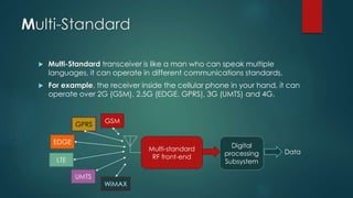
  • 2. Multi-Standard  Multi-Standard transceiver is like a man who can speak multiple languages, it can operate in different communications standards.  For example, the receiver inside the cellular phone in your hand, it can operate over 2G (GSM), 2.5G (EDGE, GPRS), 3G (UMTS) and 4G. Multi-standard RF front-end GSM EDGE GPRS LTE UMTS WiMAX Digital processing Subsystem Data
  • 3. Multi-Band  There are standards that operate on different frequency band for the same standard, for example:  WLAN IEEE 802.11 standard:  802.11a : from 5.15 to 5.35 GHz in/out Door. from 5.725 to 5.85 GHz outdoor.  802.11b/g: 2.4-2.4835-GHz.  WiMAX IEEE 802.16e:  2.5 GHz band & 3.5 GHz band.  For a Multi-Standard transceiver it should operate over different frequency bands with different bandwidths depending on each standard it supports.
  • 4. Multi-Standard transceiver:  A Multi-Band/Multi-Standard transceiver (TRX) is a radio front-end that can be operated in a number of frequency bands. The frequency bands can be changed easily without modifying the hardware.[Ref.1]  The modern upgrades of the Multi-standard transceiver are:  Software-Defined-Radio, which is a multi- standard radio with reconfigurable digital processing using embedded systems or computers.  And cognitive radio, which is a SDR with the ability of sensing the surrounding spectrum to use the unused frequency bands for better spectrum efficiency.
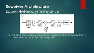
  • 6. Receiver Architecture Super-Heterodyne Receiver  The signal of interest is down-converted to an intermediate-frequency, then re- down-converted to DC (Zero IF) or very low IF.
  • 7. Receiver Architecture Super-Heterodyne Receiver Image problem.  if an interferer locates in frequency equals to fRF – 2fIF for LO < fRF or at fRF+ 2 fIF for LO> fRF, that interferer will be down-converted to the IF band of interest, interrupting the desired signal and reducing the selectivity and sensitivity of the system.
  • 8. Receiver Architecture Super-Heterodyne Receiver Image problem- low side injection. Desired Signal LO signal Interfere @ fRF-2fLO Down- converted signal Up- converted signal Interferer’s image appears at fIF
  • 9. Receiver Architecture Super-Heterodyne Receiver Advantages  Immunity to LO leakage and interferer leakage.  Negligible mismatch between I and Q channels because I&Q split is done after the second mixer where the IF is low enough. Pitfalls:  Requires more external components, not suitable for SoC.  More complicated in design.  Image problem while image rejection is not easily achievable.
  • 10. Receiver Architecture Direct conversion Receiver (Zero-IF receiver)  A simple structure where the signal is directly down-converted to zero or very low IF.  Simple LNA and channel selection filters are replaced with LPF.
  • 11. Receiver Architecture Direct conversion Receiver (Zero-IF receiver) Advantages:  Solve the problem of image.  LNA doesn’t have to drive a 50 Ohms load since there are no Image Rejection BPF.  Suitable for full integration.  Suitable for multi-standard if programmable LO frequency and LPF are used.
  • 12. Receiver Architecture Direct conversion Receiver (Zero-IF receiver) Disadvantages:  DC offset [added DC voltage to the signal causing distortion and losses].  Even order distortion.  Flicker noise.  LO leakage.  Self-mixing[adds undesired signal at zero IF].
  • 13. Receiver Architecture Quasi-IF Receiver  To solve the problems of Direct-conversion- receivers.  The signal is down-converted to a very low IF.  Image problem is re-introduced!
  • 14. Receiver Architecture Digital-IF Receivers  The signal is down-converted to intermediate frequency IF.  Then it is converted to digital using ADC.  The second down-converting and demodulation are performed in digital domain effectively.
  • 15. Receiver Architecture Digital-IF Receivers design issues:  Adjacent interferers or blockers are directly added to the ADC’s input,  so a wide dynamic range is required in the ADC to prevent ADC saturation by high power level blockers and to sense the very low level signal.  To relax the image problem, IF cannot be very low.  If the signal’s BW is comparable to the IF, Low Pass ADCs are used instead of band pass.  To relax the requirements, subsampling is used.
  • 17. Subsampling:  Subsampling is the process of sampling a signal with a frequency lower than twice the highest signal frequency, but higher than two times the signal bandwidth, the signal is down-converted by subsampling instead of mixing.
  • 18. Subsampling: selecting subsampling frequency 𝟐(𝒇 𝒄 − 𝑩𝑾 𝟐 ) 𝒎 − 𝟏 > 𝒇 𝒔 > 𝟐(𝒇 𝒄 − 𝑩𝑾 𝟐 ) 𝒎 Where:  fs : Subsampling frequency.  BW : signal bandwidth.  fc : carrier frequency.  m : number of replicas between 0Hz and (fc-BW/2). m 1, 𝑓𝑙𝑜𝑜𝑟 𝒇 𝒄 − 𝑩𝑾 𝟐 𝑩𝑾
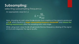
  • 19. Subsampling: selecting subsampling frequency An appropriate value for fs is 𝑓𝑠 = 4𝑓𝑐 𝑚 𝑜𝑑𝑑 Here, choosing an odd value for m ensures that a replica of the signal is produced at fs/4, which results in a larger subsampling frequency bandwidth and relaxes the filtering requirements after the sampling-and- hold stage. While using even value for m will generate the low-frequency aliasing of the signal at 3fs/4 and degrade the signal quality.
  • 20. Subsampling: Architecture Because carrier, subsampling, and intermediate frequencies are all related, there is a trade-off between bandwidth and subsampling frequency.
  • 21. Subsampling: The effect of selected subsampling frequency, which results in the presence of 2nd order effects.
  • 23. Specifications  Specific requirements:  Programmable gain.  Programmable tuning over bands of interest.  Programmable bandwidth.  Resources reuse whenever applicable.  Multi-band Frequency synthesizer. General requirements: High dynamic range. High sensitivity. High selectivity. Over all supported standards! Input Output
  • 24. Specifications  The specifications of MS radio should meet the requirements of all the supported standards in the common parts, as the UWB LNA, Mixers, …etc.  Depending on the specifications and blocking profiles, the system requirements are extracted by using the equations in the next slide.
  • 25. Specifications Equations  BW: Bandwidth.  C/N: Carrier to Noise Ratio.  PN: Phase Noise.  NF: noise figure.  SIR: Signal-to-Interferer ratio.  Safety margin is considered after calculating the system requirements.
  • 26. GSM Global System for Mobile communications. REQUIREMENTS.
  • 27. GSM GSM frequency plan  Global system for mobile communications.  Was developed by the European Telecommunications Standards Institute (ETSI) to describe the protocols for second-generation (2G) digital cellular networks used by mobile phones, first deployed in Finland in July 1991.  As of 2014 it has become the default global standard for mobile communications - with over 90% market share, operating in over 219 countries and territories. [Wikipedia] Specifications
  • 28. GSM intermodulation test  The intermodulation test specifies a Gaussian minimum shift keying (GMSK) signal 3 dB above the sensitivity level has to be detectable in presence of a 49-dBm continuous wave and a 49-dBm GMSK modulated interferer placed at 800- and 1600-kHz frequency offset from the desired signal, respectively.  Therefore, the required third-order input intercept point (IIP3) is -18 dBm. -99 dBm Desired signal @fo -49 dBm tone @fo±0.8 MHz -49dBm GMSK signal @fo±1.6 MHz
  • 29. GSM AM suppression test  GMSK is used as modulation in GSM. This modulation form has a DC peak making it vulnerable to DC offset problems.[Ref]  This test was introduced in order to avoid receiver desensitization in presence of a GMSK pulse jammer, as produced by the on/off-switching signal on another carrier.  a -99-dBm desired signal has to be correctly demodulated in presence of a -31-dBm AM modulated interferer.  IIP2> 2PAM – noise floor.  IIP2 > +49 dBm.  Challenging.
  • 30. GSM Receiver Requirements Parameter Value Sensitivity -102 dBm, with BER<10-4 Max Noise figure 9dB @200 kHz BW Antenna referred noise floor -111 dBm IIP3 -18 dBm IIP2 +49 dBm LO tuning range 60 MHz LO Phase Noise (PN) -141 dBc/Hz. Problems: • Sensitive to the 1/f noise of the CMOS in the zero-IF receiver. • Image effect in the low-IF receiver. • Very high IIP2.
  • 32. UMTS  Universal Mobile Telecommunications System.  A third generation mobile cellular system for networks based on the GSM standard.  UMTS uses wideband code division multiple access (W-CDMA) radio access technology to offer greater spectral efficiency and bandwidth to mobile network operators.  It uses WCDMA for better spectrum using efficiency.  The WCDMA coded signal modulates the carrier using QPSK.  The code used in the receiver should be well synchronized with the one used in coding the signal in transmitter.
  • 33. UMTS frequency plan  In the user equipment side:  TX : from 1920 to 1980 MHz.  RX: from 2110 to 2170 MHz.  Signal BW: 8 - 384 kHz.  Code BW: 3.84 MHz, FIXED.  Channel spacing: 5 MHz.  TX-RX spacing: 135 MHz.  Data rates:  384 kbps outdoor.  Up to 2 Mbps indoor.
  • 34. UMTS Out-of-Band Intermodulation test  The transmitter leakage is responsible for intermodulation products due to third-order nonlinearity, together with an out-of-band continuous wave interferer.  In the worst case, these two interfering signals are placed, respectively, 135 and 67.5 MHz apart from the receive band.  Since the desired signal power is 3 dB above the sensitivity level in presence of out-of-band interferers and the noise level is -99 dBm, the upper limit for the third-order intermodulation product is set at -99 dBm as well. The required out-of-band IIP3 , evaluated at the receiver input, is given by -4.6 dBm. -99dBm Desired signal @fo -40 dBm tone @fo±67.5 MHz -49dBm GMSK signal @fo±135 MHz
  • 35. UMTS In-band Intermodulation test  -46 dBm continuous wave and a -46 dBm WCDMA-modulated interfering signal, placed 10 and 20 MHz apart from the desired signal carrier frequency.  The resulting antenna referred in-band IIP3 requirement is -17 dBm.  Notice that, while the in-band requirement demands high linearity throughout the receiver (including the baseband circuits), the out-of-band specification mainly affects the RF front-end because the interferers can be strongly attenuated at the down- converter output, at least in the zero-IF or low- IF architectures. -99 dBm Desired signal @fo -46 dBm tone @fo±10 MHz -46dBm GMSK signal @fo±20 MHz
  • 36. UMTS Receiver Requirements  From the standard specifications and blocking profile the receiver requirements are calculated as following Parameter Value Sensitivity -117 Max Noise figure 6.15 dB Antenna referred noise floor -99 dBm IIP3 -4.6 dBm IIP2 +46 dBm LO tuning range 60 MHz LO Phase Noise (PN) -150 dBc/Hz. &135MHz offset.
  • 37. Bluetooth ISM BAND SHORT RANGE COMMUNICATION TECHNIQUE.
  • 38. Bluetooth  A low-cost, low-power communication protocol designed for short- range radio connectivity between electronic devices, invented by 1999.  Operates on the ISM (Industrial-Scientific-Medical) 2.4 GHz frequency band which is license-free worldwide.  Using FHSS (Frequency-Hopping-Spread-Spectrum) has the advantage of interferer immunity.  Channel BW: 1-MHz.  Modulation scheme: Binary Frequency Shift Keying (BFSK) with Gaussians shaping filter.  The Gaussian-shaped BFSK signal has most of its energy in approximately 200 kHz (3-dB bandwidth) so that a zero-IF CMOS solution would require some effort to address 1/f noise.  Low-IF receiver is selected because it allows very good sensitivity with low power consumption. Commercially, a 1 or 2 -MHz IF is chosen.
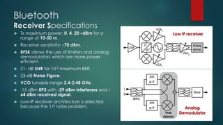
  • 39. Bluetooth Receiver Specifications Low IF receiver Analog Demodulator  Tx maximum power: 0, 4, 20 –dBm for a range of 10-50 m.  Receiver sensitivity: -70 dBm.  BFSK allows the use of limiters and analog demodulators which are more power efficient.  21- dB SNR for 10-3 maximum BER.  23-dB Noise Figure.  VCO tunable range 2.4-2.48 GHz.  -15 dBm IIP3 with -39 dBm interferers and - 64 dBm received signal.  Low-IF receiver architecture is selected because the 1/f noise problem,
  • 40. Wireless LAN HIGH-RATE WIRELESS NETWORK CONNECTIVITY.
  • 41. WLAN IEEE 802.11 Standard  Formalized in 1999, to allow high-rate wireless communication between personal computers and workstations, avoiding the use of expensive and bulky wires.  IEEE 802.11 had a maximum 2Mbps using FHSS or DSSS in the 2.4 GHz ISM band.  IEEE 802.11a has up to 54 Mbps in the 5GHz band.  IEEE 802.11b extended the throughput of IEEE 802.11 to reach 11Mbps.  IEEE 802.11g supports up to 54Mbps in the 2.4 GHz ISM band, supporting the IEEE 802.11b standard.
  • 42. WLAN IEEE 802.11a-1999  Operates on the UNII ( Universal Networking information infrastructure):  UNII-1&2 : From 5.15GHz –to- 5.35GHz: for indoor and outdoor use.  UNII-3 : From 5.725GHz –to- 5.85 GHz for outdoor use only.  Each UNII band provides four 16.6MHz OFDM modulated non- overlapping channels.  OFDM [orthogonal frequency division multiplexing] is used for its high spectral efficiency and reduced multipath inter-symbol- interference.
  • 43. IEEE 802.11a Receiver Requirements  The most stringent receiver requirements are set in the 54Mbps mode. Parameter Value Frequency band 5.15GHz –to- 5.35GHz : in/outdoor. 5.725GHz –to- 5.85 GHz : outdoor. Channel BW 16.6MHz Sensitivity -65 Max Noise figure 7.5 dB Signal-to-receiver-noise ratio 28 dB 1-dB compression point -20 dBm LO tuning range 20-40 MHz LO Phase Noise (PN) -102 dBc/Hz. &1MHz offset.
  • 44. IEEE 802.11a Receiver Requirements  OFDM modulation has a hard requirements to achieve. Receiver should has low NF less than other standards at more than twice the operating frequency.  The baseband/IF chain is also challenging because of the large bandwidth and high SNR.  For zero-IF receiver, it is required to have low 1/f noise corner frequency and HP filtering frequency to avoid signal corruption. While the training time for DC cancellation is much smaller than 802.11b, only 8μSec. Many commercial 802.11a receivers are using zero-IF architecture.  For low-IF receivers, DC offset cancellation is not a huge problem because the edges of the channel don’t carry information, and image suppression required is lower than zero-IF. The main disadvantage is the higher power consumption.
  • 45. WLAN IEEE 802.11b-1999  Operates on the ISM licence-free 2.4: 2.4835 GHz band.  Channel bandwidth: 14MHz.  Two operation modes: 5-11 Mbps  The most challenging is the 11Mbps mode, whose spectral efficiency is 0.78 bps/Hz.
  • 46. IEEE 802.11b Linearity parameters  -30 dBm continuous wave interferer or a -35 dBm adjacent signal interferer, placed 30 and 25 MHz apart from the desired signal carrier frequency.  The CW interferer sets the receiver 1-dB compression point to -26 dBm taking a 4dB safety margin.  It also sets the LO Phase noise to -103 dBc/Hz at 1-MHz offset with a VCO tuning range of 80 MHz. -70 dBm Desired signal @fo -35 dBm adjacent signal @fo±25 MHz -30dBm tone@fo±30 MHz
  • 47. IEEE 802.11b Receiver Requirements  The most stringent receiver requirements are set in the 54Mbps mode.  for IEEE 802.11b can be implemented by the zero IF receiver, where the dc offset problem is solved using HP filter and 1/f noise is integrated over the band of interest. Parameter Value Frequency band 2.4-2.4835 GHz Channel bandwidth 14 MHz Sensitivity -76 dBm Max Noise figure 14.8 dB Signal-to-noise ratio 11.5 dB 1-dB compression point -26 dBm LO tuning range 80 MHz LO Phase Noise (PN) -103 dBc/Hz. &1MHz offset.
  • 48. WLAN IEEE 802.11g-2003  IEEE 802.11g is an improvement to the IEEE 802.11 specification that extended throughput to up to 54 Mbit/s using the same 2.4 GHz band as 802.11b.  802.11g hardware is fully backwards compatible with 802.11b hardware  In an 802.11g network, the presence of a legacy 802.11b participant will significantly reduce the speed of the overall 802.11g network.  802.11g suffers from the same interference as 802.11b in the already crowded 2.4 GHz range.  802.11g receivers have to meet the most critical requirements set by 802.11b and 802.11a.  However, the 1-dB compression point is set to -10dBm in the receiver low-gain mode.
  • 49. IEEE 802.11b/g channels.  To prevent interference, there are only three non-overlapping usable channels in the U.S. and other countries with similar regulations (channels 1, 6, 11, with 25 MHz separation), and four in Europe (channels 1, 5, 9, 13, with only 20 MHz separation)  Zero-IF receiver architecture is efficiently used for IEEE 802.11g.
  • 50. IEEE 802.11n - 2009  Its purpose is to improve network throughput over the two previous standards—802.11a and 802.11g, with a significant increase in the maximum net data rate from 54 Mbit/s to 600 Mbit/s by using MIMO [Multiple-input Multiple-output].  Channel bandwidth increased from 20 MHz to 40 MHz which, besides using MIMO, increase the transfer rate of the system.  IEEE 802.11n allows up to 4×4:4 MIMO.  Data rates up to 600 Mbit/s are achieved only with the maximum of four spatial streams using one 40 MHz-wide channel.
  • 52. Multi-Standard RF front-end summary:  Multi-standard receiver can be easly implemented by making a transceiver for each standard, but this will increase both the cost and power consumption.  By carefully designed system where sharing of hardware whenever possible, and use of tunable, programmable gain & bandwidth elements are guaranteed, the power consumption and total cost can be minimized.
  • 53. THE END OF PART-1
  • 54. References:  “Toward Multistandard Mobile Terminals—Fully Integrated Receivers Requirements and Architectures”, IEEE TRANSACTIONS ON MICROWAVE THEORY AND TECHNIQUES, VOL. 53, NO. 3, MARCH 2005, Massimo Brandolini and others.  Multi-standard radio transceiver architecture and radio frequency front end design, The Ohio state university, Hyung Joon Kim, 2005.  Multi-Standard Mixed-Signal Transceivers for Wireless Communications —A Research Overview, Troels Emil Kolding, Aalborg University, Denmark, December 1996.  MULTI-STANDARD CMOS WIRELESS RECEIVERS: Analysis and Design, Consulting Editor: Mohammed Ismail. Ohio State University.

Editor's Notes

  • #19: Subsampling Receivers with Applications to Software Defined Radio Systems José R. Garcيa Oya, Andrew Kwan, Fernando Muٌoz Chavero, Fadhel M. Ghannouchi, Mohamed Helaoui, Fernando Mلrquez Lasso, Enrique Lَpez-Morillo and Antonio Torralba Silgado
  • #20: Subsampling Receivers with Applications to Software Defined Radio Systems José R. Garcيa Oya, Andrew Kwan, Fernando Muٌoz Chavero, Fadhel M. Ghannouchi, Mohamed Helaoui, Fernando Mلrquez Lasso, Enrique Lَpez-Morillo and Antonio Torralba Silgado
  • #21: Subsampling Receivers with Applications to Software Defined Radio Systems José R. Garcيa Oya, Andrew Kwan, Fernando Muٌoz Chavero, Fadhel M. Ghannouchi, Mohamed Helaoui, Fernando Mلrquez Lasso, Enrique Lَpez-Morillo and Antonio Torralba Silgado
  • #22: Subsampling Receivers with Applications to Software Defined Radio Systems José R. Garcيa Oya, Andrew Kwan, Fernando Muٌoz Chavero, Fadhel M. Ghannouchi, Mohamed Helaoui, Fernando Mلrquez Lasso, Enrique Lَpez-Morillo and Antonio Torralba Silgado